EP1296079A1 - Constant velocity joint - Google Patents
Constant velocity joint Download PDFInfo
- Publication number
- EP1296079A1 EP1296079A1 EP02078489A EP02078489A EP1296079A1 EP 1296079 A1 EP1296079 A1 EP 1296079A1 EP 02078489 A EP02078489 A EP 02078489A EP 02078489 A EP02078489 A EP 02078489A EP 1296079 A1 EP1296079 A1 EP 1296079A1
- Authority
- EP
- European Patent Office
- Prior art keywords
- cage
- inner race
- constant velocity
- ball
- velocity joint
- Prior art date
- Legal status (The legal status is an assumption and is not a legal conclusion. Google has not performed a legal analysis and makes no representation as to the accuracy of the status listed.)
- Withdrawn
Links
Images


Classifications
-
- F—MECHANICAL ENGINEERING; LIGHTING; HEATING; WEAPONS; BLASTING
- F16—ENGINEERING ELEMENTS AND UNITS; GENERAL MEASURES FOR PRODUCING AND MAINTAINING EFFECTIVE FUNCTIONING OF MACHINES OR INSTALLATIONS; THERMAL INSULATION IN GENERAL
- F16D—COUPLINGS FOR TRANSMITTING ROTATION; CLUTCHES; BRAKES
- F16D3/00—Yielding couplings, i.e. with means permitting movement between the connected parts during the drive
- F16D3/16—Universal joints in which flexibility is produced by means of pivots or sliding or rolling connecting parts
- F16D3/20—Universal joints in which flexibility is produced by means of pivots or sliding or rolling connecting parts one coupling part entering a sleeve of the other coupling part and connected thereto by sliding or rolling members
- F16D3/22—Universal joints in which flexibility is produced by means of pivots or sliding or rolling connecting parts one coupling part entering a sleeve of the other coupling part and connected thereto by sliding or rolling members the rolling members being balls, rollers, or the like, guided in grooves or sockets in both coupling parts
- F16D3/223—Universal joints in which flexibility is produced by means of pivots or sliding or rolling connecting parts one coupling part entering a sleeve of the other coupling part and connected thereto by sliding or rolling members the rolling members being balls, rollers, or the like, guided in grooves or sockets in both coupling parts the rolling members being guided in grooves in both coupling parts
- F16D3/224—Universal joints in which flexibility is produced by means of pivots or sliding or rolling connecting parts one coupling part entering a sleeve of the other coupling part and connected thereto by sliding or rolling members the rolling members being balls, rollers, or the like, guided in grooves or sockets in both coupling parts the rolling members being guided in grooves in both coupling parts the groove centre-lines in each coupling part lying on a sphere
- F16D3/2245—Universal joints in which flexibility is produced by means of pivots or sliding or rolling connecting parts one coupling part entering a sleeve of the other coupling part and connected thereto by sliding or rolling members the rolling members being balls, rollers, or the like, guided in grooves or sockets in both coupling parts the rolling members being guided in grooves in both coupling parts the groove centre-lines in each coupling part lying on a sphere where the groove centres are offset from the joint centre
-
- F—MECHANICAL ENGINEERING; LIGHTING; HEATING; WEAPONS; BLASTING
- F16—ENGINEERING ELEMENTS AND UNITS; GENERAL MEASURES FOR PRODUCING AND MAINTAINING EFFECTIVE FUNCTIONING OF MACHINES OR INSTALLATIONS; THERMAL INSULATION IN GENERAL
- F16D—COUPLINGS FOR TRANSMITTING ROTATION; CLUTCHES; BRAKES
- F16D3/00—Yielding couplings, i.e. with means permitting movement between the connected parts during the drive
- F16D3/16—Universal joints in which flexibility is produced by means of pivots or sliding or rolling connecting parts
- F16D3/20—Universal joints in which flexibility is produced by means of pivots or sliding or rolling connecting parts one coupling part entering a sleeve of the other coupling part and connected thereto by sliding or rolling members
- F16D3/22—Universal joints in which flexibility is produced by means of pivots or sliding or rolling connecting parts one coupling part entering a sleeve of the other coupling part and connected thereto by sliding or rolling members the rolling members being balls, rollers, or the like, guided in grooves or sockets in both coupling parts
- F16D3/223—Universal joints in which flexibility is produced by means of pivots or sliding or rolling connecting parts one coupling part entering a sleeve of the other coupling part and connected thereto by sliding or rolling members the rolling members being balls, rollers, or the like, guided in grooves or sockets in both coupling parts the rolling members being guided in grooves in both coupling parts
-
- F—MECHANICAL ENGINEERING; LIGHTING; HEATING; WEAPONS; BLASTING
- F16—ENGINEERING ELEMENTS AND UNITS; GENERAL MEASURES FOR PRODUCING AND MAINTAINING EFFECTIVE FUNCTIONING OF MACHINES OR INSTALLATIONS; THERMAL INSULATION IN GENERAL
- F16D—COUPLINGS FOR TRANSMITTING ROTATION; CLUTCHES; BRAKES
- F16D3/00—Yielding couplings, i.e. with means permitting movement between the connected parts during the drive
- F16D3/16—Universal joints in which flexibility is produced by means of pivots or sliding or rolling connecting parts
- F16D3/20—Universal joints in which flexibility is produced by means of pivots or sliding or rolling connecting parts one coupling part entering a sleeve of the other coupling part and connected thereto by sliding or rolling members
- F16D3/22—Universal joints in which flexibility is produced by means of pivots or sliding or rolling connecting parts one coupling part entering a sleeve of the other coupling part and connected thereto by sliding or rolling members the rolling members being balls, rollers, or the like, guided in grooves or sockets in both coupling parts
- F16D3/223—Universal joints in which flexibility is produced by means of pivots or sliding or rolling connecting parts one coupling part entering a sleeve of the other coupling part and connected thereto by sliding or rolling members the rolling members being balls, rollers, or the like, guided in grooves or sockets in both coupling parts the rolling members being guided in grooves in both coupling parts
- F16D2003/22303—Details of ball cages
-
- F—MECHANICAL ENGINEERING; LIGHTING; HEATING; WEAPONS; BLASTING
- F16—ENGINEERING ELEMENTS AND UNITS; GENERAL MEASURES FOR PRODUCING AND MAINTAINING EFFECTIVE FUNCTIONING OF MACHINES OR INSTALLATIONS; THERMAL INSULATION IN GENERAL
- F16D—COUPLINGS FOR TRANSMITTING ROTATION; CLUTCHES; BRAKES
- F16D2300/00—Special features for couplings or clutches
- F16D2300/12—Mounting or assembling
Definitions
- This invention relates to constant velocity joints.
- Constant velocity joints commonly referred to as CV joints, have long been known to eliminate the problems of sinusoidal variation of speed between the driving shaft and the driven shaft when an angle exists between the two shafts. This quality is extremely desirable in half-shafts for front wheel drive motor vehicles where a relatively high angle may exist between the drive half-shaft and the driven shaft. Because the driven shaft is connected to suspended steerable wheels, the angle may also vary.
- Rzeppa style constant velocity joints as well as other types of CV joints use balls interposed between an inner race and outer race to pass torque from one race to the other race.
- the cage has windows sized to retain the balls.
- Auctor style cages with concentric spherical inner diameters and outer diameters have been commonplace. These types of cages have an opening with a diameter that is less that the outer diameter of the inner race.
- the advantage of this type of the inner race and cage is that the inner race, once assembled within the cage, is then retained within the cage to entrap the balls and prevent them from falling out.
- the assembly of the inner race into the cage is difficult and poses some limits as to the strength of the cage.
- the installation and assembly of the inner race 20' requires that the inner race initially has its longitudinal axis orthogonal to and spaced from the longitudinal axis of the cage 30'.
- the inner race is then inserted into the cage with the rim of the cage intruding into one of the ball tracks in the inner race as illustrated in Figure 2(b).
- the inner race is then rolled further into the cage as further illustrated in figure 2(c).
- the window that receives the lobe must be lengthened to accommodate the thickness of the lobe. As such, the lengthening of the window undesirably removes structural support for the cage. This accommodation becomes even more undesirable for high angle joints.
- the thickness of the inner race and its lobes need to be increased in order to retain the ball throughout the full angular range of motion.
- the increase in thickness of the inner race and its lobes means that the window needs to be correspondingly increased in length.
- chamfering of the lobes at its ends should be minimized since chamfering removes materials from important bearing surfaces.
- the present three dimensional puzzle of fitting the inner race into the cage poses difficulty and expense for high volume automatic assembly.
- a constant velocity joint has an inner race, outer race, and a cage having windows for receiving a plurality of balls interposed between the inner race and outer race. All of the windows in the cage have equal length and are sized to be less than the thickness of each lobe of the inner race.
- the cage has an opening with a diameter that is smaller than the outer diameter of the inner race across diametrically opposed lobes but greater than or equal to the height of the inner race measured between two pair of opposed lobes.
- the constant velocity joint is a six-ball joint with the inner race having six lobes and the cage having six equally sized windows.
- the ball center radial distance from the inner opening diameter is less than approximately 3/10 the thickness of the cage wall.
- the ball center diameter for the six balls is also preferably less than 3.3 times as great as the individual ball diameter.
- the ratio of the offset from the center of plane of the balls with respect to the ball center radius is desirably greater than 0.121.
- the constant velocity joint is desirably a high angle joint with angle capabilities greater or equal to 50°.
- a constant velocity joint is a six-ball joint with the inner race having six lobes and the cage having six windows.
- the opening diameter of the cage is smaller than the outer diameter of the inner race across diametrically opposed lobes but greater than or equal to the height of the inner race measured between two pair of opposed lobes.
- a method of assembly of an inner race to a ball cage for a constant velocity joint includes the step of positioning an inner race such that its longitudinal axis is transverse to and intersecting a longitudinal axis of the ball cage.
- the lobes of the inner race are positioned such that two opposing lobes define an outer diameter of the inner race that is larger than the opening diameter of the ball cage with the outer diameter of the inner race being canted with respect to the longitudinal axis of the cage.
- the inner race height with respect to a direction transverse to the longitudinal axis of the cage between two pairs of opposing lobes is equal to or less than the opening diameter of the cage.
- the inner race is transitionally moved relative to the cage until the two pairs of lobes pass through the opening of the cage and the longitudinal axis of the inner race intersects a ball center plane of the cage.
- the inner race is then rotated with respect to the cage to align the longitudinal axis of the inner race with the longitudinal axis of the ball cage to align the diameter of the inner race parallel to the opening diameter.
- the method includes use of a six ball constant velocity joint with the inner race having six lobes and the cage having six windows for seating six balls.
- a Rzeppa style constant velocity joint 10 is shown with an outer race 12 connected to a shaft section 14 and having six ball tracks 16 on its inner face 18.
- An inner race 20 is splined to a second shaft section 22 as shown clearly in Figure 3 through a central splined opening 23 and has six ball tracks 24 on its outer face 25.
- Six lobes 26 are formed between the tracks 24.
- the ball tracks 16 and 24 hold six balls 28 which are disposed in six equally sized windows 32 of a cage 30.
- the thickness 27 of the lobes 26 may be greater that the cross-sectional length of any window 32. In other words, there is no requirement that the thickness of lobes 26 and the length of the windows need to accommodate or be dependent upon the dimension of the other.
- the outer diameter as indicated by numeral 34 in Figure 6 is greater than the diameter 36 of opening 38 in cage 30 in order to provide that the inner race 20 when fully installed within cage 30 is retained in the cage and unable to slip axially out through opening 38 or open back side 40.
- the opening 38 has no steps and has the same diameter until it contacts inner curved surface 60 of cage 30 in proximity to windows 32.
- the cage is positioned in Figure 5 relative to the inner race 30 shown in Figure 6 such that the longitudinal axis 42 is transverse and intersects the longitudinal axis 44 of the inner race 20.
- the opening 38 has its diameter 36 sized to be at least as great as the minimum projected height 46 of the inner race when the inner race 20 is rotated to have its outer diameter 34 canted with respect to the longitudinal axis 42 of cage 30.
- the minimum projected height 46 is obtained when the projection is evenly positioned between two lobes 48 of the inner race through the center 50 of the track 24.
- the inner race can then be transitionally moved into opening 38.
- the minimum projected height 46 when the two axis 42 and 44 are transverse to each other and the diameter 34 is angled as shown in Figure 6 allows the inner race to pass through the opening 38 without any needed rotation, i.e. rolling, of the inner race.
- the edge 52, i.e. rim, of opening 38 need not be received within the track 24 as previously needed with the prior art devices.
- the straight transitional movement continues until a position is achieved where the longitudinal axis 44 of the inner race intersects the ball center plane 56.
- the ball center plane 56 is transverse to the longitudinal axis 42 and contains the apexes 58 of interior surface 60 of cage 30 as well as the center of the balls as shown in Figure 1.
- the longitudinal axis 44 also intersects the spherical center 64 of the inner cage surface 60.
- the inner race is then free to rotate about a vertical axis 90° such that its longitudinal axis 44 becomes aligned with axis 42 as shown in Figure 1.
- the outer diameter 34 is rotated into the ball center plane.
- the diameter 34 prevents the inner race 20 from transitionally moving out of the cage because it is greater than the opening diameter 36 of cage 30.
- This relative size of outer diameter 34 to opening diameter 38 is further illustrated in Figure 9 where the inner race is rotated from its position shown in Figure 8 to place the diameter 34 into the ball center plane 56.
- this construction also provides that the ratio of BCD/b, i.e. the Ball Center Diameter (BCD)/ball diameter (b), is less than 3.3. This provides for larger balls more compactly spaced.
- BCD Ball Center Diameter
- b Ball diameter
- this construction provides that the ratio of the offset/BCR, i.e. 1 ⁇ 2 distance O I O O /Ball Center Radius, is greater than 0.121.
- O I is offset of the center of the inner track radius from the ball center plane 56 and
- O O is the offset of the outer track radius curvature from the ball center plane 56.
Landscapes
- Engineering & Computer Science (AREA)
- General Engineering & Computer Science (AREA)
- Mechanical Engineering (AREA)
- Rolling Contact Bearings (AREA)
Abstract
Description
- This invention relates to constant velocity joints.
- Constant velocity joints, commonly referred to as CV joints, have long been known to eliminate the problems of sinusoidal variation of speed between the driving shaft and the driven shaft when an angle exists between the two shafts. This quality is extremely desirable in half-shafts for front wheel drive motor vehicles where a relatively high angle may exist between the drive half-shaft and the driven shaft. Because the driven shaft is connected to suspended steerable wheels, the angle may also vary.
- Rzeppa style constant velocity joints as well as other types of CV joints use balls interposed between an inner race and outer race to pass torque from one race to the other race. The cage has windows sized to retain the balls.
- Auctor style cages with concentric spherical inner diameters and outer diameters have been commonplace. These types of cages have an opening with a diameter that is less that the outer diameter of the inner race. The advantage of this type of the inner race and cage is that the inner race, once assembled within the cage, is then retained within the cage to entrap the balls and prevent them from falling out. However, the assembly of the inner race into the cage is difficult and poses some limits as to the strength of the cage.
- As illustrated in Figure 2(a), the installation and assembly of the inner race 20' requires that the inner race initially has its longitudinal axis orthogonal to and spaced from the longitudinal axis of the cage 30'. The inner race is then inserted into the cage with the rim of the cage intruding into one of the ball tracks in the inner race as illustrated in Figure 2(b). The inner race is then rolled further into the cage as further illustrated in figure 2(c).
- During the rolling of the inner race into the cage, it is necessary to extend one of the lobes of the inner race into one of the windows in the cage such that the opposite side of the inner race can clear the rim of the opening of the cage to be fully inserted into the cage. Thereafter, the inner race is raised to remove the lobe from the window such that both longitudinal axes intersect as illustrated in Figure 2(d). In this position, the inner race is then free to rotate 90° as shown in Figure 2(e) to align the two longitudinal axes to complete the installation of the inner race within the cage as shown in Figure 2(f).
- The window that receives the lobe must be lengthened to accommodate the thickness of the lobe. As such, the lengthening of the window undesirably removes structural support for the cage. This accommodation becomes even more undesirable for high angle joints. In high angle joints capable of joint angles greater than or equal to 50°, the thickness of the inner race and its lobes need to be increased in order to retain the ball throughout the full angular range of motion. The increase in thickness of the inner race and its lobes means that the window needs to be correspondingly increased in length. Furthermore, chamfering of the lobes at its ends should be minimized since chamfering removes materials from important bearing surfaces.
- As one can easily determine, the present three dimensional puzzle of fitting the inner race into the cage poses difficulty and expense for high volume automatic assembly. For high angle joints, it becomes impractical to lengthen the cage window to accommodate the required thicker lobes during such an installation process and impractical to chamfer the lobes.
- In accordance with one aspect of the invention, a constant velocity joint has an inner race, outer race, and a cage having windows for receiving a plurality of balls interposed between the inner race and outer race. All of the windows in the cage have equal length and are sized to be less than the thickness of each lobe of the inner race. The cage has an opening with a diameter that is smaller than the outer diameter of the inner race across diametrically opposed lobes but greater than or equal to the height of the inner race measured between two pair of opposed lobes. In one embodiment, the constant velocity joint is a six-ball joint with the inner race having six lobes and the cage having six equally sized windows. Preferably, the ball center radial distance from the inner opening diameter is less than approximately 3/10 the thickness of the cage wall. The ball center diameter for the six balls is also preferably less than 3.3 times as great as the individual ball diameter. The ratio of the offset from the center of plane of the balls with respect to the ball center radius is desirably greater than 0.121. The constant velocity joint is desirably a high angle joint with angle capabilities greater or equal to 50°.
- In accordance with another aspect of the invention, a constant velocity joint is a six-ball joint with the inner race having six lobes and the cage having six windows. The opening diameter of the cage is smaller than the outer diameter of the inner race across diametrically opposed lobes but greater than or equal to the height of the inner race measured between two pair of opposed lobes.
- In accordance with another aspect of the invention, a method of assembly of an inner race to a ball cage for a constant velocity joint includes the step of positioning an inner race such that its longitudinal axis is transverse to and intersecting a longitudinal axis of the ball cage. In a subsequent step, the lobes of the inner race are positioned such that two opposing lobes define an outer diameter of the inner race that is larger than the opening diameter of the ball cage with the outer diameter of the inner race being canted with respect to the longitudinal axis of the cage. In this position, the inner race height with respect to a direction transverse to the longitudinal axis of the cage between two pairs of opposing lobes is equal to or less than the opening diameter of the cage.
- In a subsequent step, the inner race is transitionally moved relative to the cage until the two pairs of lobes pass through the opening of the cage and the longitudinal axis of the inner race intersects a ball center plane of the cage. The inner race is then rotated with respect to the cage to align the longitudinal axis of the inner race with the longitudinal axis of the ball cage to align the diameter of the inner race parallel to the opening diameter. Preferably, the method includes use of a six ball constant velocity joint with the inner race having six lobes and the cage having six windows for seating six balls.
- Reference now is made to the accompanying drawings in which:
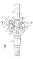
- Figure 1 is a segmented side elevational view of a constant velocity joint in accordance with one embodiment of the invention;
- Figure 2 is sequence of prior art steps showing how a conventional inner race is assembled within a conventional cage;
- Figure 3 is cross-sectional view taken along lines 3-3 as shown in Figure 1;
- Figure 4 is side elevational view of the inner race shown in Figure 1;
- Figure 5 is a side elevational view of the cage shown in Figure 1;
- Figure 6 is a plan view of the inner race shown in position to be moved into the cage shown in Figure 5;
- Figure 7 is a partially segmented view showing the inner race transitionally moved to a partially inserted position with respect to the cage;
- Figure 8 is a view similar to Figure 7 with the transitional movement of the inner race completed to fully insert the inner race with respect to the cage; and
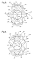
- Figure 9 is a view similar to Figure 8 illustrating how the outer diameter of the inner race when rotated into the ball center plane from the position shown in Figure 8 can retain the inner race within the cage.
-
- Referring now to Figure 1, a Rzeppa style
constant velocity joint 10 is shown with anouter race 12 connected to ashaft section 14 and having sixball tracks 16 on itsinner face 18. Aninner race 20 is splined to asecond shaft section 22 as shown clearly in Figure 3 through a centralsplined opening 23 and has sixball tracks 24 on its outer face 25. Sixlobes 26 are formed between thetracks 24. Theball tracks balls 28 which are disposed in six equally sizedwindows 32 of acage 30. - As shown in Figures 4 and 5, the
thickness 27 of thelobes 26 may be greater that the cross-sectional length of anywindow 32. In other words, there is no requirement that the thickness oflobes 26 and the length of the windows need to accommodate or be dependent upon the dimension of the other. - The outer diameter as indicated by
numeral 34 in Figure 6 is greater than thediameter 36 of opening 38 incage 30 in order to provide that theinner race 20 when fully installed withincage 30 is retained in the cage and unable to slip axially out through opening 38 or openback side 40. Theopening 38 has no steps and has the same diameter until it contacts innercurved surface 60 ofcage 30 in proximity towindows 32. - The cage is positioned in Figure 5 relative to the
inner race 30 shown in Figure 6 such that thelongitudinal axis 42 is transverse and intersects thelongitudinal axis 44 of theinner race 20. Theopening 38 has itsdiameter 36 sized to be at least as great as the minimum projectedheight 46 of the inner race when theinner race 20 is rotated to have itsouter diameter 34 canted with respect to thelongitudinal axis 42 ofcage 30. The minimum projectedheight 46 is obtained when the projection is evenly positioned between two lobes 48 of the inner race through thecenter 50 of thetrack 24. The inner race can then be transitionally moved intoopening 38. As shown in Figure 7, the minimum projectedheight 46 when the twoaxis diameter 34 is angled as shown in Figure 6 allows the inner race to pass through theopening 38 without any needed rotation, i.e. rolling, of the inner race. As shown in Figure 7, theedge 52, i.e. rim, of opening 38 need not be received within thetrack 24 as previously needed with the prior art devices. - As shown in Figure 8, the straight transitional movement continues until a position is achieved where the
longitudinal axis 44 of the inner race intersects theball center plane 56. Theball center plane 56 is transverse to thelongitudinal axis 42 and contains theapexes 58 ofinterior surface 60 ofcage 30 as well as the center of the balls as shown in Figure 1. For Auctor type cages where theinner surface 60 defines a spherical undercut, thelongitudinal axis 44 also intersects thespherical center 64 of theinner cage surface 60. - From the position shown in Figure 8, the inner race is then free to rotate about a vertical axis 90° such that its
longitudinal axis 44 becomes aligned withaxis 42 as shown in Figure 1. In this position theouter diameter 34 is rotated into the ball center plane. When in this position, thediameter 34 prevents theinner race 20 from transitionally moving out of the cage because it is greater than theopening diameter 36 ofcage 30. This relative size ofouter diameter 34 to openingdiameter 38 is further illustrated in Figure 9 where the inner race is rotated from its position shown in Figure 8 to place thediameter 34 into theball center plane 56. - This construction provides that the ratio C/D where C is the distance on the
inner rim 52 of opening 38 to the ball center position and D is thickness of the cage, is less than 0.3 as shown in Figure 1. - Referring now to Figure 3, this construction also provides that the ratio of BCD/b, i.e. the Ball Center Diameter (BCD)/ball diameter (b), is less than 3.3. This provides for larger balls more compactly spaced.
- Furthermore, this construction provides that the ratio of the offset/BCR, i.e. ½ distance OIOO/Ball Center Radius, is greater than 0.121. OI is offset of the center of the inner track radius from the
ball center plane 56 and OO is the offset of the outer track radius curvature from theball center plane 56. Again, this enlarged ratio over the prior art denotes the compactness of the ball centers relative to the other structures to provide a high angle joint with increased durability. This construction provides for an increase in joint angle of 4° to a joint angle capacity of 50° over the conventional constructions. - Variations and modifications are possible without departing from the scope and spirit of the present invention as defined by the appended claims.
Claims (6)
- A six ball constant velocity joint comprising:wherein said cage (30) has an opening (38) at one end thereof having an inner diameter dimension (36) relatively less than the first outer diameter dimension (34) of said inner race (20), but equal to or relatively greater than the second outer diameter dimension (46) of said inner race (20).an inner race (20) having six circumferentially spaced lobes (26) defining ball-accommodating tracks (24) between said lobes (26), said inner race (20) having a first outer diameter dimension (34) measured between opposing ones of said lobes (26) and a second relatively smaller, outer diameter dimension (46) measured between opposing projection lines of opposing ones of said tracks (24) extending across said tracks (24) between the outermost extent of the lobes (26) adjacent each of said tracks (24);an outer race (12) disposed about said inner race (20);a cage (30) disposed between said inner race (20) and said outer race (12) and having six circumferentially spaced windows (32);a set of six torque-transmitting balls (28) disposed between said inner race (20) and said outer race (12) and accommodated in said windows (32) of said cage (30); and
- The six ball constant velocity joint of claim 1 wherein said windows (32) of said cage (30) have uniform equal length in the circumferential direction of said cage (30) and said lobes (26) have equal axial thickness greater than the length of said windows (32).
- A constant velocity joint (10) as defined in claim 3 further comprising:the ball center radial distance (C) from the inner opening is less than approximately 3/10 the thickness (D) of the cage wall.
- A constant velocity joint (10) as defined in claim 2 further comprising:the ball center diameter (BCD) for the six balls being less than 3.3. times as great as the individual ball diameter (b).
- A constant velocity joint (10) as defined in claim 4 further comprising:said ratio of the offset of the constant velocity joint with respect to the ball center radius being greater than 0.121.
- A constant velocity joint (10) as defined in claim 2 further comprising:said joint having a high angle capability to be greater or equal to 50°.
Applications Claiming Priority (2)
| Application Number | Priority Date | Filing Date | Title |
|---|---|---|---|
| US09/960,092 US20030054893A1 (en) | 2001-09-20 | 2001-09-20 | Constant velocity joint |
| US960092 | 2001-09-20 |
Publications (1)
| Publication Number | Publication Date |
|---|---|
| EP1296079A1 true EP1296079A1 (en) | 2003-03-26 |
Family
ID=25502786
Family Applications (1)
| Application Number | Title | Priority Date | Filing Date |
|---|---|---|---|
| EP02078489A Withdrawn EP1296079A1 (en) | 2001-09-20 | 2002-08-23 | Constant velocity joint |
Country Status (3)
| Country | Link |
|---|---|
| US (1) | US20030054893A1 (en) |
| EP (1) | EP1296079A1 (en) |
| JP (1) | JP2003113856A (en) |
Cited By (3)
| Publication number | Priority date | Publication date | Assignee | Title |
|---|---|---|---|---|
| WO2006136308A1 (en) * | 2005-06-21 | 2006-12-28 | Volkswagen Aktiengesellschaft | Constant-velocity fixed joint |
| EP2149719A4 (en) * | 2007-03-27 | 2012-01-04 | Ntn Toyo Bearing Co Ltd | Fixed uniform-motion universal coupling |
| WO2026147297A1 (en) * | 2025-01-03 | 2026-07-09 | 현대위아 주식회사 | Constant velocity joint |
Families Citing this family (6)
| Publication number | Priority date | Publication date | Assignee | Title |
|---|---|---|---|---|
| JP2007503556A (en) * | 2003-08-22 | 2007-02-22 | ゲー カー エヌ ドライブライン ドイチュラント ゲゼルシャフト ミット ベシュレンクテル ハフツング | Fixed ball joint with twisted track cross section |
| JP4223358B2 (en) * | 2003-09-04 | 2009-02-12 | Ntn株式会社 | Fixed constant velocity universal joint |
| DE602004030359D1 (en) * | 2003-10-01 | 2011-01-13 | Ntn Toyo Bearing Co Ltd | HOMOKINETIC UNIVERSAL FEAST |
| EP1707835B1 (en) * | 2004-01-15 | 2010-12-22 | Honda Motor Co., Ltd. | Constant velocity joint |
| KR100879631B1 (en) | 2006-07-27 | 2009-01-21 | 한국델파이주식회사 | Constant velocity joint for automobile |
| KR101542396B1 (en) * | 2008-11-21 | 2015-08-07 | 삼성디스플레이 주식회사 | Thin film transistor display panel and manufacturing method thereof |
Citations (3)
| Publication number | Priority date | Publication date | Assignee | Title |
|---|---|---|---|---|
| US5167584A (en) * | 1991-02-21 | 1992-12-01 | Gkn Automotive, Inc. | Constant velocity universal joint and a method for making same |
| JPH09177810A (en) * | 1995-12-28 | 1997-07-11 | Ntn Corp | Cage for constant velocity universal joint and assembling method thereof |
| EP0802341A1 (en) * | 1995-12-26 | 1997-10-22 | Ntn Corporation | Constant velocity universal coupling |
-
2001
- 2001-09-20 US US09/960,092 patent/US20030054893A1/en not_active Abandoned
-
2002
- 2002-08-23 EP EP02078489A patent/EP1296079A1/en not_active Withdrawn
- 2002-09-20 JP JP2002274400A patent/JP2003113856A/en active Pending
Patent Citations (3)
| Publication number | Priority date | Publication date | Assignee | Title |
|---|---|---|---|---|
| US5167584A (en) * | 1991-02-21 | 1992-12-01 | Gkn Automotive, Inc. | Constant velocity universal joint and a method for making same |
| EP0802341A1 (en) * | 1995-12-26 | 1997-10-22 | Ntn Corporation | Constant velocity universal coupling |
| JPH09177810A (en) * | 1995-12-28 | 1997-07-11 | Ntn Corp | Cage for constant velocity universal joint and assembling method thereof |
Non-Patent Citations (1)
| Title |
|---|
| PATENT ABSTRACTS OF JAPAN vol. 1997, no. 11 28 November 1997 (1997-11-28) * |
Cited By (7)
| Publication number | Priority date | Publication date | Assignee | Title |
|---|---|---|---|---|
| WO2006136308A1 (en) * | 2005-06-21 | 2006-12-28 | Volkswagen Aktiengesellschaft | Constant-velocity fixed joint |
| US7544132B2 (en) | 2005-06-21 | 2009-06-09 | Volkswagen Aktiengesellschaft | Constant-velocity fixed joint |
| CN101203687B (en) * | 2005-06-21 | 2010-06-09 | 大众汽车有限公司 | Synchronous articulated joint |
| EP2149719A4 (en) * | 2007-03-27 | 2012-01-04 | Ntn Toyo Bearing Co Ltd | Fixed uniform-motion universal coupling |
| US8282495B2 (en) | 2007-03-27 | 2012-10-09 | Ntn Corporation | Fixed type constant velocity universal joint |
| EP2530345A1 (en) * | 2007-03-27 | 2012-12-05 | NTN Corporation | Fixed uniform-motion universal coupling |
| WO2026147297A1 (en) * | 2025-01-03 | 2026-07-09 | 현대위아 주식회사 | Constant velocity joint |
Also Published As
| Publication number | Publication date |
|---|---|
| US20030054893A1 (en) | 2003-03-20 |
| JP2003113856A (en) | 2003-04-18 |
Similar Documents
| Publication | Publication Date | Title |
|---|---|---|
| EP0844412B1 (en) | Sliding type constant-speed universal joint | |
| US6234908B1 (en) | Drive assembly with at least one constant velocity fixed joint having a set of rolling contact member guiding means | |
| US7407441B2 (en) | Constant velocity joint | |
| JP2002181066A (en) | Constant velocity ball joint as opposed track joint | |
| EP0950824A2 (en) | Constant velocity joint and rolling bearing unit for wheel | |
| US5167584A (en) | Constant velocity universal joint and a method for making same | |
| EP0463531A1 (en) | Constant velocity joint having cross grooves | |
| US20030054893A1 (en) | Constant velocity joint | |
| US6270419B1 (en) | Constant velocity fixed joint with two sets of running grooves extending in opposite directions | |
| EP1707835B1 (en) | Constant velocity joint | |
| US7806772B2 (en) | Homokinetic displacement joint | |
| US6241615B1 (en) | Constant velocity fixed joint with an axially mountable cage | |
| US7544132B2 (en) | Constant-velocity fixed joint | |
| US6398657B2 (en) | Constant velocity fixed joint | |
| US20030232654A1 (en) | Tripot universal joint | |
| JP2003508697A (en) | Constant speed universal ball joint | |
| CN1049050A (en) | Constant Velocity Universal Joint | |
| CN101493119A (en) | Constant velocity joint | |
| US6176787B1 (en) | Tripod constant velocity joint | |
| JP2002532663A (en) | Ball cam centering mechanism | |
| CN119137386A (en) | Reverse track hinge | |
| JPH06500159A (en) | constant velocity universal joint | |
| US7878914B2 (en) | Constant velocity joint of tripod type | |
| JP3767168B2 (en) | Constant velocity joints and rolling bearing units for wheels with constant velocity joints | |
| JP2003329053A (en) | Drive shaft |
Legal Events
| Date | Code | Title | Description |
|---|---|---|---|
| PUAI | Public reference made under article 153(3) epc to a published international application that has entered the european phase |
Free format text: ORIGINAL CODE: 0009012 |
|
| AK | Designated contracting states |
Kind code of ref document: A1 Designated state(s): AT BE BG CH CY CZ DE DK EE ES FI FR GB GR IE IT LI LU MC NL PT SE SK TR Designated state(s): AT BE BG CH CY CZ DE DK EE ES FI FR GB GR IE IT LI LU MC NL PT SE SK TR |
|
| AX | Request for extension of the european patent |
Extension state: AL LT LV MK RO SI |
|
| AKX | Designation fees paid | ||
| REG | Reference to a national code |
Ref country code: DE Ref legal event code: 8566 |
|
| STAA | Information on the status of an ep patent application or granted ep patent |
Free format text: STATUS: THE APPLICATION IS DEEMED TO BE WITHDRAWN |
|
| 18D | Application deemed to be withdrawn |
Effective date: 20030927 |