EP1296073A1 - Method and apparatus for balancing driveshafts - Google Patents
Method and apparatus for balancing driveshafts Download PDFInfo
- Publication number
- EP1296073A1 EP1296073A1 EP02020610A EP02020610A EP1296073A1 EP 1296073 A1 EP1296073 A1 EP 1296073A1 EP 02020610 A EP02020610 A EP 02020610A EP 02020610 A EP02020610 A EP 02020610A EP 1296073 A1 EP1296073 A1 EP 1296073A1
- Authority
- EP
- European Patent Office
- Prior art keywords
- driveshaft
- yoke
- balancing
- tubular element
- flange
- Prior art date
- Legal status (The legal status is an assumption and is not a legal conclusion. Google has not performed a legal analysis and makes no representation as to the accuracy of the status listed.)
- Granted
Links
Images
Classifications
-
- F—MECHANICAL ENGINEERING; LIGHTING; HEATING; WEAPONS; BLASTING
- F16—ENGINEERING ELEMENTS AND UNITS; GENERAL MEASURES FOR PRODUCING AND MAINTAINING EFFECTIVE FUNCTIONING OF MACHINES OR INSTALLATIONS; THERMAL INSULATION IN GENERAL
- F16F—SPRINGS; SHOCK-ABSORBERS; MEANS FOR DAMPING VIBRATION
- F16F15/00—Suppression of vibrations in systems; Means or arrangements for avoiding or reducing out-of-balance forces, e.g. due to motion
- F16F15/32—Correcting- or balancing-weights or equivalent means for balancing rotating bodies, e.g. vehicle wheels
- F16F15/322—Correcting- or balancing-weights or equivalent means for balancing rotating bodies, e.g. vehicle wheels the rotating body being a shaft
-
- F—MECHANICAL ENGINEERING; LIGHTING; HEATING; WEAPONS; BLASTING
- F16—ENGINEERING ELEMENTS AND UNITS; GENERAL MEASURES FOR PRODUCING AND MAINTAINING EFFECTIVE FUNCTIONING OF MACHINES OR INSTALLATIONS; THERMAL INSULATION IN GENERAL
- F16C—SHAFTS; FLEXIBLE SHAFTS; ELEMENTS OR CRANKSHAFT MECHANISMS; ROTARY BODIES OTHER THAN GEARING ELEMENTS; BEARINGS
- F16C3/00—Shafts; Axles; Cranks; Eccentrics
- F16C3/02—Shafts; Axles
-
- F—MECHANICAL ENGINEERING; LIGHTING; HEATING; WEAPONS; BLASTING
- F16—ENGINEERING ELEMENTS AND UNITS; GENERAL MEASURES FOR PRODUCING AND MAINTAINING EFFECTIVE FUNCTIONING OF MACHINES OR INSTALLATIONS; THERMAL INSULATION IN GENERAL
- F16C—SHAFTS; FLEXIBLE SHAFTS; ELEMENTS OR CRANKSHAFT MECHANISMS; ROTARY BODIES OTHER THAN GEARING ELEMENTS; BEARINGS
- F16C2326/00—Articles relating to transporting
- F16C2326/01—Parts of vehicles in general
- F16C2326/06—Drive shafts
Definitions
- the present invention relates to driveshafts and, more particularly, to a method and an apparatus for balancing the rotational imbalance of a driveshaft.
- a driveshaft for the driveline is formed by a roll formed tube which includes yokes welded at each end.
- the yokes receive universal joints to be connected with other components.
- the tube although manufactured to tight tolerances, will not be uniformly cylindrical, in cross-section, or absolutely straight throughout its length.
- the tube will have irregularity in its wall thickness.
- irregularities appear in the cast or forged yokes which are connected to the tube.
- the material in geometrical variations will provide an incongruent mass and rotational centers causing eccentric loading imbalance. This may lead to vibration and vehicle noise which will be amplified by the constant whipping of the unbalanced weight distribution of the driveline.
- the present invention overcomes the drawbacks of the prior art.
- the present invention provides an assembly where, instead of adding material, material is removed to balance the driveshaft.
- the yokes include a portion which enables removal of material or mass to balance the rotational imbalance.
- Figure 1 is a schematic view of a driveline of a vehicle including a driveshaft in accordance with the present invention.
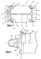
- Figure 2 is a plan view of a driveline assembly in accordance with the present invention.
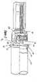
- Figure 3 is an enlarged partial section view of an end of the driveshaft of Figure 2.
- the driveline 10 is that of a four-wheel vehicle 12.
- the vehicle includes an engine 14 with a gear box 16 and a front axle differential 18.
- the front wheels 20 are driven via front driveshafts 22.
- the driving torque for the rear wheels 24 is branched off from the front axle differential 18 and transmitted to the rear axle differential 26 via a divided longitudinal driveshaft 28 and 30.
- the rear axle differential 26 drives the rear wheels.
- the front and rear driveshafts, as well as the divided longitudinal driveshaft, may be designed in accordance with the invention.
- the driveshaft includes a tubular portion 42 which has two ends. Each end includes a yoke 44 which is welded to the tube 42. Also, the yokes 44 include ears 46 which receive the universal joint 48. The universal joint 48 is coupled with a second yoke 50.
- the tube 42 may be steel or aluminum.
- the tube 42 has a desired diameter as well as tube thickness. While the tube is manufactured within tight tolerances, discontinuities exist along the circumferential cross-section as well as along the longitudinal axis of the tube. The variations of the thickness of the tube is what causes rotational imbalances.
- the yoke 44 includes a body 52.
- the ears 46 project from the body 52.
- the ears include cross-holes 54 which receive the bearing assembly of the universal joint 48.
- a skirt portion 56 projects from the other side of the body 52. The skirt portion 56 is inserted inside of the tube 42. The tube is then welded via weld 58 to the yoke 44.
- the yoke body 52 includes a flange portion 60.
- the flange circumferentially surrounds the body 52.
- the flange 60 radially projects beyond the diameter of the tube 42.
- the flange 60 includes at least one bore 62.
- the bore 62 could be replaced by a ground portion or the bore could be a notched or cut portion.
- the removal of material from the flange 60 which forms the bore 62 is provided to balance the rotation of the driveshaft. By removing material from the flange 60, a rotational balance may be achieved in the driveshaft.
- the present invention eliminates the need for adding material to the driveshaft or yoke.
- the disadvantages which are present in adding material to the driveshaft are removed.
- the driveshaft of the present invention is balanced as follows.
- a tubular member is provided.
- Yoke members are coupled or welded to the ends of the tubular element.
- the yoke members include flanges like those described.
- the driveshaft is rotated at a desired speed.
- vibrational imbalance can be determined.
- a position is indicated as to where and how much material is to be removed.
- the material is removed from the flange by cutting, boring or grinding the material from the flange. After this occurs, the driveshaft is rotated again to determine that rotational balance has been achieved. If a rotational imbalance would exist, the above process would be repeated.
- a driveshaft 22, 28, 30, or 32 comprises a tubular element 42 having two ends, at least one yoke 44 being coupled with one end of said tubular element 42.
- Said at least one yoke 44 includes a stub shaft portion 56 for coupling with said tubular element 42, and a receiving portion 46 for receiving a joint 48.
- a balancing portion 60 for balancing shaft rotation said balancing portion 60 including a desired mass of material, wherein said balancing portion 60 enables mass reduction so that mass may be removed from said balancing portion 60 so that rotational imbalance of said driveshaft 22, 28, 30, or 32, during rotation, is eliminated.
- Said balancing portion 60 is positioned between said stub shaft portion 56 and said receiving portion 46 and is a circumferential flange 60 that may be bored, ground, cut, or the like to remove material from said flange 60.
- a method of balancing a driveshaft 22, 28, 30, or 32 comprises the steps of:
Landscapes
- Engineering & Computer Science (AREA)
- General Engineering & Computer Science (AREA)
- Mechanical Engineering (AREA)
- Ocean & Marine Engineering (AREA)
- Physics & Mathematics (AREA)
- Acoustics & Sound (AREA)
- Aviation & Aerospace Engineering (AREA)
- Motor Power Transmission Devices (AREA)
- Shafts, Cranks, Connecting Bars, And Related Bearings (AREA)
Abstract
Description
- The present invention relates to driveshafts and, more particularly, to a method and an apparatus for balancing the rotational imbalance of a driveshaft.
- Balancing of automotive drivelines is critical to provide optimum performance of the automotive vehicle. Ordinarily, a driveshaft for the driveline is formed by a roll formed tube which includes yokes welded at each end. The yokes receive universal joints to be connected with other components. The tube, although manufactured to tight tolerances, will not be uniformly cylindrical, in cross-section, or absolutely straight throughout its length. The tube will have irregularity in its wall thickness. Similarly, irregularities appear in the cast or forged yokes which are connected to the tube. The material in geometrical variations will provide an incongruent mass and rotational centers causing eccentric loading imbalance. This may lead to vibration and vehicle noise which will be amplified by the constant whipping of the unbalanced weight distribution of the driveline.
- In order to balance the steel driveshafts and yoke, ordinarily a small weight is welded to the steel tubes or preferably to the end of the tubes adjacent the overlap of the yokes. Also, adhesive metallic tape had been utilized in an attempt to balance driveshafts. Further, riveted pads, which pierce the wall of the drive tubes, have been used. Disadvantages of the above is that the adhesive bond may become contaminated and fail. Also, the piercing of the tube creates an unsealed tube which violates automotive requirements. Thus, welding balancing weights onto the tube is the predominant technique.
- With the advent of aluminum or aluminum base driveshafts, the welding of material cannot be used since the steel weights do not weld or braise to the aluminum material. Less dense weights, such as aluminum weights, which would weld to the aluminum, are used. However, the size and mass of proper distribution of weight made their use difficult. Thus, using the dissimilar metals on an aluminum driveshaft assembly remains a difficult process.
- The present invention overcomes the drawbacks of the prior art. The present invention provides an assembly where, instead of adding material, material is removed to balance the driveshaft. The yokes include a portion which enables removal of material or mass to balance the rotational imbalance.
- From the following detailed description, taken in conjunction with the drawings and subjoined claims, other objects and advantages of the present invention will become apparent to those skilled in the art.
- Figure 1 is a schematic view of a driveline of a vehicle including a driveshaft in accordance with the present invention.
- Figure 2 is a plan view of a driveline assembly in accordance with the present invention.
- Figure 3 is an enlarged partial section view of an end of the driveshaft of Figure 2.
- Turning to the figures, particularly Figure 1, a driveline is illustrated and designated with the
reference numeral 10. Thedriveline 10 is that of a four-wheel vehicle 12. The vehicle includes anengine 14 with agear box 16 and afront axle differential 18. Thefront wheels 20 are driven viafront driveshafts 22. The driving torque for therear wheels 24 is branched off from thefront axle differential 18 and transmitted to therear axle differential 26 via a dividedlongitudinal driveshaft 28 and 30. Via therear driveshafts 32, therear axle differential 26 drives the rear wheels. The front and rear driveshafts, as well as the divided longitudinal driveshaft, may be designed in accordance with the invention. - Turning to Figure 2, a driveshaft is illustrated. The driveshaft includes a
tubular portion 42 which has two ends. Each end includes ayoke 44 which is welded to thetube 42. Also, theyokes 44 includeears 46 which receive theuniversal joint 48. Theuniversal joint 48 is coupled with asecond yoke 50. - The
tube 42 may be steel or aluminum. Thetube 42 has a desired diameter as well as tube thickness. While the tube is manufactured within tight tolerances, discontinuities exist along the circumferential cross-section as well as along the longitudinal axis of the tube. The variations of the thickness of the tube is what causes rotational imbalances. - The
yoke 44 includes abody 52. Theears 46 project from thebody 52. The ears includecross-holes 54 which receive the bearing assembly of theuniversal joint 48. Askirt portion 56 projects from the other side of thebody 52. Theskirt portion 56 is inserted inside of thetube 42. The tube is then welded viaweld 58 to theyoke 44. - The
yoke body 52 includes aflange portion 60. The flange circumferentially surrounds thebody 52. Theflange 60 radially projects beyond the diameter of thetube 42. Theflange 60, as shown, includes at least onebore 62. Thebore 62 could be replaced by a ground portion or the bore could be a notched or cut portion. The removal of material from theflange 60 which forms thebore 62 is provided to balance the rotation of the driveshaft. By removing material from theflange 60, a rotational balance may be achieved in the driveshaft. Thus, the present invention eliminates the need for adding material to the driveshaft or yoke. Thus, the disadvantages which are present in adding material to the driveshaft are removed. - The driveshaft of the present invention is balanced as follows. A tubular member is provided. Yoke members are coupled or welded to the ends of the tubular element. The yoke members include flanges like those described. The driveshaft is rotated at a desired speed. As the driveshaft is rotated, vibrational imbalance can be determined. After the vibrational imbalance is determined, a position is indicated as to where and how much material is to be removed. The material is removed from the flange by cutting, boring or grinding the material from the flange. After this occurs, the driveshaft is rotated again to determine that rotational balance has been achieved. If a rotational imbalance would exist, the above process would be repeated.
- While the above detailed description describes the preferred embodiment of the present invention, the invention is susceptible to modification, variation and alteration without deviating from the scope and fair meaning of the subjoined claims.
- To summarize, a
driveshaft tubular element 42 having two ends, at least oneyoke 44 being coupled with one end of saidtubular element 42. Said at least oneyoke 44 includes astub shaft portion 56 for coupling with saidtubular element 42, and a receivingportion 46 for receiving a joint 48. - Further provided is a balancing
portion 60 for balancing shaft rotation, said balancingportion 60 including a desired mass of material, wherein said balancingportion 60 enables mass reduction so that mass may be removed from said balancingportion 60 so that rotational imbalance of saiddriveshaft - Said balancing
portion 60 is positioned between saidstub shaft portion 56 and said receivingportion 46 and is acircumferential flange 60 that may be bored, ground, cut, or the like to remove material from saidflange 60. - A method of balancing a
driveshaft - providing a
driveshaft tubular element 42 with two ends and ayoke 44 coupled at each end of saidtubular element 42, - removing material from at least one of said yokes 44, and
- balancing rotational imbalance of said
driveshaft yoke 44. -
Claims (9)
- A driveshaft comprising a tubular element (42) having two ends, at least one yoke (44) coupled with one end of said tubular element (42), said at least one yoke (44) including a stub shaft portion (56) for coupling with said tubular element (42), and a receiving portion (46) for receiving a joint (48),
Characterized by a balancing portion (60) for balancing shaft rotation, said balancing portion (60) including a desired mass of material, wherein said balancing portion (60) enables mass reduction so that mass may be removed from said balancing portion (60) so that rotational imbalance of said driveshaft (22, 28, 30, 32), during rotation, being eliminated. - The driveshaft of claim 1, characterized in that a yoke (44) is at each end of said driveshaft (22, 28, 30, 32).
- The driveshaft of claim 1 or claim 2, characterized in that said balancing portion (60) is positioned between said stub shaft portion (56) and said receiving portion (46).
- The driveshaft of anyone of claims 1 - 3, characterized in that said balancing portion (60) is a circumferential flange (60).
- The driveshaft of claim 4, characterized in that said circumferential flange (60) may be bored, ground, cut, or the like to remove material from said flange (60).
- A method of balancing a driveshaft (22, 28, 30, 32), comprising the steps of:providing a driveshaft (22, 28, 30, 32) having a tubular element (42) with two ends and a yoke (44) coupled at each end of said tubular element (42),removing material from at least one of said yokes (44), andbalancing rotational imbalance of said driveshaft (22, 28, 30, 32) through said removal of material from said at least one yoke (44).
- The method of claim 6, characterized by providing a flange (60) on said at least one yoke (44).
- The method of claim 7, characterized by removing material from said flange (60).
- The method of claim 7 or claim 8, characterized by boring, grinding, cutting or the like, said flange (60) for removing said material.
Applications Claiming Priority (2)
| Application Number | Priority Date | Filing Date | Title |
|---|---|---|---|
| US09/951,205 US20030050127A1 (en) | 2001-09-13 | 2001-09-13 | Method and apparatus for balancing driveshafts |
| US951205 | 2001-09-13 |
Publications (2)
| Publication Number | Publication Date |
|---|---|
| EP1296073A1 true EP1296073A1 (en) | 2003-03-26 |
| EP1296073B1 EP1296073B1 (en) | 2006-11-02 |
Family
ID=25491415
Family Applications (1)
| Application Number | Title | Priority Date | Filing Date |
|---|---|---|---|
| EP02020610A Expired - Lifetime EP1296073B1 (en) | 2001-09-13 | 2002-09-13 | Method and apparatus for balancing driveshafts |
Country Status (4)
| Country | Link |
|---|---|
| US (1) | US20030050127A1 (en) |
| EP (1) | EP1296073B1 (en) |
| DE (1) | DE60215741T2 (en) |
| ES (1) | ES2275791T3 (en) |
Families Citing this family (5)
| Publication number | Priority date | Publication date | Assignee | Title |
|---|---|---|---|---|
| US6813973B1 (en) * | 2003-08-20 | 2004-11-09 | Torque-Traction Technologies, Inc. | Drive shaft balancing |
| FR2903467B1 (en) * | 2006-07-10 | 2009-04-24 | Gkn Driveline Sa Sa | SOLDER TUBE SHAFT FITTING, SHAFT AND METHOD FOR MANUFACTURING THE SAME. |
| JP5946637B2 (en) * | 2011-12-16 | 2016-07-06 | Udトラックス株式会社 | Propeller shaft dropout prevention structure |
| US9696233B2 (en) * | 2014-08-18 | 2017-07-04 | American Axle & Manufacturing, Inc. | Method for balancing a propshaft assembly |
| US11994179B2 (en) | 2018-03-23 | 2024-05-28 | Dana Automotive Systems Group, Llc | Correcting an imbalance in a rotating shaft |
Citations (3)
| Publication number | Priority date | Publication date | Assignee | Title |
|---|---|---|---|---|
| EP0056306A2 (en) * | 1981-01-10 | 1982-07-21 | Brd Company Limited | Balancing of shafts |
| US5165305A (en) * | 1990-12-11 | 1992-11-24 | Westinghouse Electric Corp. | Hermetically sealed flywheel and method of making the same |
| US5214585A (en) * | 1989-06-30 | 1993-05-25 | General Electric Company | Balancing method and product |
Family Cites Families (14)
| Publication number | Priority date | Publication date | Assignee | Title |
|---|---|---|---|---|
| US2950082A (en) * | 1955-04-18 | 1960-08-23 | John R Mcveigh | Turbine wheel assembly |
| DE1573495A1 (en) * | 1965-10-26 | 1970-08-13 | Bodenseewerk Geraetetech | Method and device for balancing, in particular gyroscopes |
| US3472998A (en) * | 1967-04-03 | 1969-10-14 | Nasa | Laser apparatus for removing material from rotating objects |
| US3795784A (en) * | 1971-08-06 | 1974-03-05 | Singer Co | Balancing system for a rotating mass |
| US4380443A (en) * | 1979-11-17 | 1983-04-19 | Felten & Guilleaume Carlswerk Aktiengesellschaft | Fiber-reinforced drive shaft |
| IT1146185B (en) * | 1980-08-08 | 1986-11-12 | Cnen | PROCEDURE AND EQUIPMENT FOR THE DYNAMIC BALANCING OF BODYWHEELS |
| DE3208780A1 (en) * | 1982-03-11 | 1983-09-22 | J.M. Voith Gmbh, 7920 Heidenheim | PTO SHAFT WITH DIRECTIONAL DEVICE |
| US4472158A (en) * | 1982-05-26 | 1984-09-18 | Dana Corporation | Heavy duty yoke |
| US5234378A (en) * | 1990-08-06 | 1993-08-10 | Ford Motor Company | Balanced rotary assembly |
| US5716276A (en) * | 1996-09-03 | 1998-02-10 | Dana Corporation | Yoke shaft for a vehicular driveshaft assembly |
| US5868626A (en) * | 1997-04-30 | 1999-02-09 | Dana Corporation | Universal joint yoke having axially-extending grooves |
| US6303896B1 (en) * | 1999-08-02 | 2001-10-16 | Visteon Global Technologies, Inc. | Dynamic laser balancing |
| US6655208B1 (en) * | 1999-08-31 | 2003-12-02 | Torque-Traction Technologies, Inc. | Method and apparatus for balancing a vehicular driveshaft |
| US6694812B2 (en) * | 2001-04-12 | 2004-02-24 | Schenck Rotec Corporation | Rotatable shaft balancing machine and method with automatic flexible shaft balancing equipment |
-
2001
- 2001-09-13 US US09/951,205 patent/US20030050127A1/en not_active Abandoned
-
2002
- 2002-09-13 DE DE60215741T patent/DE60215741T2/en not_active Expired - Lifetime
- 2002-09-13 ES ES02020610T patent/ES2275791T3/en not_active Expired - Lifetime
- 2002-09-13 EP EP02020610A patent/EP1296073B1/en not_active Expired - Lifetime
Patent Citations (3)
| Publication number | Priority date | Publication date | Assignee | Title |
|---|---|---|---|---|
| EP0056306A2 (en) * | 1981-01-10 | 1982-07-21 | Brd Company Limited | Balancing of shafts |
| US5214585A (en) * | 1989-06-30 | 1993-05-25 | General Electric Company | Balancing method and product |
| US5165305A (en) * | 1990-12-11 | 1992-11-24 | Westinghouse Electric Corp. | Hermetically sealed flywheel and method of making the same |
Also Published As
| Publication number | Publication date |
|---|---|
| US20030050127A1 (en) | 2003-03-13 |
| EP1296073B1 (en) | 2006-11-02 |
| DE60215741D1 (en) | 2006-12-14 |
| DE60215741T2 (en) | 2007-09-06 |
| ES2275791T3 (en) | 2007-06-16 |
Similar Documents
| Publication | Publication Date | Title |
|---|---|---|
| US6874228B2 (en) | Propshaft assembly with vibration attenuation and assembly method therefor | |
| US6923058B2 (en) | System and method for balancing a driveline system | |
| CA2047460A1 (en) | Rotationally balanced assembly | |
| US7178423B2 (en) | Noise and vibration damper for a vehicular driveshaft assembly | |
| US6855061B2 (en) | Vehicular driveshaft assembly | |
| US6773354B2 (en) | Driveshaft assembly that is balanced for rotation and method of manufacturing same | |
| US6367680B1 (en) | Component for vehicular driveshaft assembly and method of manufacturing same | |
| KR100694341B1 (en) | Aluminum Propulsion Shaft with Constant Speed Joint | |
| EP1296073B1 (en) | Method and apparatus for balancing driveshafts | |
| EP1605178A2 (en) | Flange assembly for supporting a bearing and an end fitting in a driveshaft assembly | |
| AU2003200876A1 (en) | Yoke Structure That is Adapted To be Secured To a Tube Using Magnetic Pulse Welding Techniques | |
| EP1493511A1 (en) | Method of manufacturing a combined driveshaft tube and yoke assembly | |
| AU2005202744A1 (en) | Method of manufacturing a combined driveshaft tube and yoke assembly | |
| US6792660B1 (en) | Method for manufacturing a driveshaft assembly that is balanced for rotation | |
| US5692959A (en) | Tube yoke with diamond-shaped relief | |
| US6655208B1 (en) | Method and apparatus for balancing a vehicular driveshaft | |
| US20030203758A1 (en) | Integrated driveline flange torsional damper | |
| EP0056306B1 (en) | Balancing of shafts | |
| US20060219005A1 (en) | Method for balancing an article for rotation | |
| US20050109446A1 (en) | Method for balancing a vehicle driveshaft | |
| US5868626A (en) | Universal joint yoke having axially-extending grooves | |
| GB2382118A (en) | Method of balancing an article for rotation | |
| US20210025456A1 (en) | Correcting an imbalance in a rotating shaft | |
| US7004840B1 (en) | Internal balance correction device for vehicular driveshaft assembly | |
| JP2519725Y2 (en) | Propeller shaft for vehicle |
Legal Events
| Date | Code | Title | Description |
|---|---|---|---|
| PUAI | Public reference made under article 153(3) epc to a published international application that has entered the european phase |
Free format text: ORIGINAL CODE: 0009012 |
|
| AK | Designated contracting states |
Kind code of ref document: A1 Designated state(s): AT BE BG CH CY CZ DE DK EE ES FI FR GB GR IE IT LI LU MC NL PT SE SK TR |
|
| AX | Request for extension of the european patent |
Extension state: AL LT LV MK RO SI |
|
| RIN1 | Information on inventor provided before grant (corrected) |
Inventor name: MENOSKY, MARC M. Inventor name: SIVAKUMAR, KARTHIK Inventor name: BARRETT, MARK S. |
|
| 17P | Request for examination filed |
Effective date: 20030522 |
|
| AKX | Designation fees paid |
Designated state(s): DE ES FR GB IT |
|
| 17Q | First examination report despatched |
Effective date: 20050415 |
|
| GRAP | Despatch of communication of intention to grant a patent |
Free format text: ORIGINAL CODE: EPIDOSNIGR1 |
|
| GRAS | Grant fee paid |
Free format text: ORIGINAL CODE: EPIDOSNIGR3 |
|
| GRAA | (expected) grant |
Free format text: ORIGINAL CODE: 0009210 |
|
| AK | Designated contracting states |
Kind code of ref document: B1 Designated state(s): DE ES FR GB IT |
|
| REG | Reference to a national code |
Ref country code: GB Ref legal event code: FG4D |
|
| REF | Corresponds to: |
Ref document number: 60215741 Country of ref document: DE Date of ref document: 20061214 Kind code of ref document: P |
|
| ET | Fr: translation filed | ||
| REG | Reference to a national code |
Ref country code: ES Ref legal event code: FG2A Ref document number: 2275791 Country of ref document: ES Kind code of ref document: T3 |
|
| PLBE | No opposition filed within time limit |
Free format text: ORIGINAL CODE: 0009261 |
|
| STAA | Information on the status of an ep patent application or granted ep patent |
Free format text: STATUS: NO OPPOSITION FILED WITHIN TIME LIMIT |
|
| 26N | No opposition filed |
Effective date: 20070803 |
|
| PGFP | Annual fee paid to national office [announced via postgrant information from national office to epo] |
Ref country code: ES Payment date: 20071024 Year of fee payment: 6 Ref country code: IT Payment date: 20070927 Year of fee payment: 6 |
|
| PGFP | Annual fee paid to national office [announced via postgrant information from national office to epo] |
Ref country code: FR Payment date: 20070914 Year of fee payment: 6 |
|
| REG | Reference to a national code |
Ref country code: FR Ref legal event code: ST Effective date: 20090529 |
|
| PG25 | Lapsed in a contracting state [announced via postgrant information from national office to epo] |
Ref country code: IT Free format text: LAPSE BECAUSE OF NON-PAYMENT OF DUE FEES Effective date: 20080913 |
|
| PG25 | Lapsed in a contracting state [announced via postgrant information from national office to epo] |
Ref country code: FR Free format text: LAPSE BECAUSE OF NON-PAYMENT OF DUE FEES Effective date: 20080930 |
|
| REG | Reference to a national code |
Ref country code: ES Ref legal event code: FD2A Effective date: 20080915 |
|
| PGFP | Annual fee paid to national office [announced via postgrant information from national office to epo] |
Ref country code: GB Payment date: 20090929 Year of fee payment: 8 |
|
| PG25 | Lapsed in a contracting state [announced via postgrant information from national office to epo] |
Ref country code: ES Free format text: LAPSE BECAUSE OF NON-PAYMENT OF DUE FEES Effective date: 20080915 |
|
| GBPC | Gb: european patent ceased through non-payment of renewal fee |
Effective date: 20100913 |
|
| PG25 | Lapsed in a contracting state [announced via postgrant information from national office to epo] |
Ref country code: GB Free format text: LAPSE BECAUSE OF NON-PAYMENT OF DUE FEES Effective date: 20100913 |
|
| PGFP | Annual fee paid to national office [announced via postgrant information from national office to epo] |
Ref country code: DE Payment date: 20190918 Year of fee payment: 18 |
|
| REG | Reference to a national code |
Ref country code: DE Ref legal event code: R119 Ref document number: 60215741 Country of ref document: DE |
|
| PG25 | Lapsed in a contracting state [announced via postgrant information from national office to epo] |
Ref country code: DE Free format text: LAPSE BECAUSE OF NON-PAYMENT OF DUE FEES Effective date: 20210401 |