EP1296044A2 - Idling speed control apparatus for internal combustion engine - Google Patents
Idling speed control apparatus for internal combustion engine Download PDFInfo
- Publication number
- EP1296044A2 EP1296044A2 EP02016893A EP02016893A EP1296044A2 EP 1296044 A2 EP1296044 A2 EP 1296044A2 EP 02016893 A EP02016893 A EP 02016893A EP 02016893 A EP02016893 A EP 02016893A EP 1296044 A2 EP1296044 A2 EP 1296044A2
- Authority
- EP
- European Patent Office
- Prior art keywords
- idling
- step number
- engine
- present position
- control apparatus
- Prior art date
- Legal status (The legal status is an assumption and is not a legal conclusion. Google has not performed a legal analysis and makes no representation as to the accuracy of the status listed.)
- Granted
Links
Images




Classifications
-
- F—MECHANICAL ENGINEERING; LIGHTING; HEATING; WEAPONS; BLASTING
- F02—COMBUSTION ENGINES; HOT-GAS OR COMBUSTION-PRODUCT ENGINE PLANTS
- F02D—CONTROLLING COMBUSTION ENGINES
- F02D41/00—Electrical control of supply of combustible mixture or its constituents
- F02D41/24—Electrical control of supply of combustible mixture or its constituents characterised by the use of digital means
- F02D41/2406—Electrical control of supply of combustible mixture or its constituents characterised by the use of digital means using essentially read only memories
- F02D41/2425—Particular ways of programming the data
- F02D41/2429—Methods of calibrating or learning
- F02D41/2451—Methods of calibrating or learning characterised by what is learned or calibrated
-
- F—MECHANICAL ENGINEERING; LIGHTING; HEATING; WEAPONS; BLASTING
- F02—COMBUSTION ENGINES; HOT-GAS OR COMBUSTION-PRODUCT ENGINE PLANTS
- F02D—CONTROLLING COMBUSTION ENGINES
- F02D31/00—Use of speed-sensing governors to control combustion engines, not otherwise provided for
- F02D31/001—Electric control of rotation speed
- F02D31/002—Electric control of rotation speed controlling air supply
- F02D31/003—Electric control of rotation speed controlling air supply for idle speed control
- F02D31/005—Electric control of rotation speed controlling air supply for idle speed control by controlling a throttle by-pass
-
- F—MECHANICAL ENGINEERING; LIGHTING; HEATING; WEAPONS; BLASTING
- F02—COMBUSTION ENGINES; HOT-GAS OR COMBUSTION-PRODUCT ENGINE PLANTS
- F02D—CONTROLLING COMBUSTION ENGINES
- F02D41/00—Electrical control of supply of combustible mixture or its constituents
- F02D41/02—Circuit arrangements for generating control signals
- F02D41/04—Introducing corrections for particular operating conditions
- F02D41/06—Introducing corrections for particular operating conditions for engine starting or warming up
- F02D41/062—Introducing corrections for particular operating conditions for engine starting or warming up for starting
-
- F—MECHANICAL ENGINEERING; LIGHTING; HEATING; WEAPONS; BLASTING
- F02—COMBUSTION ENGINES; HOT-GAS OR COMBUSTION-PRODUCT ENGINE PLANTS
- F02D—CONTROLLING COMBUSTION ENGINES
- F02D41/00—Electrical control of supply of combustible mixture or its constituents
- F02D41/02—Circuit arrangements for generating control signals
- F02D41/18—Circuit arrangements for generating control signals by measuring intake air flow
-
- F—MECHANICAL ENGINEERING; LIGHTING; HEATING; WEAPONS; BLASTING
- F02—COMBUSTION ENGINES; HOT-GAS OR COMBUSTION-PRODUCT ENGINE PLANTS
- F02D—CONTROLLING COMBUSTION ENGINES
- F02D11/00—Arrangements for, or adaptations to, non-automatic engine control initiation means, e.g. operator initiated
- F02D11/06—Arrangements for, or adaptations to, non-automatic engine control initiation means, e.g. operator initiated characterised by non-mechanical control linkages, e.g. fluid control linkages or by control linkages with power drive or assistance
- F02D11/10—Arrangements for, or adaptations to, non-automatic engine control initiation means, e.g. operator initiated characterised by non-mechanical control linkages, e.g. fluid control linkages or by control linkages with power drive or assistance of the electric type
- F02D2011/101—Arrangements for, or adaptations to, non-automatic engine control initiation means, e.g. operator initiated characterised by non-mechanical control linkages, e.g. fluid control linkages or by control linkages with power drive or assistance of the electric type characterised by the means for actuating the throttles
- F02D2011/104—Arrangements for, or adaptations to, non-automatic engine control initiation means, e.g. operator initiated characterised by non-mechanical control linkages, e.g. fluid control linkages or by control linkages with power drive or assistance of the electric type characterised by the means for actuating the throttles using electric step motors
-
- F—MECHANICAL ENGINEERING; LIGHTING; HEATING; WEAPONS; BLASTING
- F02—COMBUSTION ENGINES; HOT-GAS OR COMBUSTION-PRODUCT ENGINE PLANTS
- F02D—CONTROLLING COMBUSTION ENGINES
- F02D41/00—Electrical control of supply of combustible mixture or its constituents
- F02D41/24—Electrical control of supply of combustible mixture or its constituents characterised by the use of digital means
- F02D41/2406—Electrical control of supply of combustible mixture or its constituents characterised by the use of digital means using essentially read only memories
- F02D41/2425—Particular ways of programming the data
- F02D41/2429—Methods of calibrating or learning
- F02D41/2441—Methods of calibrating or learning characterised by the learning conditions
-
- F—MECHANICAL ENGINEERING; LIGHTING; HEATING; WEAPONS; BLASTING
- F02—COMBUSTION ENGINES; HOT-GAS OR COMBUSTION-PRODUCT ENGINE PLANTS
- F02D—CONTROLLING COMBUSTION ENGINES
- F02D41/00—Electrical control of supply of combustible mixture or its constituents
- F02D41/24—Electrical control of supply of combustible mixture or its constituents characterised by the use of digital means
- F02D41/2406—Electrical control of supply of combustible mixture or its constituents characterised by the use of digital means using essentially read only memories
- F02D41/2425—Particular ways of programming the data
- F02D41/2429—Methods of calibrating or learning
- F02D41/2451—Methods of calibrating or learning characterised by what is learned or calibrated
- F02D41/2464—Characteristics of actuators
Definitions
- This invention relates to an idling speed control apparatus for an internal combustion engine, and more particularly to an idling speed control apparatus for an internal combustion engine which regulates the intake air amount by means of a step motor to control the speed of rotation of the internal combustion engine upon idling.
- an idling speed control valve (ISCV) is in most cases provided midway of a bypass path provided separately from an intake path in such a manner as to bypass a throttle valve.
- the intake air amount of the internal combustion engine is controlled, independently of the throttle valve, to control the idling speed.
- the ISCV described above is driven by a step motor, and the opening thereof is controlled by supplying to the step motor a pulse signal which corresponds to the difference between the present position of an idling regulation valve which is determined by the operation step number of the step motor from a reference position and a target position which depends upon the operation condition of the engine.
- a control method as just described is known, for example, by the official gazette of Japanese Patent Laid-open No. Sho 63-42106 and so forth.
- a fixed pulse signal is provided to the step motor to drive the idling regulation valve to its fully closed or fully open position immediately after the ignition switch is disconnected, and the operation step number of the step motor is reset in order to use the fully closed or fully open position as a reference position.
- the object of the present invention resides in solution of the subject of the prior art described above and provision of an idling speed control apparatus for an internal combustion engine which can perform positioning of a step motor accurately without additionally providing a battery.
- an idling speed control apparatus for an internal combustion engine which includes an idling regulating valve for regulating the opening of an idling intake path and a step motor for driving the idling regulating valve to perform opening and closing movements and which controls the rotational position of the step motor to coincide with a rotational position corresponding to a target opening for the idling regulating valve
- storage means for storing an idling reference step number
- idling state discrimination means for discriminating whether or not the idling is in a steady state, means for rewriting the present position step number into a reference step number which is a predetermined constant when it is discriminated that the id
- the opening of the idling regulation vale when idling is stable and in a steady state is determined uniquely, and even if the engine is stopped, the idling regulation valve is kept at the position.
- the rotational position of the step motor when idling is in a steady state is stored as the idling reference step number, and when the engine is started next, the rotational position of the step motor at the point of time is set to the idling reference step number stored in advance. Consequently, the relationship between the rotational position of the step motor and the operation step number which represents the present position of the step motor can be determined accurately without using a sensor.
- FIG. 1 is a schematic sectional view showing a configuration of a principal portion of an idling speed control apparatus to which the present invention is applied.
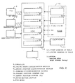
- FIG. 2 is a functional block diagram showing a configuration of a controller of FIG. 1.
- FIG. 3 is a flow chart illustrating operation of the present embodiment.
- FIG. 4 is a flow chart illustrating operation of the present embodiment.
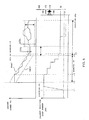
- FIG. 5 is a time chart illustrating operation of the present embodiment.
- FIG. 6 is a diagram illustrating an example of a first warming-up table.
- FIG. 7 is a diagram illustrating an example of a second warming-up table.
- FIG. 1 is a schematic sectional view showing a configuration of a principal portion of an idling speed control apparatus to which the present invention is applied.
- a throttle body 2 is mounted at an intermediate portion of an intake path which interconnects an air cleaner and an engine.
- a throttle valve 3 which regulates the opening of the intake path is provided for pivotal motion, and also an idling intake path 4 which bypasses the throttle valve 3 is mounted.
- the idling intake path 4 introduces intake air for idling to the engine upon idling of the engine and an idling regulation valve 6 is mounted between the upstream side 4a and the down stream side 4b of the idling intake path 4.
- the opening of the idling regulation valve 6 depends upon the rotational position of a step motor 1 which is driven with a pulse signal outputted from a controller 5.
- the controller 5 receives detection signals from a temperature sensor 7 which detects a cooling water temperature of the engine, an engine speed sensor 8 which detects an engine speed Ne, and a position sensor 9 which detects a gear position of a transmission, and controls the rotational position of the step motor 1.
- an engine stop step number Pstop which represents the rotational position of the step motor 1 upon last stopping of the engine is stored in a non-volatile EEPROM 11 which does not require backup power.
- the controller 5 Upon next starting of the engine, the controller 5 reads in the engine stop step number Pstop from the EEPROM 11, and supposes that the step number Pstop represents the rotational position of the step motor 1 at present (upon last engine stopping, that is, upon present engine starting) to start control.
- FIG. 2 is a functional block diagram showing a configuration of the controller 5, and like elements to those appearing as above are denoted by like or equivalent reference characters.
- an engine starting discrimination section 51 discriminates whether or not the engine is started.
- An idling state discrimination section 52 discriminates whether or not the idling is stabilized and settled in a steady state.
- a warming-up discrimination section 53 discriminates whether or not the engine is in a warming-up operation state.
- a present position counter 54 counts a present position step number Px which represents the rotational position of the step motor 1 at present.
- a target position step number Pt relating to the step motor 1 is registered into a target position counter 55.
- a motor driving section 56 supplies a driving pulse for forward rotation or reverse rotation to the step motor 1 so as to make the present position step number Px and the target position step number Pt coincide with each other.
- the driving pulse is counted by the present position counter 54 and the present position step number Px is incremented or decremented in accordance with the driving pulse.
- FIGS. 3 and 4 are flow charts illustrating operation of the present embodiment and FIG. 5 is a time chart illustrating operation of the present embodiment.
- step S1 the engine starting discrimination section 51 of the controller 5 discriminates whether or not the engine is in a starting state based on the engine speed Ne detected, for example, by the Ne sensor 8. In the present embodiment, when the engine speed Ne is 700 rpm or less, it is discriminated that the engine is in a starting state. In the beginning of the process, since it is discriminated that the engine is in a starting state, the process advances to step S11.
- step S11 the engine stop step number Pstop which represents the rotational position of the step motor 1 upon last stopping of the engine is read out from the EEPROM 11 by the controller 5.
- the read out engine stop step number Pstop is registered as the present position step number Px which represents the rotational position of the step motor 1 into the present position counter 54 of the controller 5.
- a warming-up step number Padd for temporarily raising the idling speed upon warming-up operation is detected based on the present cooling water temperature Te detected by the temperature sensor 7 with reference to a first warming-up table 101 of a ROM 10.
- FIG. 6 is a graph showing an example of the first warming-up table in the present embodiment.
- the warming-up step number Padd increases as the cooling water temperature Te decreases.
- an idling reference step number Pidle (50 steps in the present embodiment) fixedly determined in advance as a reference step number upon idling is read out from the ROM 10.
- step S15 a sum value [Pidle + (Padd - Pstop)] of the idling reference step number Pidle and a value obtained by subtracting the engine stop step number Pstop from the warming-up step number Padd is registered as a present target position step number Pt into the target position counter 55 of the controller 5.
- step S16 the present position step number Px is stored as the engine stop step number Pstop into the EEPROM 11.
- step S17 the step motor 1 is controlled by the motor driving section 56 of the controller 5 so that the target position step number Pt and the present position step number Px coincide with each other. Then, the engine is started at time t2 of FIG. 5, and when the starting of the engine is detected in step S1 described above, the process advances to step S2.
- step S2 whether or not the engine is in a no-load state is discriminated based on, for example, the gear position detected by the gear position sensor 9. If the gear position is the neutral position, then it is discriminated that the engine is in a no-load state, and the process advances to step S3.
- step S3 whether or not the engine is in an idling state is discriminated based on, for example, the engine speed Ne and the throttle opening. If the engine speed Ne is lower than a predetermined reference speed and the throttle opening is lower than a predetermined reference opening, then it is discriminated that the engine is in an idling state, and the process advances to step S4. It is to be noted that, if any one of the discriminations in steps S2 and S3 results in the negative, then the process advances to a running mode of step S10.
- step S4 it is discriminated by the warming-up discrimination section 53 of the controller 5 based on, for example, the water temperature Te of cooling water whether or not the engine is in a warming-up state.
- the water temperature Te is low and it is discriminated that the engine is in a warming-up state, and the process advances to step S5.
- step S5 an upper limit value Nmax1 and a lower limit value Nmin1 of a target idling speed range are determined based on a second warming-up table, of which an example is shown in FIG. 7, and the water temperature Te.
- step S6 and S7 it is discriminated whether or not the engine speed Ne is higher than the upper limit value Nmax1 and whether or not the engine speed Ne is lower than the lower limit value Nmin1, respectively. If the engine speed Ne reaches the upper limit value Nmax1 as at time t3 of FIG. 5, the target position step number Pt is decremented at step S8. On the contrary if the engine speed Ne drops to the lower limit value Nmin1, then the target position step number Pt is incremented at step S9. If the engine speed Ne is within the range between the upper and lower limit values, then the process advances immediately to step S16 et seq.
- an idling stability flag Fidle is referred to.
- the idling stability flag Fidle is set, as hereinafter described in detail, when idling is stabilized and it is discriminated that the idling is in a steady state. Since, in the beginning of the process, the idling is in a transition state and the idling stability flag Fidle is in a reset state, the process advances to step S22.
- the target rotational range for the engine speed Ne is set to a rather narrow value ⁇ Nn.
- step S23 it is discriminated whether or not the engine speed Ne has converged to a value within the target rotational range ⁇ Nn. Since, in the beginning of the process, it is discriminated that the engine speed Ne has not converged, the process advances to step S28. At step S28, the idling stability flag Fidle is reset. At step S29, it is discriminated whether or not the engine speed Ne is higher than the upper limit value to the target rotational range ⁇ Nn. If the engine speed Ne reaches the upper limit value as at time t5 of FIG. 5, then the target position step number Pt is decremented at step S30, whereafter the process advances to step S16 et seq. On the contrary, if the engine speed Ne is lower than the upper limit value, then the target position step number Pt is incremented at step S31, whereafter the process advances to step S16 et seq.
- the present position step number Px is stored as the engine stop step number Pstop into the EEPROM 11 in a similar manner as described hereinabove, and motor control for making the present position step number Px coincide with the target position step number Pt is performed.
- step S24 the idling stability flag Fidle is referred to again, and if the idling stability flag Fidle is in a reset state, then the process advances to step S25.
- the idling stability flag Fidle is set.
- the present position step number Px is stored as the engine stop step number Pstop into the EEPROM 11 in a similar manner as described hereinabove, and motor control for making the present position step number Px coincide with the target position step number Pt is performed.
- the rotational position of the step motor when idling is in a steady state is set to a predetermined reference step number (Pidle) based on the empirical rule that the absolute rotational position of a step motor when idling is stable and in a steady state is substantially fixed. Therefore, the relationship between the present position of the step motor and the present position step number which represents the present position can be compensated for accurately without using a sensor.
- a predetermined reference step number Pidle
- the idling speed control apparatus includes storage means 11 for storing an engine stop step number Pstop, means for driving the step motor based on a target position step number Pt which represents a target position of the step motor and a present position step number Px which represents the present position of the step motor, and idling state discrimination means 52 for discriminating whether or not the idling is in a steady state.
- the engine stop step number Pstop is registered as the present position step number, and when it is discriminated that the idling is in a steady state, the present position step number is rewritten into a reference step number which is a predetermined constant and the present position step number is stored as the idling reference step number.
Landscapes
- Engineering & Computer Science (AREA)
- Chemical & Material Sciences (AREA)
- Combustion & Propulsion (AREA)
- Mechanical Engineering (AREA)
- General Engineering & Computer Science (AREA)
- Electrical Control Of Air Or Fuel Supplied To Internal-Combustion Engine (AREA)
- Combined Controls Of Internal Combustion Engines (AREA)
- Control Of Vehicle Engines Or Engines For Specific Uses (AREA)
Abstract
Description
Then, the engine is started at time t2 of FIG. 5, and when the starting of the engine is detected in step S1 described above, the process advances to step S2. At step S2, whether or not the engine is in a no-load state is discriminated based on, for example, the gear position detected by the
The idling speed control apparatus includes storage means 11 for storing an engine stop step number Pstop, means for driving the step motor based on a target position step number Pt which represents a target position of the step motor and a present position step number Px which represents the present position of the step motor, and idling state discrimination means 52 for discriminating whether or not the idling is in a steady state. Upon starting of the engine, the engine stop step number Pstop is registered as the present position step number, and when it is discriminated that the idling is in a steady state, the present position step number is rewritten into a reference step number which is a predetermined constant and the present position step number is stored as the idling reference step number.
Claims (4)
- An idling speed control apparatus for an internal combustion engine which includes an idling regulating valve (6) for regulating the opening of an idling intake path (4) and a step motor (1) for driving said idling regulating valve (6) to perform opening and closing movements and which controls the rotational position of said step motor (1) to coincide with a rotational position corresponding to a target opening for said idling regulating valve (6), characterized in that it comprises:storage means (10) for storing an idling reference step number (Pidle) ;idling state discrimination means (52) for discriminating whether or not the idling is in a steady state;means (5) for rewriting a present position step number (Px) which represents the present position of said step motor into the reference step number (Pidle) when it is discriminated that the idling is in a steady state; andmeans (5) for driving said step motor based on a target position step number (Pt) which represents a target position of said step motor (1) and the present position step number (Px).
- An idling speed control apparatus for an internal combustion engine according to claim 1, characterized in that it further comprises
storage means (11) for repetitively storing the present position step number (Px) as an engine stop step number (Pstop) in a non-volatile fashion, and
means (5) for adopting the engine stop step number (Pstop) as the present position step number (Px) upon engine starting. - An idling speed control apparatus for an internal combustion engine according to claim 2, characterized in that said means (11) for storing the engine stop step number (Pstop) is a non-volatile memory.
- An idling speed control apparatus for an internal combustion engine according to claim 1 or 2, characterized in that it comprises
means (7) for detecting an engine temperature (Te) upon engine starting, and
means for correcting the target position step number based on the detected engine temperature.
Applications Claiming Priority (2)
| Application Number | Priority Date | Filing Date | Title |
|---|---|---|---|
| JP2001291297A JP2003097320A (en) | 2001-09-25 | 2001-09-25 | Idle speed control device for internal combustion engine |
| JP2001291297 | 2001-09-25 |
Publications (3)
| Publication Number | Publication Date |
|---|---|
| EP1296044A2 true EP1296044A2 (en) | 2003-03-26 |
| EP1296044A3 EP1296044A3 (en) | 2006-05-03 |
| EP1296044B1 EP1296044B1 (en) | 2011-03-23 |
Family
ID=19113469
Family Applications (1)
| Application Number | Title | Priority Date | Filing Date |
|---|---|---|---|
| EP20020016893 Expired - Lifetime EP1296044B1 (en) | 2001-09-25 | 2002-07-30 | Idling speed control apparatus for internal combustion engine |
Country Status (3)
| Country | Link |
|---|---|
| EP (1) | EP1296044B1 (en) |
| JP (1) | JP2003097320A (en) |
| DE (1) | DE60239511D1 (en) |
Cited By (1)
| Publication number | Priority date | Publication date | Assignee | Title |
|---|---|---|---|---|
| CN103195597A (en) * | 2013-04-07 | 2013-07-10 | 奇瑞汽车股份有限公司 | Method and device for controlling self-learning of stepping motor |
Families Citing this family (1)
| Publication number | Priority date | Publication date | Assignee | Title |
|---|---|---|---|---|
| JP2022183610A (en) * | 2021-05-31 | 2022-12-13 | 愛三工業株式会社 | engine throttle controller |
Family Cites Families (4)
| Publication number | Priority date | Publication date | Assignee | Title |
|---|---|---|---|---|
| JPH063161B2 (en) * | 1986-09-10 | 1994-01-12 | トヨタ自動車株式会社 | Idle speed control device |
| JP2847142B2 (en) * | 1989-05-18 | 1999-01-13 | 富士重工業株式会社 | Engine idle speed control device |
| US5228421A (en) * | 1992-10-28 | 1993-07-20 | Ford Motor Company | Idle speed control system |
| JP2922752B2 (en) * | 1993-07-29 | 1999-07-26 | 三菱電機株式会社 | Step motor drive controller |
-
2001
- 2001-09-25 JP JP2001291297A patent/JP2003097320A/en active Pending
-
2002
- 2002-07-30 EP EP20020016893 patent/EP1296044B1/en not_active Expired - Lifetime
- 2002-07-30 DE DE60239511T patent/DE60239511D1/en not_active Expired - Lifetime
Cited By (2)
| Publication number | Priority date | Publication date | Assignee | Title |
|---|---|---|---|---|
| CN103195597A (en) * | 2013-04-07 | 2013-07-10 | 奇瑞汽车股份有限公司 | Method and device for controlling self-learning of stepping motor |
| CN103195597B (en) * | 2013-04-07 | 2016-01-06 | 奇瑞汽车股份有限公司 | The method and apparatus of control step motor self study |
Also Published As
| Publication number | Publication date |
|---|---|
| DE60239511D1 (en) | 2011-05-05 |
| EP1296044A3 (en) | 2006-05-03 |
| JP2003097320A (en) | 2003-04-03 |
| EP1296044B1 (en) | 2011-03-23 |
Similar Documents
| Publication | Publication Date | Title |
|---|---|---|
| KR101364836B1 (en) | Control apparatus for number of revolutions of engine and control method for number of revolutions of engine | |
| EP0206272B1 (en) | Apparatus for controlling idling rotation number of internal combustion engines | |
| JPH0681931B2 (en) | Fuel pump controller | |
| JPS61145340A (en) | Method of feedback-controlling number of idle revolutions of internal combustion engine | |
| US6948477B2 (en) | Idle speed control device | |
| EP1296044B1 (en) | Idling speed control apparatus for internal combustion engine | |
| US5852998A (en) | Fuel-injection control device for outboard motors | |
| EP0807751B1 (en) | Idling control apparatus of internal combustion engine | |
| JPH07133740A (en) | Idle control valve diagnostic device | |
| JPH09264179A (en) | Intake air flow controller for internal combustion engine | |
| EP0787897B1 (en) | Suction air control apparatus of internal combustion engine | |
| US5191865A (en) | Engine idle control system for vehicle | |
| US6817339B2 (en) | Engine control device | |
| KR19990050653A (en) | Children's idle speed control device and method | |
| JP3092442B2 (en) | Intake air amount control device for internal combustion engine | |
| JP2533554B2 (en) | Automatic transmission control device | |
| JPS623144A (en) | Engine throttle opening controller | |
| JPH02191840A (en) | Internal combustion engine idle speed control device | |
| JP2560437B2 (en) | Idle rotation speed control device | |
| JP2646406B2 (en) | Idle detection device for internal combustion engine | |
| CA2043205C (en) | Engine start control system | |
| JPH10299550A (en) | Idle speed control device for internal combustion engine | |
| JP2004100469A (en) | Throttle valve control device for internal combustion engine | |
| JPH04136444A (en) | Idle speed controller | |
| JPH06100129B2 (en) | Idle speed control device for internal combustion engine |
Legal Events
| Date | Code | Title | Description |
|---|---|---|---|
| PUAI | Public reference made under article 153(3) epc to a published international application that has entered the european phase |
Free format text: ORIGINAL CODE: 0009012 |
|
| AK | Designated contracting states |
Kind code of ref document: A2 Designated state(s): AT BE BG CH CY CZ DE DK EE ES FI FR GB GR IE IT LI LU MC NL PT SE SK TR |
|
| AX | Request for extension of the european patent |
Extension state: AL LT LV MK RO SI |
|
| PUAL | Search report despatched |
Free format text: ORIGINAL CODE: 0009013 |
|
| AK | Designated contracting states |
Kind code of ref document: A3 Designated state(s): AT BE BG CH CY CZ DE DK EE ES FI FR GB GR IE IT LI LU MC NL PT SE SK TR |
|
| AX | Request for extension of the european patent |
Extension state: AL LT LV MK RO SI |
|
| 17P | Request for examination filed |
Effective date: 20060622 |
|
| 17Q | First examination report despatched |
Effective date: 20060919 |
|
| AKX | Designation fees paid |
Designated state(s): DE FR GB IT |
|
| GRAP | Despatch of communication of intention to grant a patent |
Free format text: ORIGINAL CODE: EPIDOSNIGR1 |
|
| GRAS | Grant fee paid |
Free format text: ORIGINAL CODE: EPIDOSNIGR3 |
|
| GRAA | (expected) grant |
Free format text: ORIGINAL CODE: 0009210 |
|
| RIN1 | Information on inventor provided before grant (corrected) |
Inventor name: ANDO, HIDEAKI,C/O KABUSHIKI KAISHA HONDA GIJUTSU K Inventor name: URAKI, MAMORU,C/O KABUSHIKI KAISHA HONDA GIJUTSU K Inventor name: HIRAKATA, YOSHIAKI, C/O KABUSHIKI KAISHA HONDA GIJ Inventor name: ITO, NOBUHIKO,C/O KABUSHIKI KAISHA HONDA GIJUTSU K |
|
| AK | Designated contracting states |
Kind code of ref document: B1 Designated state(s): DE FR GB IT |
|
| REG | Reference to a national code |
Ref country code: GB Ref legal event code: FG4D |
|
| REF | Corresponds to: |
Ref document number: 60239511 Country of ref document: DE Date of ref document: 20110505 Kind code of ref document: P |
|
| REG | Reference to a national code |
Ref country code: DE Ref legal event code: R096 Ref document number: 60239511 Country of ref document: DE Effective date: 20110505 |
|
| PLBE | No opposition filed within time limit |
Free format text: ORIGINAL CODE: 0009261 |
|
| STAA | Information on the status of an ep patent application or granted ep patent |
Free format text: STATUS: NO OPPOSITION FILED WITHIN TIME LIMIT |
|
| 26N | No opposition filed |
Effective date: 20111227 |
|
| REG | Reference to a national code |
Ref country code: DE Ref legal event code: R097 Ref document number: 60239511 Country of ref document: DE Effective date: 20111227 |
|
| PGFP | Annual fee paid to national office [announced via postgrant information from national office to epo] |
Ref country code: GB Payment date: 20120725 Year of fee payment: 11 |
|
| PGFP | Annual fee paid to national office [announced via postgrant information from national office to epo] |
Ref country code: IT Payment date: 20120721 Year of fee payment: 11 Ref country code: FR Payment date: 20120719 Year of fee payment: 11 Ref country code: DE Payment date: 20120725 Year of fee payment: 11 |
|
| GBPC | Gb: european patent ceased through non-payment of renewal fee |
Effective date: 20130730 |
|
| REG | Reference to a national code |
Ref country code: FR Ref legal event code: ST Effective date: 20140331 |
|
| PG25 | Lapsed in a contracting state [announced via postgrant information from national office to epo] |
Ref country code: DE Free format text: LAPSE BECAUSE OF NON-PAYMENT OF DUE FEES Effective date: 20140201 Ref country code: GB Free format text: LAPSE BECAUSE OF NON-PAYMENT OF DUE FEES Effective date: 20130730 |
|
| REG | Reference to a national code |
Ref country code: DE Ref legal event code: R119 Ref document number: 60239511 Country of ref document: DE Effective date: 20140201 |
|
| PG25 | Lapsed in a contracting state [announced via postgrant information from national office to epo] |
Ref country code: IT Free format text: LAPSE BECAUSE OF NON-PAYMENT OF DUE FEES Effective date: 20130730 Ref country code: FR Free format text: LAPSE BECAUSE OF NON-PAYMENT OF DUE FEES Effective date: 20130731 |