EP1295992A2 - Electromechanical barrier - Google Patents
Electromechanical barrier Download PDFInfo
- Publication number
- EP1295992A2 EP1295992A2 EP02077876A EP02077876A EP1295992A2 EP 1295992 A2 EP1295992 A2 EP 1295992A2 EP 02077876 A EP02077876 A EP 02077876A EP 02077876 A EP02077876 A EP 02077876A EP 1295992 A2 EP1295992 A2 EP 1295992A2
- Authority
- EP
- European Patent Office
- Prior art keywords
- rotating shaft
- shaft
- bar
- balancing
- spring
- Prior art date
- Legal status (The legal status is an assumption and is not a legal conclusion. Google has not performed a legal analysis and makes no representation as to the accuracy of the status listed.)
- Withdrawn
Links
Images
Classifications
-
- E—FIXED CONSTRUCTIONS
- E01—CONSTRUCTION OF ROADS, RAILWAYS, OR BRIDGES
- E01F—ADDITIONAL WORK, SUCH AS EQUIPPING ROADS OR THE CONSTRUCTION OF PLATFORMS, HELICOPTER LANDING STAGES, SIGNS, SNOW FENCES, OR THE LIKE
- E01F13/00—Arrangements for obstructing or restricting traffic, e.g. gates, barricades ; Preventing passage of vehicles of selected category or dimensions
- E01F13/04—Arrangements for obstructing or restricting traffic, e.g. gates, barricades ; Preventing passage of vehicles of selected category or dimensions movable to allow or prevent passage
- E01F13/06—Arrangements for obstructing or restricting traffic, e.g. gates, barricades ; Preventing passage of vehicles of selected category or dimensions movable to allow or prevent passage by swinging into open position about a vertical or horizontal axis parallel to the road direction, i.e. swinging gates
Definitions
- the present invention concerns an electromechanical barrier with a movable bar barrier, and refers in particular to an innovative control system and balance of the bar in such a barrier.
- An electromechanical barrier which includes a movable bar attached to and rotating with a shaft.
- This shaft is driven by a motorised unit through a gear transmission housed in a body or framework, and at least one elastic means is provided for balancing the bar when moving, which loads when said bar moves from the open to the closed position.
- the elastic means is made up of at least one spiral, helical or leaf spring having one end fixed to the rotating shaft and the other end fixed to the body or framework.
- the elastic means is placed coaxially to the rotating shaft of the bar, either directly attached to this shaft or through the interposition of a cylindrical support.
- an object of the present invention to propose and achieve an electromechanical movable barrier of the abovementioned type, where the spring or springs are no longer coaxial, that is around the rotating shaft of the bar, but positioned on an additional axis, parallel to the rotating axis and cinematically associated with it.
- An advantage which stems from this new combination and position of the elements lies in the reduction at least in width, more precisely in the direction of the motor shaft axis, of the overall size of the body or framework which encloses the control and balancing units.
- the positioning of the balancing spring or springs on an axis parallel to the rotating shaft means the length of this shaft can be reduced and the spring or springs positioned in a zone apart from said shaft, preferably below the latter, however not effecting the overall size.
- a further advantage of the present invention is found in the reduction in the force required in balancing the bar, this means in other terms that, spring or springs forces used being equal, it will be possible to balance the opening and closing movements of heavier and longer bars.
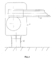
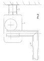
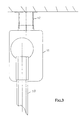
- the electromechanical barrier represented includes a revolving bar 10, which can be straight or at an angle, have round, polygonal or some other shape in section, depending on needs.
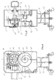
- the bar 10 is mounted on a body or frame 11, which holds the devices required to make the barrier operating and which may be in the form of a supporting post 12 to anchor it to the ground (Fig. 1), for example with a bracket 13 as shown in Figs 4 and 5, or a wall (Fig. 2) or a ceiling (Fig. 3).
- the bar 10 is attached to a rotating shaft 14 protruding from one side of the body 11, which is supported by bearings 15 and driven by an electric motor 16 with a first step-down gear 17 and a second step-down gear 18, which in the example illustrated are both the worm screw - worm wheel type.
- a release group 18' which is well known and does not require a description, works in conjunction with the rotating shaft 14.
- the electric motor 16 is powered and controlled by an electric actuator device 19 also placed in the body 11.
- a secondary rotating shaft 12 is provided, which is coupled to the rotating shaft 14 by means of a driving gear 21.
- One or two balancing springs 22 are connected to the secondary shaft 20, each one housed in a separate box or housing 23 acting also as a means for supporting said secondary shaft.
- the balancing spring or springs 22 can be spiral, as shown in Figs. 4 and 5, helicoidal or of another type, each with one end 24 attached to the secondary shaft 20 and the other end anchored to the stationary box or housing 23.
- the group is such that when the bar is actuated to move from the open to the closed position, the spring or springs load balancing the effect of the weight of the bar itself; when the bar then passes from the closed to the open position the springs react, assisting the action of the power unit thus facilitating the movement of the bar.
Landscapes
- Engineering & Computer Science (AREA)
- Architecture (AREA)
- Civil Engineering (AREA)
- Structural Engineering (AREA)
- Transmission Devices (AREA)
- Gear Transmission (AREA)
- Glass Compositions (AREA)
Abstract
Description
Claims (5)
- An electromechanical barrier, comprisingcharacterised in that a secondary rotating shaft (20) housed in said body parallel to the bar rotating shaft (14), in that a driving gear (21) couples said rotating shaft (14) to said secondary shaft (20) so that one turn of the former corresponds to one turn in proportion of the latter, and in that one spring balancing means (22) is connected with said secondary shaft (20).a movable bar (10) fixed and turning with a rotating shaft (14) supported in a body or supporting frame,a power apparatus actuating the rotating shaft (14) by means of a reduction unit, powered and managed by electronic control,at least one spring balancing mean to balance the bar during its movements between an open and closed positions,
- The electromechanical barrier according to claim 1, wherein the driving gear between the bar rotating shaft (14) and the secondary shaft (20) includes gearwheels meshing to each other.
- The electromechanical barrier according to claim 1, wherein the secondary shaft (20) operates in union with one or more balancing springs (22) , each one having one end fixed to said secondary shaft and the other anchored to a stationary means.
- The electromechanical barrier according to claim 3, wherein each balancing spring (22) is placed in a stationary box or housing which helps to support the rotating secondary shaft.
- The electromechanical barrier according to the previous claims, wherein each balancing spring (22) is spiral, helicoidal or of another spring type.
Applications Claiming Priority (4)
| Application Number | Priority Date | Filing Date | Title |
|---|---|---|---|
| ITBS20010079 | 2001-09-24 | ||
| IT2001BS000079U ITBS20010079U1 (en) | 2001-09-24 | 2001-09-24 | ELECTROMECHANICAL BARRIER |
| ITBS20010079U | 2001-09-24 | ||
| US10/391,660 US20040182005A1 (en) | 2001-09-24 | 2003-03-18 | Electromechanical barrier |
Publications (2)
| Publication Number | Publication Date |
|---|---|
| EP1295992A2 true EP1295992A2 (en) | 2003-03-26 |
| EP1295992A3 EP1295992A3 (en) | 2003-12-03 |
Family
ID=33477813
Family Applications (1)
| Application Number | Title | Priority Date | Filing Date |
|---|---|---|---|
| EP02077876A Withdrawn EP1295992A3 (en) | 2001-09-24 | 2002-07-16 | Electromechanical barrier |
Country Status (3)
| Country | Link |
|---|---|
| US (1) | US20040182005A1 (en) |
| EP (1) | EP1295992A3 (en) |
| IT (1) | ITBS20010079U1 (en) |
Cited By (6)
| Publication number | Priority date | Publication date | Assignee | Title |
|---|---|---|---|---|
| EP1967652A1 (en) * | 2007-03-05 | 2008-09-10 | Rib S.r.l. | Electromechanical barrier |
| WO2010133764A1 (en) * | 2009-05-18 | 2010-11-25 | Pg Effect Oy | Apparatus for balancing an object to be reciprocated in a vertical plane along a circular orbit |
| FR3042799A1 (en) * | 2015-10-27 | 2017-04-28 | A2C - Pop Up Concept | DEVICE FOR RESERVING PARKING SPACE AND PROTECTING THE BODYWORK OF A GROUND VEHICLE |
| WO2017072456A1 (en) * | 2015-10-27 | 2017-05-04 | A2C - Pop Up Concept | Device for reserving a parking space and protecting the bodywork of a land vehicle and car park comprising same |
| DE102019114513A1 (en) | 2018-05-30 | 2019-12-05 | Peter Fasel | barrier system |
| CN112235299A (en) * | 2020-10-14 | 2021-01-15 | 杭州海康威视数字技术股份有限公司 | Data encryption and decryption method, device, equipment, system and medium |
Families Citing this family (3)
| Publication number | Priority date | Publication date | Assignee | Title |
|---|---|---|---|---|
| WO2005013901A2 (en) * | 2003-07-31 | 2005-02-17 | Isis Pharmaceuticals, Inc. | Oligomeric compounds and compositions for use in modulation of small non-coding rnas |
| US7818920B2 (en) * | 2007-11-06 | 2010-10-26 | Causey Lynn R | Barrier gate with torque limiter |
| US8601739B2 (en) * | 2011-09-02 | 2013-12-10 | Siemens Rail Automation Corporation | Gate arm saver |
Family Cites Families (19)
| Publication number | Priority date | Publication date | Assignee | Title |
|---|---|---|---|---|
| US3839826A (en) * | 1973-05-15 | 1974-10-08 | R Ries | Power or manually operable gate |
| US3914902A (en) * | 1974-07-01 | 1975-10-28 | Hardware Specialties Sales Co | Turnstile |
| US3964704A (en) * | 1974-09-23 | 1976-06-22 | Harmon Industries, Inc. | Operating mechanism for railroad crossing gate |
| US4035955A (en) * | 1975-01-23 | 1977-07-19 | David Burnett | Boom gate |
| US3993975A (en) * | 1975-05-30 | 1976-11-23 | Long Jr Alvin W | Automatic parking lot gate |
| US4434578A (en) * | 1982-06-17 | 1984-03-06 | Rumpz Raphael J | Automatic traffic control gate |
| US4658543A (en) * | 1985-07-03 | 1987-04-21 | Carr Frederick J | Swinging lift gate |
| US4779379A (en) * | 1987-02-09 | 1988-10-25 | The Gatemaster Corporation | Gate operator |
| DE3715936A1 (en) * | 1987-05-13 | 1988-12-01 | Magnetic Elektromotoren Gmbh | DRIVING DEVICE FOR BARRIERS OD. DGL. |
| GB9005921D0 (en) * | 1990-03-16 | 1990-05-09 | Apt Controls Ltd | Traffic control barrier |
| US5136810A (en) * | 1991-05-30 | 1992-08-11 | Dewitt Iii Frank A | Parking gate |
| US5288164A (en) * | 1992-01-07 | 1994-02-22 | Nasatka Ralph G | Combined vehicle barrier |
| US5299882A (en) * | 1992-06-02 | 1994-04-05 | Sayers Donald L | Mechanically actuated barrier system |
| FR2718165B1 (en) * | 1994-03-30 | 1996-06-21 | Roger Chatel | Device for rotating a movable barrier. |
| AT402311B (en) * | 1995-03-20 | 1997-04-25 | Skidata Gmbh | SHUT-OFF DEVICE |
| DE19712333A1 (en) * | 1996-03-25 | 1997-11-06 | Froh Carl Gmbh | Barrier for entry roads, as for parking lots or similar |
| BR9714550A (en) * | 1997-07-17 | 2000-03-21 | Magnetic Autocontrol Gmbh | Activation device for a blocking gate. |
| GB9827241D0 (en) * | 1998-12-10 | 1999-02-03 | Baker Joseph P W | Barrier apparatus |
| US6470626B2 (en) * | 2001-01-17 | 2002-10-29 | Mtr, Inc. | Gate release mechanism with detent and plunger, and gate incorporating same |
-
2001
- 2001-09-24 IT IT2001BS000079U patent/ITBS20010079U1/en unknown
-
2002
- 2002-07-16 EP EP02077876A patent/EP1295992A3/en not_active Withdrawn
-
2003
- 2003-03-18 US US10/391,660 patent/US20040182005A1/en not_active Abandoned
Cited By (6)
| Publication number | Priority date | Publication date | Assignee | Title |
|---|---|---|---|---|
| EP1967652A1 (en) * | 2007-03-05 | 2008-09-10 | Rib S.r.l. | Electromechanical barrier |
| WO2010133764A1 (en) * | 2009-05-18 | 2010-11-25 | Pg Effect Oy | Apparatus for balancing an object to be reciprocated in a vertical plane along a circular orbit |
| FR3042799A1 (en) * | 2015-10-27 | 2017-04-28 | A2C - Pop Up Concept | DEVICE FOR RESERVING PARKING SPACE AND PROTECTING THE BODYWORK OF A GROUND VEHICLE |
| WO2017072456A1 (en) * | 2015-10-27 | 2017-05-04 | A2C - Pop Up Concept | Device for reserving a parking space and protecting the bodywork of a land vehicle and car park comprising same |
| DE102019114513A1 (en) | 2018-05-30 | 2019-12-05 | Peter Fasel | barrier system |
| CN112235299A (en) * | 2020-10-14 | 2021-01-15 | 杭州海康威视数字技术股份有限公司 | Data encryption and decryption method, device, equipment, system and medium |
Also Published As
| Publication number | Publication date |
|---|---|
| EP1295992A3 (en) | 2003-12-03 |
| ITBS20010079U1 (en) | 2003-03-24 |
| US20040182005A1 (en) | 2004-09-23 |
Similar Documents
| Publication | Publication Date | Title |
|---|---|---|
| US4638597A (en) | Modular automatic gate opener | |
| CN101465220B (en) | Medium- and high-voltage switch device and operation mechanism thereof | |
| US5280258A (en) | Spring-powered operator for a power circuit breaker | |
| US20040182005A1 (en) | Electromechanical barrier | |
| CN101425401A (en) | Electromechanical actuator equipped with a mechanical brake of the helical spring type | |
| WO2001083247A2 (en) | Rod on rail power liftgate drive mechanism | |
| CA2582254C (en) | Electrically driven entryway actuation system | |
| US20030205000A1 (en) | Electric door operator | |
| CN1970984A (en) | Actuator for a movable part | |
| JPS594712A (en) | Automatic vehicle blocking machine | |
| US6009670A (en) | Gate operator for vertical gate movement | |
| KR101015637B1 (en) | Door closer | |
| KR100919456B1 (en) | Crossing gate for vehicle automatocally opening in powerfailure | |
| US4624076A (en) | Door opener | |
| EP0118081B1 (en) | Actuating device for a vehicle door | |
| US5146800A (en) | Traffic control barrier | |
| US7290823B2 (en) | Closing unit | |
| EP0693609A1 (en) | Actuation for a turning sash | |
| CA2385005C (en) | Electric door operator | |
| EP1258591A1 (en) | Electric door operator | |
| CN1014102B (en) | Tensioning mechanism of electric switch transmission spring | |
| EP1309811B1 (en) | Actuator for valves | |
| EP1967652A1 (en) | Electromechanical barrier | |
| RU2760100C1 (en) | Barrier | |
| EP1783297A1 (en) | Incline-adjustable support assembly for an awning case |
Legal Events
| Date | Code | Title | Description |
|---|---|---|---|
| PUAI | Public reference made under article 153(3) epc to a published international application that has entered the european phase |
Free format text: ORIGINAL CODE: 0009012 |
|
| AK | Designated contracting states |
Kind code of ref document: A2 Designated state(s): AT BE BG CH CY CZ DE DK EE ES FI FR GB GR IE IT LI LU MC NL PT SE SK TR Designated state(s): AT BE BG CH CY CZ DE DK EE ES FI FR GB GR IE IT LI LU MC NL PT SE SK TR |
|
| AX | Request for extension of the european patent |
Extension state: AL LT LV MK RO SI |
|
| PUAL | Search report despatched |
Free format text: ORIGINAL CODE: 0009013 |
|
| AK | Designated contracting states |
Kind code of ref document: A3 Designated state(s): AT BE BG CH CY CZ DE DK EE ES FI FR GB GR IE IT LI LU MC NL PT SE SK TR |
|
| AX | Request for extension of the european patent |
Extension state: AL LT LV MK RO SI |
|
| AKX | Designation fees paid | ||
| REG | Reference to a national code |
Ref country code: DE Ref legal event code: 8566 |
|
| STAA | Information on the status of an ep patent application or granted ep patent |
Free format text: STATUS: THE APPLICATION IS DEEMED TO BE WITHDRAWN |
|
| 18D | Application deemed to be withdrawn |
Effective date: 20040604 |