EP1295843B1 - Cap opening system - Google Patents
Cap opening system Download PDFInfo
- Publication number
- EP1295843B1 EP1295843B1 EP02021060A EP02021060A EP1295843B1 EP 1295843 B1 EP1295843 B1 EP 1295843B1 EP 02021060 A EP02021060 A EP 02021060A EP 02021060 A EP02021060 A EP 02021060A EP 1295843 B1 EP1295843 B1 EP 1295843B1
- Authority
- EP
- European Patent Office
- Prior art keywords
- cap
- container body
- opening system
- handling apparatus
- rotation
- Prior art date
- Legal status (The legal status is an assumption and is not a legal conclusion. Google has not performed a legal analysis and makes no representation as to the accuracy of the status listed.)
- Expired - Lifetime
Links
- 230000007246 mechanism Effects 0.000 claims description 54
- 230000003287 optical effect Effects 0.000 claims description 48
- 230000002093 peripheral effect Effects 0.000 claims description 9
- 238000006243 chemical reaction Methods 0.000 claims description 2
- 238000013016 damping Methods 0.000 claims description 2
- 238000001514 detection method Methods 0.000 description 13
- 238000000034 method Methods 0.000 description 12
- 230000008569 process Effects 0.000 description 11
- 210000000078 claw Anatomy 0.000 description 5
- 230000008878 coupling Effects 0.000 description 5
- 238000010168 coupling process Methods 0.000 description 5
- 238000005859 coupling reaction Methods 0.000 description 5
- 230000008901 benefit Effects 0.000 description 4
- 238000012790 confirmation Methods 0.000 description 2
- 238000010586 diagram Methods 0.000 description 2
- 238000007781 pre-processing Methods 0.000 description 2
- 230000009471 action Effects 0.000 description 1
- 230000003213 activating effect Effects 0.000 description 1
- 238000007792 addition Methods 0.000 description 1
- 230000015572 biosynthetic process Effects 0.000 description 1
- 230000037237 body shape Effects 0.000 description 1
- 230000006835 compression Effects 0.000 description 1
- 238000007906 compression Methods 0.000 description 1
- 239000007788 liquid Substances 0.000 description 1
- 239000000463 material Substances 0.000 description 1
- 239000007769 metal material Substances 0.000 description 1
- 239000011347 resin Substances 0.000 description 1
- 229920005989 resin Polymers 0.000 description 1
- 230000004044 response Effects 0.000 description 1
- 230000000630 rising effect Effects 0.000 description 1
Images







Classifications
-
- B—PERFORMING OPERATIONS; TRANSPORTING
- B67—OPENING, CLOSING OR CLEANING BOTTLES, JARS OR SIMILAR CONTAINERS; LIQUID HANDLING
- B67B—APPLYING CLOSURE MEMBERS TO BOTTLES JARS, OR SIMILAR CONTAINERS; OPENING CLOSED CONTAINERS
- B67B7/00—Hand- or power-operated devices for opening closed containers
- B67B7/02—Hand- or power-operated devices for opening closed containers for removing stoppers
-
- B—PERFORMING OPERATIONS; TRANSPORTING
- B67—OPENING, CLOSING OR CLEANING BOTTLES, JARS OR SIMILAR CONTAINERS; LIQUID HANDLING
- B67B—APPLYING CLOSURE MEMBERS TO BOTTLES JARS, OR SIMILAR CONTAINERS; OPENING CLOSED CONTAINERS
- B67B7/00—Hand- or power-operated devices for opening closed containers
- B67B7/18—Hand- or power-operated devices for opening closed containers for removing threaded caps
- B67B7/182—Hand- or power-operated devices for opening closed containers for removing threaded caps power-operated
Definitions
- a cap opening apparatus used in a sample preprocessing system or the like is an apparatus which automatically removes a cap provided in a container such as a test tube or the like.
- the FR-A-2 014 953 for example describes a cap opening system for automatically opening a screw cap of a container which includes a container body and the cap attached thereto.
- This system comprises a container body handling apparatus for holding the container body of the container to raise and lower it, a cap handling apparatus arranged above the container body handling apparatus for grasping and then opening the cap of the container when the container body is raised and positioning means for positioning the cap with respect to the cap opening apparatus, in particular with respect to the cap handling apparatus.
- a further object of the present invention is to provide a cap opening system equipped with a cap handling apparatus in which the cap is rotated after a constant grasping force is produced irrespective of the size of the cap to be grasped.
- the first sensor is positioned above the container body at least before the cap opening operation is carried out. In this case, it is also preferred that the first sensor is positioned above the container body again when the cap opening operation has been carried out.
- the reference level is the top surface of the cap. This is effective because detection of the top surface can be made relatively easily, and because the cap is grasped at its middle portion below the top surface.
- the holding mechanisms 64, 66 described above are mounted respectively to the stages 30R, 30L.
- These holding mechanisms 64, 66 respectively include sliding blocks 68, 70 and holding members 76, 78 having V-shaped chucking grooves formed therein.
- the sliding blocks 68, 70 respectively slide up and down along a rail 46B provided on the frame 46, and a rail (not shown in the drawing) provided on the frame 48.
- the sliding blocks 68, 70 respectively include coupling portions 68A, 70A which are fixed to the belts 60, 62. Accordingly, when the belts 60, 62 are moved, the holding mechanisms 64, 66 move up or down.
- the nut member 112 is provided so as to be raised or lowered freely with respect to the inner frame 108, but there is a restriction on its rotation (in other words, the nut member 112 is constructed so that when the internal unit 102 is rotated, the nut member 112 is also rotated therewith).
- a pin (not shown in the drawing) can be provided on the nut member 112, and a groove (not shown in the drawing) to which the pin is movably engaged can be formed in the inner frame 108 in the up and down direction. Namely, by engaging the pin into the groove, the pin is allowed to move up and down, and the rotation of the nut member 112 is transmitted to the inner frame 108 via the pin.
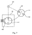
- two rotation rollers 136, 138 supported by two arms 136A, 138A are provided above the disposal box 24.
- the distance between these two rotation rollers 136, 138 is set to be slightly shorter than the length of one side of the triangular plate. Accordingly, as shown in Fig. 8(A), when the cap opening head 16 is rotated about the rotation axis 202 and positioned above the disposal box 24, the rotation preventing member 111 rotates in accordance with the rotation angle of the rotation preventing member 111, and this rotation is finally prevented by the abutment with the two rotation rollers 136, 138. This is shown in Fig.
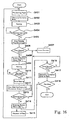
- Step S104 a judgment of whether or not the top surface of the cap has been detected, namely, whether or not the optical beam 203 has been interrupted during the raising step is carried out by the second sensor (i.e., the light emitting element 86 and the light receiving element 84) shown in Fig. 3.
- the second sensor i.e., the light emitting element 86 and the light receiving element 84
- the output signal of the second sensor is ON, namely, in the case where the top surface of the cap is detected
- the raising of the container body 12 by the container body grasping unit 14 is stopped at Step S105. This stopping position is then utilized as the origin height.
- Step S106 an object detection is carried out from above the container body 12 by the first sensor 18 shown in Fig. 1, and in the case where the presence of the cap 13 can not be confirmed, the error process at Step S107 is carried out.
- the rotary plate 20 is rotated 90 degrees counterclockwise, whereby the cap opening head 16 is positioned above the cap opening position 200 as shown in Fig. 1.
- Step S110 a cap opening operation is carried out by the cap opening head 16.
- the container body 12 is lowered by a predetermined distance downward by the container body grasping unit 14. Then, the container body 12 is finally lowered to the same height as the stopping position in Step S105.
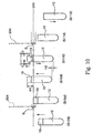
- Fig. 10 shows the main operations in the process represented by the flow chart of Fig.9a.
- the container body 12 is raised upward at Step S103, and this raising of the container body 12 is stopped when the top surface of the cap 13 is detected at Step S114.
- an object detection is carried out by the optical beam 204 at Step S106, and in this case, for example, an object detection is carried out within a predetermined range G with the optical beam 203 as a reference level.
- Step S109 the container body 12 is raised by a predetermined distance H1 upward, and the cap 13 is positioned properly with respect to the cap opening head 16.
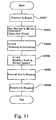
- Fig. 11 shows a flowchart of the operations of the cap opening head at Step S110 in Fig. 9
- Fig. 12 shows a flowchart of the operations of the cap opening head at the time the cap is discarded at Step S113 in Fig. 9.
- Step S201 rotation of the rotation shaft 110 is begun in the cap opening head 16 shown in Fig. 6.
- Step S202 the nut member 112 begins to move in the advancing direction, and in accordance with this movement, the clamping mechanism 106 carries out a grasping movement. Namely, the claws 130 are moved toward each other. Then, when the grasping of the cap 13 is completed, namely, when the advancing movement of the nut member 112 is stopped, the biasing force F1 exerted by the plurality of springs 136 is balanced with the upward force F2 exerted on the nut member 112 by the driving ends 128 as shown in Step S203.
- Step S204 when rotation of the rotation shaft 110 is further continued, F2 becomes larger than F1 as shown in Step S204, whereby the shoulder portion 110D of the rotation shaft 110 pushes the brake plate 131 upward.
- Step S205 when the rotation restricted state of the internal unit 102 is released, the internal unit 102 is allowed to do rotary movement in accordance with the rotation of the rotation shaft 110. Then, after a predetermined number of rotations is carried out, the operation of the driving motor is stopped, whereby the rotation of the internal unit 102 is also stopped as shown in Step S206.
- Step S302 in Fig. 12 rotational force in the reverse direction is transmitted to the rotation shaft by the driving motor, and then as shown in Step S303, the rotation shaft 110 is returned to its original position, and in accordance with this, the nut member 112 is retracted backward and returned to its original position. Then, during this process, as shown by Step S304, the cap being held up to now is released from the clamping mechanism 106 and falls into the inside of the disposal box 24. After that, the reverse rotation operation of the driving motor is stopped as shown in Step S305.
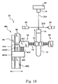
- Fig. 13 shows the structure of a part of the container body grasping unit 14 (in particular, the structure which is different from the embodiment shown in Fig. 3).
- the container body grasping unit 14 has two stages, only one stage 30L is shown in Fig. 13. The other stage has the same structure as that of the stage 30L.
- the stage 30L includes an erected frame 48 having a rail 48B.
- An upper slide block 401 and a lower slide block 402 are slidably mounted to the rail 48B.
- a spring 404 which is a compression spring is provided between the upper slide block 401 and the lower slide block 402 so that the upper slide block 401 is biased upward with respect to the lower slide block 402 to the extent of a certain distance.
- the lower slide block 402 is formed with a coupling portion 402A, and the lower side block 402 is coupled to a belt 60 by means of the coupling portion 402A.
- the lower slide block 402 is a slide block of a driving side
- the upper slide block 401 is a slide block of a driven side, and they are normally moved up and down together.
- the upper slide block 401 is provided with an abutment sensor 406. As described later, positioning of the cap 13 (formation of abutment state) is carried out before opening the cap. In this case, when the upward movement of the upper slide block 401 is forcedly stopped, a contact 402B formed on the lower slide block 402 contacts with the abutment sensor 406 due to the upward movement of the lower slide block 402. Then, a control section not shown in the drawings recognizes the abutment of the cap based on an output signal from the abutment sensor 406, and at the same time, stops the driving of the belt 60. By such abutment state and the control for the raising movement, the cap 13 can be properly positioned with respect to the cap opening head.
- Fig. 13 shows the state that the first sensor 18 is at the rotational position B shown in Fig. 1.
- the light emitting element 86 and the light receiving element 84 which constitute the second sensor are provided at a predetermined height.
- This second sensor forms the optical beam 203.
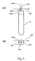
- the optical beams 203 is interrupted by the cap 13, and the reference surface (that is, the top surface of the cap or the top surface of the protruding portion) of the cap 13 is detected by the interruption of the beam.
- the raising movement of the container body 12 is stopped at that time, and in this stopped state, detection for the presence or absence of an object is carried out by the first sensor 18.
- the first sensor 18 forms a vertical optical beam aligned with the center of the cap 13 to detect the presence or absence of an object within a predetermined height range along the optical beam 204 with using the height of the optical beam 203 as a reference level. In this case, if the cap 13 exists, the cap 13 is detected by the reflection of the beam. On the other hand, if there is no cap 13, that is if the cap 13 is not provided in the container body 12, no object is detected. In this way, it is possible to confirm the presence of the cap before the cap opening operation, thereby enabling to perform the cap opening operation with high reliability.
- This advantage is the same as the first embodiment shown in Fig. 1 to Fig. 8.
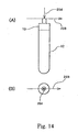
- Fig. 14 shows the relation between the optical beam 203 and the optical beam 204.
- the optical beam 203 is set so as to pass through the center of the cap 13, and the optical beam 204 is also set so as to align with the center of the cap 13. Therefore, in the case of the cap 13 having the protruding portion as shown in Fig. 14, the top surface of the protruding portion is detected with the respective optical beams 203 and 204. In this embodiment, only detection of the presence or absence of the cap is needed, and the positioning of the cap 13 with respect to the cap opening head is carried out by a separate means. Therefore, there is no problem even if the optical beams 203 and 204 as shown in Fig. 14 are used. Of course, it goes without saying that the technique as shown in Figs. 4 and 5 may be adopted.
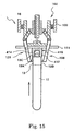
- Fig. 15 shows the structure of a part of the cap opening head of this embodiment (in particular, the structure which is different from the embodiment shown in Fig. 6).
- a clamp mechanism 106 is constructed from a plurality of arms 120. In a space surrounded by these arms, that is a space defined below the cap opening head, a cap receiving member 410 is fixedly provided.
- the cap receiving member 410 may be formed of, for example, a metallic material or a resin material, and in the example shown in the drawing, it is fixedly mounted to the rotation preventing member 111.
- the cap receiving member 410 includes a concave part 414 which corresponds to the central portion of the cap and a cylindrical extending part 412 which is formed around the concave part 414 so as to extend downward.
- this embodiment when the container body 12 is raised upward by the container body handling apparatus, the tip surface (in particular, the peripheral portion thereof) 13A of the cap 13 comes to abutment with the lower surface (abutment surface) of the extending part 412, so that the raising movement of the container body is forcedly stopped. At this time, the cap is positioned with respect to the cap opening head 16 at a proper height, that is it becomes possible to properly clamp the middle portion (circumferential surface) 13B of the cap 13.
- this embodiment has an advantage in that it is possible to determine the clamping position (height) based on the reference surface which is the top surface of the cap even though different thickness of the cap and different length of the container body 12.
- the cap receiving member 410 is formed with the concave part 414. Therefore, even in the case of a specific type cap in which a protruding portion is formed on the central portion of the top surface of the cap, positioning of the cap 13 can be carried out properly by receiving the protruding portion 13C into the concave part 414.
- Other structures and operations of this embodiment are basically the same as those of the embodiment shown in Fig. 6.
- Steps S401 to S408 are basically the same as Steps S101 to S108 in Fig. 9, and Step S412 to S418 in Fig 16 are basically the same as Steps S110 to S116 in Fig. 9. Therefore, in the following, a description will be made particularly with reference to Steps S409 to S411 in Fig. 16.
- the cap opening system of the present invention makes it possible to realize a simple structure which can grasp a cap and then rotate it. Further, according to the present invention, it is possible to create a cap grasping force and a rotation force by a single driving source. Furthermore, according to the present invention, a cap is always rotated after a constant grasping force is exerted irrespective of sizes of caps.
Landscapes
- Engineering & Computer Science (AREA)
- Mechanical Engineering (AREA)
- Automatic Analysis And Handling Materials Therefor (AREA)
- Devices For Opening Bottles Or Cans (AREA)
- Sealing Of Jars (AREA)
Description
Claims (31)
- A cap opening system for automatically opening a cap (13) of a container which includes a container body (12) and the cap (13) attached thereto, the system comprising:and wherein the cap handling apparatus (16) comprising a plurality of arms (120) provided on the rotary unit (102) for grasping the cap (13), wherein the cam member (112) is adapted to move in an advancing direction to cause the plurality of arms (120) perform the grasping operation;a container body handling apparatus (14) for holding the container body (12) of the container to raise and lower it;a cap handling apparatus (16) arranged above the container body handling apparatus (14) for grasping and then opening the cap (13) of the container when the container body (12) is raised; andpositioning means (84, 86, 203, 18, 204, 410) for positioning the cap (13) with respect to the cap handling apparatus (16), wherein the cap handling apparatus (16) comprising:a base frame (100);a rotary unit (102) rotatably provided with respect to the base frame (100) comprising:a rotary frame (108);a rotation shaft (110) which is a shaft rotatably driven and provided so as to be capable of advancing or retracting with respect to the rotary frame (108) and being biased toward the advancing direction; anda cam member (112);
CHARACTERIZED IN THAT the cap handling apparatus (16) comprises:wherein by the forward rotational movement of the rotation shaft (110), the plurality of arms (12) first perform the grasping operation and then the plurality of arms (120) are rotated.a brake mechanism (104) for restricting the rotation of the rotary unit (102), wherein said.shaft (110) includes an engagement part (110D) which is to be engaged with the brake mechanism (104) to release its rotation restricted state at a retracting position thereof, and a screw part (110A), and wherein the cam member (112) is threaded onto the screw part (110A), and said cam member (112) is adapted to move in the advancing direction by the forward rotation of the rotation shaft (110) in the rotation restricted state of the rotary unit (102) to cause the plurality of arms (120) perform the grasping operation, and adapted to stop the advancing movement after the grasping operation has been completed to convert the forward rotational movement of the rotation shaft (110) into a retracting movement of the rotation shaft (110), - The cap opening system as claimed in claim 1, wherein the cam member (112) is formed with an inclined surface (114) on which a driving end (128) of each arm (120) slidably contacts, in which the driving ends (128) of the respective arms (120) are moved on the inclined surface (114) according to the advancing movement of the cam member (112) so that operating ends (130) of the respective arms (120) are operated so as to be closed.
- The cap opening system as claimed in claim 1, wherein the brake mechanism (104) comprises a brake plate (131), and biasing means (136) which biases the brake plate (131) in the advancing direction of the rotation shaft (110), wherein the rotation of the rotary unit (102) is being restricted during the state that the brake plate (131) is in contact with the rotary frame (108).
- The cap opening system as claimed in claim 1, wherein the brake plate (131) comes to release from the rotary frame (108) from the point of time that a force caused by the retracting movement of the rotation shaft (110) after the conversion exceeds the biasing force of the biasing means (136), thereby the rotation restricted state of the rotary frame (108) is released.
- The cap opening system as claimed in claim 1, further comprising rotation preventing means (111) for preventing rotation of the rotary unit (102) when the plurality of arms (120) are operated so as to release the grasping cap (13), wherein by the reverse rotation of the rotation shaft (110), the cam member (112) carries out the retracting movement with respect to the rotation shaft (110) and the rotation shaft (110) carries out the advancing movement.
- The cap opening system as claimed in claim 5, wherein the rotation preventing means (111) includes a polygonal member provided on the rotary unit (102), and a plurality of abutment members (136, 138) which abut on the polygonal member to prevent its rotation.
- The cap opening system as claimed in claim 1, wherein the rotary unit (102) includes a positioning member (410) on which the cap (13) is adapted to abut.
- The cap opening system as claimed in claim 1, wherein the cap has a reference surface, and the positioning means (410) positions the cap (13) with respect to the cap handling apparatus (16) basted on the reference surface of the cap (13).
- The cap opening system as claimed in claim 8, wherein the cap (13) has a top surface (13A) and the reference surface is the top surface (13A) of the cap (13).
- The cap opening system as claimed in claim 9, wherein said positioning means (410) includes a cap receiving member (410) to which the top surface of the cap is adapted to abut, said cap receiving member (410) being arranged underneath the cap handling apparatus (16) in which positioning of the cap (13) is carried out by the abutment of the top surface (13A) of the cap (13) against the cap receiving member (410).
- The cap opening system as claimed in claim 10, wherein said cap receiving member (410) has a central portion and a peripheral portion, in which a concave part (414) is formed in the central portion and an extending part (412) is formed in the peripheral portion thereof.
- The cap opening system as claimed in claim 11, wherein a protruding portion (13C) is formed on the central portion of the top surface (13A) of the cap (13), and the concave part (414) has size and shape that can receive the protruding portion (13C) therein.
- The cap opening system as claimed in claim 10, wherein the container body handling apparatus (14) includes an abutment detecting device for detecting abutment of the top surface (13A) of the cap (13) against the cap receiving member (410) and' a control section for stopping the raising operation of the container body (12) when the abutment detecting device detects the abutment.
- The cap opening system as claimed in claim 10, further comprising buffer means (404) for damping impact by the abutment when the top surface (13A) of the cap (13) abuts against the cap receiving member (410).
- The cap opening system as claimed in claim 1, wherein the positioning means includes a first sensor (18) which emits a vertical beam (204) along the raising and lowering path of the cap (13), a second sensor (83) which emits a horizontal beam (203) which intersects the raising and lowering path of the cap (13) at a predetermined height, and means for determining presence or absence of the cap (13) based on the outputs of the first and second sensors (18, 83).
- The cap opening system as claimed in claim 15, wherein the raising operation of the container body (12) is stopped when the horizontal optical beam (203) is interrupted, and in this state the presence or absence of an object within a predetermined range in height is detected utilizing the vertical optical beam (204).
- The cap opening system as claimed in claim 15, wherein the first sensor (18) is postioned above the container body (12) at least before the cap opening operation is carried out.
- The cap opening system as claimed in claim 17, wherein the first sensor (18) is positioned above the container body (12) again when the cap opening operation has been carried out.
- The cap opening system as claimed in claim 1, wherein the positioning means includes:a reference surface detector which detects a reference surface of the cap (13) of the container when the container body (12) is raised upward by the container body handling apparatus (14); andmeans for controlling the operations of the container body handling apparatus (14) and the cap handling apparatus (16) to position the cap (13) with respect to the cap handling apparatus (16) based on the detected reference surface.
- The cap opening system as claimed in claim 19, wherein the cap (13) has a top surface (13A) and the reference surface is the top surface (13A) of the cap (13).
- The cap opening system as claimed in claim 20, wherein the reference surface detector includes a light emitting element (86) and a light receiving element (84) arranged at opposite sides of the raising and lowering path of the cap (13) so that an optical beam (203) is run between the light receiving and light emitting elements (84, 86), in which the top suface (13A) of the cap (13) is detected utilizing the interruption of the optical beam (203) by the cap (13).
- The cap opening system as claimed in claim 21, wherein the top surface (13A) of the cap (13) has a central portion and a peripheral portion which is located at a position shifted from the central portion in the horizontal direction, in which the light receiving and light emitting elements (84, 86) are arranged so that the optical beam (203) runs across the peripheral portion, thereby enabling to detect the top surface (13A) of the cap (13) irrespective of the shape of the central portion of the top surface (13A) of the cap (13).
- The cap opening system as claimed in claim 19, wherein the control section sets the height at which the reference surface is detected by the reference surface detector (83, 203) as a reference level and then raises the container body (12) by a predetermined distance, thereby positioning the cap (13) with respect to the cap handling apparatus (16).
- The cap opening system as claimed in claim 19, further comprising a cap presence or absence detector (18, 204) for detecting presence or absence of the cap (13).
- The cap opening system as claimed in claim 24, wherein the cap presence or absence detector (18, 204) is positioned above the container body (12) at least before the cap opening operation is carried out.
- The cap opening system as claimed in claim 25, wherein the cap presence or absence detector (18, 204) is positioned above the container body (12) again when the cap opening operation has been carried out.
- The cap opening system as claimed in claim 26, wherein the cap presence or absence detector (18, 204) includes a reflection type optical sensor (18) which detects the presence or absence of an object within a predetermined range in height.
- The cap opening system as claimed in claim 1, wherein the container body handling apparatus (14) comprises:a pair of holding mechanisms (64, 66) which are arranged opposite to each other so as to be capable of advancing or retracting, for holding a container body (12) of a container which is supported by a rack from opposite sides of the container body (12); anda raising and lowering mechanism (34) for raising and lowering the pair of holding mechanisms (64, 66).
- The cap opening system as claimed in claim 1, further comprising:a movable member on which the cap handling apparatus (16) is mounted; andmeans for driving the movable member so as to position the cap handling apparatus (16) above the container body (12) which is held by the container body handling apparatus (16) when the cap (13) is to be while postitioning the cap handling apparatus (16) above a cap disposal section (24) when disposing of the cap (13).
- The cap opening system as claimed in claim 29, wherein the movable member includes a rotary plate (20) which is rotatable between a first angular position and a second angular position, in which the rotation angle of the rotary plate (20) is set at the first angular position when the cap (13) is to be opened and the rotation angle of the rotary plate (20) is set at the second angular position when disposing of the cap (13).
- The cap opening system as claimed in claim 30, wherein the cap presence or absence detector (18, 204) is mounted on the rotary plate (20) in which when the rotary plate (20) is in the first angular position, the cap presence or absence detector (18, 204) is positioned at its evacuated position, while when the rotary plate (20) is in the second angular position, the cap presence or absence detector (18, 204) is positioned above the container body (12) held by the container body handling apparatus (14).
Applications Claiming Priority (4)
| Application Number | Priority Date | Filing Date | Title |
|---|---|---|---|
| JP2001286354 | 2001-09-20 | ||
| JP2001286346A JP3950658B2 (en) | 2001-09-20 | 2001-09-20 | Opening system and opening method |
| JP2001286354A JP3752170B2 (en) | 2001-09-20 | 2001-09-20 | Handling device |
| JP2001286346 | 2001-09-20 |
Publications (3)
| Publication Number | Publication Date |
|---|---|
| EP1295843A2 EP1295843A2 (en) | 2003-03-26 |
| EP1295843A3 EP1295843A3 (en) | 2003-05-14 |
| EP1295843B1 true EP1295843B1 (en) | 2005-12-21 |
Family
ID=26622568
Family Applications (1)
| Application Number | Title | Priority Date | Filing Date |
|---|---|---|---|
| EP02021060A Expired - Lifetime EP1295843B1 (en) | 2001-09-20 | 2002-09-20 | Cap opening system |
Country Status (3)
| Country | Link |
|---|---|
| US (1) | US6871566B2 (en) |
| EP (1) | EP1295843B1 (en) |
| DE (1) | DE60208131T2 (en) |
Cited By (1)
| Publication number | Priority date | Publication date | Assignee | Title |
|---|---|---|---|---|
| GB2551991A (en) * | 2016-07-04 | 2018-01-10 | Stratec Biomedical Ag | Device for handling vials |
Families Citing this family (37)
| Publication number | Priority date | Publication date | Assignee | Title |
|---|---|---|---|---|
| US20050050999A1 (en) * | 2003-09-10 | 2005-03-10 | Kernan Colin Michael | Retention stand for a workpiece such as a jar |
| US7021597B2 (en) * | 2004-01-30 | 2006-04-04 | Vogt William R | Sensor alignment tool |
| JP3880586B2 (en) * | 2004-03-26 | 2007-02-14 | 株式会社アイディエス | Test tube stopper removal device |
| ES2265734B1 (en) * | 2004-10-27 | 2008-01-01 | Julio Abascal Diaz | PROCEDURE AND TUBE DISPUTING MACHINE. |
| EP1659090A1 (en) * | 2004-11-23 | 2006-05-24 | Kordia B.V. | Method and apparatus for detecting caps on test tubes |
| ES2226591B2 (en) * | 2004-11-23 | 2005-10-01 | Alt3 Enginyers, S.L. | MACHINE FOR AUTOMATIC EXTRACTION OF CONTAINER PLUGS. |
| JP4890998B2 (en) * | 2006-08-22 | 2012-03-07 | 株式会社日立ハイテクノロジーズ | Sample processing system |
| US8703492B2 (en) | 2007-04-06 | 2014-04-22 | Qiagen Gaithersburg, Inc. | Open platform hybrid manual-automated sample processing system |
| US7985375B2 (en) * | 2007-04-06 | 2011-07-26 | Qiagen Gaithersburg, Inc. | Sample preparation system and method for processing clinical specimens |
| US7409809B1 (en) * | 2007-04-10 | 2008-08-12 | Lars Degen | Automatic test tube decapping device |
| US9953141B2 (en) | 2009-11-18 | 2018-04-24 | Becton, Dickinson And Company | Laboratory central control unit method and system |
| US8684426B2 (en) | 2010-07-13 | 2014-04-01 | Richard Joseph Morales, JR. | Method and apparatus for installing alarm systems and door locks |
| US10113332B2 (en) | 2010-07-13 | 2018-10-30 | Punch Point Tools, L.L.C. | Method for installing door locks |
| EP2538225A1 (en) * | 2011-06-20 | 2012-12-26 | F. Hoffmann-La Roche AG | System for processing closed sample tubes |
| WO2013002216A1 (en) * | 2011-06-30 | 2013-01-03 | 株式会社日立ハイテクノロジーズ | Stopper opening/closing mechanism and automatic analysis system provided therewith |
| DE102011055899B4 (en) * | 2011-11-30 | 2013-11-21 | Andreas Hettich Gmbh & Co. Kg | Method and device for handling sample containers |
| RU2629611C9 (en) * | 2013-06-27 | 2017-10-26 | Ханчжоу Янгсан Интеллиджент Иквипмент Ко., Лтд. | Winding machine |
| JP6190237B2 (en) * | 2013-10-15 | 2017-08-30 | 川崎重工業株式会社 | ROBOT HAND, ROBOT, AND WORK Rotation Operation Method By Robot |
| JP5949739B2 (en) | 2013-12-13 | 2016-07-13 | 株式会社安川電機 | Robot system, container opening method, and workpiece manufacturing method |
| EP2886508B1 (en) * | 2013-12-20 | 2016-04-13 | CTC Analytics AG | Actuating device for screw-on cap |
| JPWO2015111526A1 (en) * | 2014-01-27 | 2017-03-23 | 株式会社日立ハイテクノロジーズ | Automatic analyzer |
| WO2015149060A2 (en) | 2014-03-28 | 2015-10-01 | Punch Point Tools, L.L.C. | Method and apparatus for installing alarm systems and door locks |
| US10551398B2 (en) * | 2015-04-27 | 2020-02-04 | Hitachi High-Technologies Corporation | Specimen container inclination correction mechanism, and method for controlling same |
| EP3196655B1 (en) | 2016-01-22 | 2020-11-25 | Roche Diagniostics GmbH | Laboratory sample container carrier handling apparatus and laboratory system |
| EP3196648B1 (en) * | 2016-01-22 | 2021-03-31 | Roche Diagniostics GmbH | Device for lifting a sample tube |
| EP3196654B1 (en) | 2016-01-22 | 2023-06-21 | Roche Diagnostics GmbH | Method and device for transferring sample tubes between a laboratory automation system and a sample archiving system |
| EP3560477A1 (en) * | 2016-03-15 | 2019-10-30 | Capsugel Belgium NV | Aseptic hard capsule sealing apparatus and methods |
| US10598637B2 (en) * | 2017-07-18 | 2020-03-24 | Perkinelmer Health Sciences, Inc. | Automated thermal desorption systems configured to determine sample tube orientation and/or cap presence, and related methods |
| US10816516B2 (en) | 2018-03-28 | 2020-10-27 | Perkinelmer Health Sciences, Inc. | Autosamplers and gas chromatographic systems and methods including same |
| JP7104923B2 (en) * | 2018-07-17 | 2022-07-22 | 国立大学法人神戸大学 | Cap attaching/detaching device, and sampling device and pretreatment device provided with the same |
| US11345519B2 (en) * | 2018-09-13 | 2022-05-31 | Entegris, Inc. | Automatable closure |
| CN112537740B (en) * | 2019-09-23 | 2025-03-25 | 北京北大维信生物科技有限公司 | Container cap collection device, system and method |
| CN114074906B (en) * | 2020-08-12 | 2024-01-30 | 系统科技公司 | Integrated coupling module and coupling system comprising the same |
| CN114368718A (en) * | 2021-12-20 | 2022-04-19 | 苏州镁伽科技有限公司 | Cap opening and closing mechanism, cap opening and closing device, liquid transfer apparatus, and cap opening and closing method |
| CN114368717A (en) * | 2021-12-20 | 2022-04-19 | 苏州镁伽科技有限公司 | Cap opening and closing device, pipetting apparatus, and cap closing method |
| JP7844906B2 (en) * | 2022-02-10 | 2026-04-14 | 株式会社島津製作所 | Cap attachment/detachment device and pretreatment device |
| CN115784128A (en) * | 2022-12-06 | 2023-03-14 | 中元汇吉生物技术股份有限公司 | Cap opening device and cap opening method |
Family Cites Families (8)
| Publication number | Priority date | Publication date | Assignee | Title |
|---|---|---|---|---|
| DE1939353A1 (en) | 1968-08-02 | 1970-02-12 | Dawson & Barfos Ltd | Device for unscrewing screw caps or screw stoppers from bottles or the like. |
| US4171650A (en) * | 1977-12-09 | 1979-10-23 | John Cardinal | Jar lid loosening device |
| PH24085A (en) * | 1986-04-30 | 1990-03-05 | Isabelita Hilaro Chen | Bottle closure opener |
| DE4102479A1 (en) | 1991-01-29 | 1992-07-30 | Kodak Ag | DEVICE FOR REMOVING PLUGS FROM CONTAINERS WITH A LIQUID |
| JP3203773B2 (en) | 1992-06-25 | 2001-08-27 | 株式会社日立製作所 | Automatic opening device |
| JPH06324051A (en) * | 1993-05-11 | 1994-11-25 | Olympus Optical Co Ltd | Plug opener |
| DE19512905A1 (en) * | 1995-04-06 | 1996-10-10 | Boehringer Mannheim Gmbh | Device for pulling or unscrewing closures from vessels |
| US6257091B1 (en) * | 1998-07-14 | 2001-07-10 | Bayer Corporation | Automatic decapper |
-
2002
- 2002-09-19 US US10/252,353 patent/US6871566B2/en not_active Expired - Lifetime
- 2002-09-20 EP EP02021060A patent/EP1295843B1/en not_active Expired - Lifetime
- 2002-09-20 DE DE60208131T patent/DE60208131T2/en not_active Expired - Lifetime
Cited By (1)
| Publication number | Priority date | Publication date | Assignee | Title |
|---|---|---|---|---|
| GB2551991A (en) * | 2016-07-04 | 2018-01-10 | Stratec Biomedical Ag | Device for handling vials |
Also Published As
| Publication number | Publication date |
|---|---|
| US6871566B2 (en) | 2005-03-29 |
| EP1295843A2 (en) | 2003-03-26 |
| US20030061911A1 (en) | 2003-04-03 |
| DE60208131D1 (en) | 2006-01-26 |
| EP1295843A3 (en) | 2003-05-14 |
| DE60208131T2 (en) | 2006-07-13 |
Similar Documents
| Publication | Publication Date | Title |
|---|---|---|
| EP1295843A2 (en) | Cap opener | |
| US6257091B1 (en) | Automatic decapper | |
| JP3752170B2 (en) | Handling device | |
| EP2793030B1 (en) | Test tube gripper, test tube labeling unit, and test tube preparing apparatus including the same | |
| JP7358381B2 (en) | Apparatus and method for monitoring relative movement | |
| JP6450275B2 (en) | Screw hole inspection device and screw hole inspection method | |
| US5289634A (en) | Valve assembling method and assembled valve checking method | |
| US20070036676A1 (en) | Method and system for picking and placing vessels | |
| KR102437369B1 (en) | Centrifugal Barrel Grinding Machine and Centrifugal Barrel Grinding Method | |
| FR2774975A1 (en) | DEVICE FOR TRANSFERRING AN OBJECT BETWEEN AT LEAST TWO LOCATIONS | |
| US5662567A (en) | Machine tool | |
| JP3950658B2 (en) | Opening system and opening method | |
| US6112391A (en) | Automatic loader-unloader for disk blank workpieces | |
| JPH08178606A (en) | Tap female screw hole inspection instrument and inspection device using the same | |
| US20080173660A1 (en) | Device for storing and dispensing endless machining belts for a robotic installation | |
| CN111646289B (en) | Cable drum fixture | |
| CN220854683U (en) | Device for inspecting containers | |
| JPH07185965A (en) | Rotating member automatic assembly equipment | |
| CA2227614C (en) | Vial closure remover | |
| JPH0780102B2 (en) | Method and device for tightening screw parts | |
| JP2005019761A (en) | Clamp device for checking the gripping of a disk-shaped object | |
| KR960009597B1 (en) | Apparatus of adjusting moving products for packaging | |
| JP2688554B2 (en) | Wafer abnormality detection device and wafer inspection method | |
| CN209736840U (en) | Ball rotating device | |
| SU1696006A1 (en) | Automatic machine for checking and sorting of sealing rings |
Legal Events
| Date | Code | Title | Description |
|---|---|---|---|
| PUAI | Public reference made under article 153(3) epc to a published international application that has entered the european phase |
Free format text: ORIGINAL CODE: 0009012 |
|
| AK | Designated contracting states |
Kind code of ref document: A2 Designated state(s): AT BE BG CH CY CZ DE DK EE ES FI FR GB GR IE IT LI LU MC NL PT SE SK TR |
|
| AX | Request for extension of the european patent |
Extension state: AL LT LV MK RO SI |
|
| PUAL | Search report despatched |
Free format text: ORIGINAL CODE: 0009013 |
|
| AK | Designated contracting states |
Designated state(s): AT BE BG CH CY CZ DE DK EE ES FI FR GB GR IE IT LI LU MC NL PT SE SK TR |
|
| AX | Request for extension of the european patent |
Extension state: AL LT LV MK RO SI |
|
| RIC1 | Information provided on ipc code assigned before grant |
Ipc: 7B 67B 7/02 A Ipc: 7B 67B 7/18 B |
|
| 17P | Request for examination filed |
Effective date: 20031027 |
|
| AKX | Designation fees paid |
Designated state(s): DE FR GB IT |
|
| 17Q | First examination report despatched |
Effective date: 20040211 |
|
| RTI1 | Title (correction) |
Free format text: CAP OPENING SYSTEM |
|
| GRAP | Despatch of communication of intention to grant a patent |
Free format text: ORIGINAL CODE: EPIDOSNIGR1 |
|
| GRAS | Grant fee paid |
Free format text: ORIGINAL CODE: EPIDOSNIGR3 |
|
| GRAA | (expected) grant |
Free format text: ORIGINAL CODE: 0009210 |
|
| AK | Designated contracting states |
Kind code of ref document: B1 Designated state(s): DE FR GB IT |
|
| REG | Reference to a national code |
Ref country code: GB Ref legal event code: FG4D |
|
| REF | Corresponds to: |
Ref document number: 60208131 Country of ref document: DE Date of ref document: 20060126 Kind code of ref document: P |
|
| ET | Fr: translation filed | ||
| PLBE | No opposition filed within time limit |
Free format text: ORIGINAL CODE: 0009261 |
|
| STAA | Information on the status of an ep patent application or granted ep patent |
Free format text: STATUS: NO OPPOSITION FILED WITHIN TIME LIMIT |
|
| 26N | No opposition filed |
Effective date: 20060922 |
|
| REG | Reference to a national code |
Ref country code: DE Ref legal event code: R082 Ref document number: 60208131 Country of ref document: DE Representative=s name: PATENTANWAELTE DR. SOLF & ZAPF, DE |
|
| REG | Reference to a national code |
Ref country code: DE Ref legal event code: R081 Ref document number: 60208131 Country of ref document: DE Owner name: UEDA JAPAN RADIO CO., LTD., UEDA, JP Free format text: FORMER OWNERS: ALOKA CO. LTD., MITAKA, TOKIO/TOKYO, JP; UEDA JAPAN RADIO CO., LTD., UEDA, NAGANO, JP Effective date: 20120120 Ref country code: DE Ref legal event code: R081 Ref document number: 60208131 Country of ref document: DE Owner name: HITACHI ALOKA MEDICAL, LTD., JP Free format text: FORMER OWNERS: ALOKA CO. LTD., MITAKA, TOKIO/TOKYO, JP; UEDA JAPAN RADIO CO., LTD., UEDA, NAGANO, JP Effective date: 20120120 Ref country code: DE Ref legal event code: R082 Ref document number: 60208131 Country of ref document: DE Representative=s name: PATENTANWAELTE DR. SOLF & ZAPF, DE Effective date: 20120120 Ref country code: DE Ref legal event code: R081 Ref document number: 60208131 Country of ref document: DE Owner name: HITACHI ALOKA MEDICAL, LTD., JP Free format text: FORMER OWNER: ALOKA CO. LTD., UEDA JAPAN RADIO CO., LTD., , JP Effective date: 20120120 Ref country code: DE Ref legal event code: R081 Ref document number: 60208131 Country of ref document: DE Owner name: UEDA JAPAN RADIO CO., LTD., UEDA, JP Free format text: FORMER OWNER: ALOKA CO. LTD., UEDA JAPAN RADIO CO., LTD., , JP Effective date: 20120120 |
|
| REG | Reference to a national code |
Ref country code: FR Ref legal event code: CD Owner name: HITACHI ALOKA MEDICAL, LTD Effective date: 20120301 |
|
| PGFP | Annual fee paid to national office [announced via postgrant information from national office to epo] |
Ref country code: FR Payment date: 20130912 Year of fee payment: 12 Ref country code: GB Payment date: 20130927 Year of fee payment: 12 |
|
| PGFP | Annual fee paid to national office [announced via postgrant information from national office to epo] |
Ref country code: IT Payment date: 20130923 Year of fee payment: 12 |
|
| PGFP | Annual fee paid to national office [announced via postgrant information from national office to epo] |
Ref country code: DE Payment date: 20131118 Year of fee payment: 12 |
|
| REG | Reference to a national code |
Ref country code: DE Ref legal event code: R119 Ref document number: 60208131 Country of ref document: DE |
|
| GBPC | Gb: european patent ceased through non-payment of renewal fee |
Effective date: 20140920 |
|
| REG | Reference to a national code |
Ref country code: DE Ref legal event code: R119 Ref document number: 60208131 Country of ref document: DE Effective date: 20150401 |
|
| REG | Reference to a national code |
Ref country code: FR Ref legal event code: ST Effective date: 20150529 |
|
| PG25 | Lapsed in a contracting state [announced via postgrant information from national office to epo] |
Ref country code: GB Free format text: LAPSE BECAUSE OF NON-PAYMENT OF DUE FEES Effective date: 20140920 Ref country code: DE Free format text: LAPSE BECAUSE OF NON-PAYMENT OF DUE FEES Effective date: 20150401 |
|
| PG25 | Lapsed in a contracting state [announced via postgrant information from national office to epo] |
Ref country code: IT Free format text: LAPSE BECAUSE OF NON-PAYMENT OF DUE FEES Effective date: 20140920 Ref country code: FR Free format text: LAPSE BECAUSE OF NON-PAYMENT OF DUE FEES Effective date: 20140930 |