EP1295788A2 - Hybrid power input quill for transmissions - Google Patents
Hybrid power input quill for transmissions Download PDFInfo
- Publication number
- EP1295788A2 EP1295788A2 EP02078142A EP02078142A EP1295788A2 EP 1295788 A2 EP1295788 A2 EP 1295788A2 EP 02078142 A EP02078142 A EP 02078142A EP 02078142 A EP02078142 A EP 02078142A EP 1295788 A2 EP1295788 A2 EP 1295788A2
- Authority
- EP
- European Patent Office
- Prior art keywords
- gear
- input shaft
- hybrid
- input
- pinion gear
- Prior art date
- Legal status (The legal status is an assumption and is not a legal conclusion. Google has not performed a legal analysis and makes no representation as to the accuracy of the status listed.)
- Granted
Links
Images
Classifications
-
- F—MECHANICAL ENGINEERING; LIGHTING; HEATING; WEAPONS; BLASTING
- F16—ENGINEERING ELEMENTS AND UNITS; GENERAL MEASURES FOR PRODUCING AND MAINTAINING EFFECTIVE FUNCTIONING OF MACHINES OR INSTALLATIONS; THERMAL INSULATION IN GENERAL
- F16H—GEARING
- F16H37/00—Combinations of mechanical gearings, not provided for in groups F16H1/00 - F16H35/00
- F16H37/02—Combinations of mechanical gearings, not provided for in groups F16H1/00 - F16H35/00 comprising essentially only toothed or friction gearings
- F16H37/06—Combinations of mechanical gearings, not provided for in groups F16H1/00 - F16H35/00 comprising essentially only toothed or friction gearings with a plurality of driving or driven shafts; with arrangements for dividing torque between two or more intermediate shafts
- F16H37/065—Combinations of mechanical gearings, not provided for in groups F16H1/00 - F16H35/00 comprising essentially only toothed or friction gearings with a plurality of driving or driven shafts; with arrangements for dividing torque between two or more intermediate shafts with a plurality of driving or driven shafts
-
- B—PERFORMING OPERATIONS; TRANSPORTING
- B64—AIRCRAFT; AVIATION; COSMONAUTICS
- B64C—AEROPLANES; HELICOPTERS
- B64C27/00—Rotorcraft; Rotors peculiar thereto
- B64C27/04—Helicopters
- B64C27/12—Rotor drives
-
- F—MECHANICAL ENGINEERING; LIGHTING; HEATING; WEAPONS; BLASTING
- F16—ENGINEERING ELEMENTS AND UNITS; GENERAL MEASURES FOR PRODUCING AND MAINTAINING EFFECTIVE FUNCTIONING OF MACHINES OR INSTALLATIONS; THERMAL INSULATION IN GENERAL
- F16H—GEARING
- F16H1/00—Toothed gearings for conveying rotary motion
- F16H1/02—Toothed gearings for conveying rotary motion without gears having orbital motion
- F16H1/04—Toothed gearings for conveying rotary motion without gears having orbital motion involving only two intermeshing members
- F16H1/12—Toothed gearings for conveying rotary motion without gears having orbital motion involving only two intermeshing members with non-parallel axes
- F16H1/14—Toothed gearings for conveying rotary motion without gears having orbital motion involving only two intermeshing members with non-parallel axes comprising conical gears only
-
- Y—GENERAL TAGGING OF NEW TECHNOLOGICAL DEVELOPMENTS; GENERAL TAGGING OF CROSS-SECTIONAL TECHNOLOGIES SPANNING OVER SEVERAL SECTIONS OF THE IPC; TECHNICAL SUBJECTS COVERED BY FORMER USPC CROSS-REFERENCE ART COLLECTIONS [XRACs] AND DIGESTS
- Y10—TECHNICAL SUBJECTS COVERED BY FORMER USPC
- Y10T—TECHNICAL SUBJECTS COVERED BY FORMER US CLASSIFICATION
- Y10T74/00—Machine element or mechanism
- Y10T74/19—Gearing
- Y10T74/19023—Plural power paths to and/or from gearing
- Y10T74/19074—Single drive plural driven
- Y10T74/19107—Nonparallel
-
- Y—GENERAL TAGGING OF NEW TECHNOLOGICAL DEVELOPMENTS; GENERAL TAGGING OF CROSS-SECTIONAL TECHNOLOGIES SPANNING OVER SEVERAL SECTIONS OF THE IPC; TECHNICAL SUBJECTS COVERED BY FORMER USPC CROSS-REFERENCE ART COLLECTIONS [XRACs] AND DIGESTS
- Y10—TECHNICAL SUBJECTS COVERED BY FORMER USPC
- Y10T—TECHNICAL SUBJECTS COVERED BY FORMER US CLASSIFICATION
- Y10T74/00—Machine element or mechanism
- Y10T74/19—Gearing
- Y10T74/19023—Plural power paths to and/or from gearing
- Y10T74/19074—Single drive plural driven
- Y10T74/19121—Concentric
-
- Y—GENERAL TAGGING OF NEW TECHNOLOGICAL DEVELOPMENTS; GENERAL TAGGING OF CROSS-SECTIONAL TECHNOLOGIES SPANNING OVER SEVERAL SECTIONS OF THE IPC; TECHNICAL SUBJECTS COVERED BY FORMER USPC CROSS-REFERENCE ART COLLECTIONS [XRACs] AND DIGESTS
- Y10—TECHNICAL SUBJECTS COVERED BY FORMER USPC
- Y10T—TECHNICAL SUBJECTS COVERED BY FORMER US CLASSIFICATION
- Y10T74/00—Machine element or mechanism
- Y10T74/19—Gearing
- Y10T74/19642—Directly cooperating gears
- Y10T74/1966—Intersecting axes
- Y10T74/19665—Bevel gear type
Definitions
- This invention relates generally to torque transmission systems, and specifically to lightweight transmission systems for use on rotorcraft, propeller-driven aircraft, and any other mechanically driven vehicle.
- a torque transmission system transfers power from an engine or motor to driven components of a device or vehicle.
- the proprotor transmission system transfers power from a turbine engine or other engine to the rotor or propeller of the rotorcraft or aircraft.
- a torque transmission system may direct power from one or more engines to a single driven component or to a number of driven components.
- the transmission system may also direct power to auxiliary systems.
- a proprotor transmission system often directs power from two turbine engines to a single rotor, auxiliary systems, and a secondary rotor.
- the rotational velocity of the driven component or components is significantly lower than the rotational velocity of the output of the driving engines or motors, thus the engine or motor rotational velocity must be reduced by the transmission system.
- torque is increased by the transmission system through a series of intermediate gear stages and shafts before final output to the driven component or components.
- large gears are required near the final output of the proprotor transmission system to handle the high torque being supplied to the proprotor(s).
- a typical main rotor transmission housing these large gears is often the heaviest gear box in a rotorcraft.
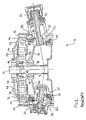
- FIGURE 1 is a full cross-sectional view of a prior art concentric face gear transmission 10 for a rotorcraft.
- Power from a turbine engine (not shown) is transferred via an input clutch 20 to an input shaft 21.
- An input spur pinion 23, connected to the input shaft 21, is meshed between a lower face gear 25 and an upper face gear 30.
- the combination of the input shaft 21 and the input spur pinion 23 will be referred to herein as an input quill.
- a lower thrust bearing 27 for the lower face gear 25 is located radially inwardly of the lower face gear 25.
- An upper thrust bearing 32 for the upper face gear 30 is located radially outwardly of the upper face gear 30.
- Torque from the input shaft 21 is split between the lower face gear 25 and the upper face gear 30 at a single stage gear meshing 34.
- the upper face gear 30 includes a web 36, connected to a female spline 38.
- the female spline 38 of the upper face gear 30 meshes with a male spline 41.
- the male spline 41 is connected to a sun gear 43.
- the sun gear 43 meshes with an inner radial portion of a planet gear 45.
- the planet gear 45 having an axis 47, rotates about the sun gear 43.
- An outer radial portion of the planet gear 45 meshes with a ring gear 49.
- the planet gears 45 are carried by a planet carrier 54, which rotates around a static support assembly 56. Power from the planet carrier 54 is used to drive the rotor of the aircraft through a main rotor drive shaft (not shown).
- FIGURE 1 The cross section of FIGURE 1 is taken through an input spur pinion 23 and an idler pinion 61.
- the input spur pinion 23 is located opposite a second input spur pinion (not shown) and the idler pinion 61 is located opposite a second idler pinion (not shown).
- the idler pinion 61 is connected to an idler shaft 60, which rotates around an axis that nearly intersects the axis of the static support assembly 56.
- the idler pinion 61 meshes with the lower face gear 25 and the upper face gear 30 at a single stage idler mesh 63.
- the idler pinion transfers and equalizes torque between the upper face gear 30 and the lower face gear 25.
- auxiliary power takeoffs for prior art transmissions as described herein, and other prior art utilize the main power transmission system to drive the auxiliary power system, increasing its weight, and requiring the space and complexity of additional gearing within the main power system to drive the auxiliary power takeoffs.
- the present invention presents a hybrid input quill that presents a lightweight, compact, and uncomplicated system for driving auxiliary power takeoffs while driving a main transmission.
- the hybrid input quill of the present invention includes at least one input pinion and one bevel pinion on a single input shaft allowing for two drive systems to be driven from the single hybrid input quill.
- the hybrid input quill may be incorporated into a concentric face gear transmission assembly where the input pinion gear drives the main power system of the device or vehicle, and the bevel gear drives auxiliary power systems.
- the bevel gear drives the auxiliary power system utilizing gearing outside of the primary power train reducing the weight, size, and complexity of the primary power train in the transmission.
- power is still transmitted to the auxiliary power system through the hybrid input quill when used in a multiengine configuration and the engine directly driving the hybrid input quill fails or is shut down.
- a clutch is utilized to disconnect the hybrid input quill from its input motor or engine, allowing the input quill to be driven by the balance of the transmission and other engine(s) or motor(s), providing extra safety or security in the drive system.
- the then-indirectly powered hybrid quill continues to drive its connected auxiliary system.
- the invention provides flexibility for shimming, spacing, or otherwise locating the gearing systems for the primary power and auxiliary power takeoffs independently, to provide for optimum gear mesh configuration.
- the location of the bevel pinion may be shimmed or positioned separate from the input pinion.
- the input pinion and the bevel pinion may be independently positioned to obtain optimum gear meshing.
- the location of the input pinion assembly may be shimmed or positioned relative to the main transmission. Shimming of the shaft pinion separate from shimming of the bevel pinion permits both the shaft pinion and the bevel pinion to be located optimally for their respective gearing systems.
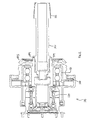
- FIGURE 2 is a cross section of a hybrid input quill 170.
- the hybrid input quill 170 includes an input shaft 121 with an attached shaft pinion gear 173.
- the input shaft 121 is driven by an engine or motor (not shown) through an input clutch 120.
- the input shaft 121 is supported by, and allowed to rotate within, the main quill bearings 181.
- Also attached to the input shaft 121 is a bevel pinion gear 175.
- the bevel pinion gear 175 is used to drive auxiliary systems, and the shaft pinion gear 173 is used to drive the main transmission (not shown).
- the bevel pinion gear 175, and the shaft pinion gear 173, are beveled, permitting the hybrid input quill 170 to be detachably mounted to the main transmission (not shown).
- the location of the shaft pinion gear 173 and the bevel pinion gear 175 can be adjusted as desired through the use of shims or alternative spacing devices.
- the location of the shaft pinion gear 173 in a presently preferred embodiment shown in FIGURE 2 may be adjusted through the shaft pinion shim(s) 177. Varying the thickness of the shaft pinion shim(s) 177 allows flexible positioning of the input shaft 121 (with the attached pinion gear 173) co-linear with its longitudinal axis, relative to the main transmission (not shown).
- the location of the bevel pinion gear 175 in a presently preferred embodiment can be adjusted relative to the shaft pinion gear 173 through using different thickness bevel pinion shim(s) 179.
- the bevel pinion shim(s) 179 are interposed between the input shaft 121 and the bevel pinion gear 175 permitting flexible, but precise, positioning of the bevel gear along the input shaft 121.
- the relative sizes, locations, and the overall configurations of the shaft pinion gear 173 and the bevel pinion gear 175 may vary considerably.
- the input shaft 121 can be any length as desired for a particular application. Further, suitable alternative coupling and spacing or positioning methods as known in the art can be utilized to connect the bevel pinion gear 175 to the input shaft 121.
- the shaft pinion gear 173 and the bevel pinion gear 175 themselves may also be of different types or configurations as desired for various applications.
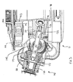
- the present invention also includes the hybrid input quill utilized in a concentric face gear transmission assembly 111.
- the transmission assembly 111 in FIGURE 3 includes the hybrid power quill 170 shown in FIGURE 2.
- the transmission assembly 111 thus includes the hybrid power quill assembly 170, which meshes with the first stage reduction gearing of the transmission.
- Power from an engine or motor is transmitted via clutch 120 to the input shaft 121.
- the input shaft 121 is connected to the input pinion gear 173.
- the input pinion gear 173 is meshed between a lower face gear 125, and an upper face gear 130.
- the lower face gear 125 includes a web 136, which leads to a female spline 138.
- the female spline 138 of the lower face gear 125 meshes with a male spline 141.
- the male spline 141 is connected to a sun gear 143 driving the secondary gearing system of the transmission.
- the sun gear 143 meshes with the inner-radial portion of a planet gear 145.
- the outer-radial portion of the planet gear 145 meshes with a ring gear 149.
- the planet gear is held by a planet carrier 154. Power from the planet carrier 154 may be used to drive the device or vehicle through a drive shaft, or further gearing.
- Not shown in FIGURE 3 are other input quills, which may provide power from other motor(s) or engine(s).
- idler gears which transmit torque between the upper and lower face gears 130 and 125.
- the transmission assembly 111 may have one or more input quills and one or more idler gears.
- two hybrid input quill assemblies 170 are utilized to provide power from two turbine engines, providing auxiliary power output to two sources, while combining the power from the two engines into the main drive system.
- the hybrid input quill assembly 170 shown in FIGURE 3 is the same as the hybrid input quill assembly 170 shown in FIGURE 2.
- the position of the input shaft 121 and the shaft pinion gear 173 may be adjusted through the shaft pinion shim(s) 177.
- Attached to the input shaft 121 is the bevel pinion gear 175, forming the hybrid input quill 170.
- the location of the bevel pinion gear 175 may be adjusted by varying the thickness of the bevel pinions shim(s) 179.
- the bevel pinion gear 175 meshes with the bevel power takeoff gear 190.
- the bevel power takeoff gear is connected directly to the auxiliary power devices (not shown) designed to be driven by the auxiliary power takeoff from this transmission.
- the bevel power takeoff gear 190 is suitably connected indirectly to the auxiliary power devices (not shown) via additional clutches or gearing (not shown).
- one or more of the auxiliary systems is a rear rotor for a rotorcraft.
- the bevel pinion shim(s) 179 and the shaft pinion shim(s) 177 allow the location of the bevel pinion gear 175 to be adjusted to properly mesh with the bevel power takeoff gear 190, while allowing independent adjustment of the location of the shaft pinion gear 173. This permits proper meshing of the shaft pinion gear 173 with the upper face gear 130, and lower face gear 125.
- two hybrid input quills 170 are utilized. Both hybrid quills drive the upper and lower face gears 125 and 130, and each drive their own bevel power takeoff gear 190, providing power from two engines or motors (not shown). If one engine or motor becomes inoperative, the other engine or motor, through the opposing face gears 125 and 130, drives the hybrid input quill shaft 121 of the inoperative engine, thus driving the bevel power takeoff gear 175 of the inoperative engine. This provides additional security and safety in a one engine or motor inoperative condition.
- the hybrid input quill 170 may be utilized in a wide variety of transmissions where auxiliary power takeoff is desired while minimizing the size, weight, and complexity of the overall transmission.
- Transmissions may also include standard input quills, without the hybrid input quill system, as well as hybrid input quills with bevel gears.
- the invention is not limited to rotorcraft or aircraft transmissions, but may be utilized in other vehicle or transmission applications where lightweight, simplicity, and size limitations are important. Accordingly, the scope of the invention is not limited by the disclosure of the preferred embodiment. Instead, the invention should be determined entirely by reference to the claims that follow.
Landscapes
- Engineering & Computer Science (AREA)
- Mechanical Engineering (AREA)
- General Engineering & Computer Science (AREA)
- Aviation & Aerospace Engineering (AREA)
- Gear Transmission (AREA)
- Arrangement Of Transmissions (AREA)
- Arrangement And Driving Of Transmission Devices (AREA)
- Paper (AREA)
- Transmissions By Endless Flexible Members (AREA)
Abstract
Description
- This invention relates generally to torque transmission systems, and specifically to lightweight transmission systems for use on rotorcraft, propeller-driven aircraft, and any other mechanically driven vehicle.
- A torque transmission system transfers power from an engine or motor to driven components of a device or vehicle. In a rotorcraft or a propeller-driven aircraft, the proprotor transmission system transfers power from a turbine engine or other engine to the rotor or propeller of the rotorcraft or aircraft. A torque transmission system may direct power from one or more engines to a single driven component or to a number of driven components. The transmission system may also direct power to auxiliary systems. In a rotorcraft, a proprotor transmission system often directs power from two turbine engines to a single rotor, auxiliary systems, and a secondary rotor.
- In many devices and vehicles, the rotational velocity of the driven component or components is significantly lower than the rotational velocity of the output of the driving engines or motors, thus the engine or motor rotational velocity must be reduced by the transmission system. In reducing the rotational velocity of the engine or motor output, torque is increased by the transmission system through a series of intermediate gear stages and shafts before final output to the driven component or components. In rotorcraft or propeller-driven aircraft, large gears are required near the final output of the proprotor transmission system to handle the high torque being supplied to the proprotor(s). A typical main rotor transmission housing these large gears is often the heaviest gear box in a rotorcraft.
- Transmission size, weight, and reliability considerations, are important, especially in aircraft. Prior art transmissions typically power the auxiliary systems directly from the main transmission gears or by adding additional gearing to the main transmission system. This increases size, and adds weight and complexity.
- FIGURE 1 is a full cross-sectional view of a prior art concentric face gear transmission 10 for a rotorcraft. Power from a turbine engine (not shown) is transferred via an
input clutch 20 to aninput shaft 21. Aninput spur pinion 23, connected to theinput shaft 21, is meshed between alower face gear 25 and anupper face gear 30. The combination of theinput shaft 21 and theinput spur pinion 23 will be referred to herein as an input quill. A lower thrust bearing 27 for thelower face gear 25 is located radially inwardly of thelower face gear 25. An upper thrust bearing 32 for theupper face gear 30 is located radially outwardly of theupper face gear 30. Torque from theinput shaft 21 is split between thelower face gear 25 and theupper face gear 30 at a single stage gear meshing 34. - The
upper face gear 30 includes aweb 36, connected to afemale spline 38. Thefemale spline 38 of theupper face gear 30 meshes with amale spline 41. Themale spline 41 is connected to a sun gear 43. The sun gear 43 meshes with an inner radial portion of aplanet gear 45. Theplanet gear 45, having anaxis 47, rotates about the sun gear 43. An outer radial portion of theplanet gear 45 meshes with aring gear 49. Theplanet gears 45 are carried by a planet carrier 54, which rotates around astatic support assembly 56. Power from the planet carrier 54 is used to drive the rotor of the aircraft through a main rotor drive shaft (not shown). - The cross section of FIGURE 1 is taken through an
input spur pinion 23 and anidler pinion 61. In the prior art transmission 10, theinput spur pinion 23 is located opposite a second input spur pinion (not shown) and theidler pinion 61 is located opposite a second idler pinion (not shown). - The
idler pinion 61 is connected to an idler shaft 60, which rotates around an axis that nearly intersects the axis of thestatic support assembly 56. Theidler pinion 61 meshes with thelower face gear 25 and theupper face gear 30 at a singlestage idler mesh 63. The idler pinion transfers and equalizes torque between theupper face gear 30 and thelower face gear 25. - In the prior art concentric face gear transmission 10 shown in FIGURE 1, primary power torque from the first face gear stage of the transmission 10 is output from the
upper face gear 30 through itsweb 36 andfemale spline 38. Auxiliary power is withdrawn from the transmission through the idler shaft 60, which is driven by theupper face gear 30 andlower face gear 25. Theupper face gear 30 and thelower face gear 25 must carry the torque driving the auxiliary system together with the main power torque, necessitating heavier face gears. Also, the extraction of auxiliary power through the use of anidler pinion 61 and idler shaft 60 requires that the transmission housing and configuration be sized to accommodate larger idler components when they are utilized to drive auxiliary systems. - More generally, many forms of transmissions are often driven by input pinion or bevel gears on shafts, i.e. input quills, with auxiliary power extracted through additional gear components that mesh with the main transmission gears. For example, other prior art transmissions utilize input quills linked to bevel gears to drive secondary gearing in the transmission, without utilizing a face gear configuration. Alternately other prior art utilizes input pinion gears with single face gears, not utilizing concentric torque face gears. Examples of such transmissions are shown in FIGURES 1 and 2 of U.S. Patent No. 5,802,918, Chen et al., September 8, 1998. Independent of the configuration of the transmission, auxiliary power takeoffs for prior art transmissions as described herein, and other prior art, utilize the main power transmission system to drive the auxiliary power system, increasing its weight, and requiring the space and complexity of additional gearing within the main power system to drive the auxiliary power takeoffs.
- Therefore, an unmet need exists for a transmission system which allows for auxiliary power takeoff without burdening the main transmission system with the weight, size, and complexity of the auxiliary power takeoff.
- The present invention presents a hybrid input quill that presents a lightweight, compact, and uncomplicated system for driving auxiliary power takeoffs while driving a main transmission.
- The hybrid input quill of the present invention includes at least one input pinion and one bevel pinion on a single input shaft allowing for two drive systems to be driven from the single hybrid input quill. The hybrid input quill may be incorporated into a concentric face gear transmission assembly where the input pinion gear drives the main power system of the device or vehicle, and the bevel gear drives auxiliary power systems. The bevel gear drives the auxiliary power system utilizing gearing outside of the primary power train reducing the weight, size, and complexity of the primary power train in the transmission.
- According to an aspect of the invention, power is still transmitted to the auxiliary power system through the hybrid input quill when used in a multiengine configuration and the engine directly driving the hybrid input quill fails or is shut down. A clutch is utilized to disconnect the hybrid input quill from its input motor or engine, allowing the input quill to be driven by the balance of the transmission and other engine(s) or motor(s), providing extra safety or security in the drive system. The then-indirectly powered hybrid quill continues to drive its connected auxiliary system.
- The invention provides flexibility for shimming, spacing, or otherwise locating the gearing systems for the primary power and auxiliary power takeoffs independently, to provide for optimum gear mesh configuration. Thus, the location of the bevel pinion may be shimmed or positioned separate from the input pinion. The input pinion and the bevel pinion may be independently positioned to obtain optimum gear meshing. The location of the input pinion assembly may be shimmed or positioned relative to the main transmission. Shimming of the shaft pinion separate from shimming of the bevel pinion permits both the shaft pinion and the bevel pinion to be located optimally for their respective gearing systems.
- The preferred and alternative embodiments of the present invention are described in detail below with reference to the following drawings.
- FIGURE 1 is a full cross sectional view of a prior art concentric face gear transmission assembly with a standard input quill;
- FIGURE 2 is a cross section view of the hybrid input quill of the instant invention with input shaft, shaft pinion, bevel pinion, and related components; and
- FIGURE 3 is a partial cross sectional view of a concentric face gear transmission assembly incorporating the hybrid input quill, and showing a bevel power takeoff gear meshing with the bevel pinion of the hybrid input quill.
-
- FIGURE 2 is a cross section of a
hybrid input quill 170. Thehybrid input quill 170 includes aninput shaft 121 with an attachedshaft pinion gear 173. Theinput shaft 121 is driven by an engine or motor (not shown) through aninput clutch 120. Theinput shaft 121 is supported by, and allowed to rotate within, themain quill bearings 181. Also attached to theinput shaft 121 is abevel pinion gear 175. In a presently preferred embodiment, thebevel pinion gear 175 is used to drive auxiliary systems, and theshaft pinion gear 173 is used to drive the main transmission (not shown). In this embodiment, thebevel pinion gear 175, and theshaft pinion gear 173, are beveled, permitting thehybrid input quill 170 to be detachably mounted to the main transmission (not shown). - The location of the
shaft pinion gear 173 and thebevel pinion gear 175 can be adjusted as desired through the use of shims or alternative spacing devices. The location of theshaft pinion gear 173 in a presently preferred embodiment shown in FIGURE 2 may be adjusted through the shaft pinion shim(s) 177. Varying the thickness of the shaft pinion shim(s) 177 allows flexible positioning of the input shaft 121 (with the attached pinion gear 173) co-linear with its longitudinal axis, relative to the main transmission (not shown). The location of thebevel pinion gear 175 in a presently preferred embodiment can be adjusted relative to theshaft pinion gear 173 through using different thickness bevel pinion shim(s) 179. The bevel pinion shim(s) 179 are interposed between theinput shaft 121 and thebevel pinion gear 175 permitting flexible, but precise, positioning of the bevel gear along theinput shaft 121. By adjusting the thickness of the shaft pinion shim(s) 177 and the bevel pinion shim(s) 179 in concert, and independently, the location of theshaft pinion gear 173, and thebevel pinion gear 175 can be adjusted independently to obtain optimum gear meshing with their counterparts. - In alternative embodiments, the relative sizes, locations, and the overall configurations of the
shaft pinion gear 173 and thebevel pinion gear 175 may vary considerably. Theinput shaft 121 can be any length as desired for a particular application. Further, suitable alternative coupling and spacing or positioning methods as known in the art can be utilized to connect thebevel pinion gear 175 to theinput shaft 121. Theshaft pinion gear 173 and thebevel pinion gear 175 themselves may also be of different types or configurations as desired for various applications. - As shown in FIGURE 3, the present invention also includes the hybrid input quill utilized in a concentric face gear transmission assembly 111. The transmission assembly 111 in FIGURE 3 includes the
hybrid power quill 170 shown in FIGURE 2. - The transmission assembly 111 thus includes the hybrid
power quill assembly 170, which meshes with the first stage reduction gearing of the transmission. Power from an engine or motor (not shown) is transmitted viaclutch 120 to theinput shaft 121. Theinput shaft 121 is connected to theinput pinion gear 173. Theinput pinion gear 173 is meshed between alower face gear 125, and anupper face gear 130. In the embodiment shown in FIGURE 3, thelower face gear 125 includes aweb 136, which leads to a female spline 138. The female spline 138 of thelower face gear 125 meshes with amale spline 141. Themale spline 141 is connected to a sun gear 143 driving the secondary gearing system of the transmission. The sun gear 143 meshes with the inner-radial portion of aplanet gear 145. The outer-radial portion of theplanet gear 145 meshes with aring gear 149. The planet gear is held by a planet carrier 154. Power from the planet carrier 154 may be used to drive the device or vehicle through a drive shaft, or further gearing. Not shown in FIGURE 3 are other input quills, which may provide power from other motor(s) or engine(s). Also not shown in FIGURE 3 are idler gears, which transmit torque between the upper and lower face gears 130 and 125. The transmission assembly 111 may have one or more input quills and one or more idler gears. In a presently preferred embodiment, two hybridinput quill assemblies 170 are utilized to provide power from two turbine engines, providing auxiliary power output to two sources, while combining the power from the two engines into the main drive system. - The hybrid
input quill assembly 170 shown in FIGURE 3 is the same as the hybridinput quill assembly 170 shown in FIGURE 2. The position of theinput shaft 121 and theshaft pinion gear 173 may be adjusted through the shaft pinion shim(s) 177. Attached to theinput shaft 121 is thebevel pinion gear 175, forming thehybrid input quill 170. The location of thebevel pinion gear 175 may be adjusted by varying the thickness of the bevel pinions shim(s) 179. Thebevel pinion gear 175 meshes with the bevelpower takeoff gear 190. The bevel power takeoff gear is connected directly to the auxiliary power devices (not shown) designed to be driven by the auxiliary power takeoff from this transmission. Alternatively, the bevelpower takeoff gear 190 is suitably connected indirectly to the auxiliary power devices (not shown) via additional clutches or gearing (not shown). In a presently preferred embodiment, one or more of the auxiliary systems is a rear rotor for a rotorcraft. The bevel pinion shim(s) 179 and the shaft pinion shim(s) 177 allow the location of thebevel pinion gear 175 to be adjusted to properly mesh with the bevelpower takeoff gear 190, while allowing independent adjustment of the location of theshaft pinion gear 173. This permits proper meshing of theshaft pinion gear 173 with theupper face gear 130, andlower face gear 125. - In a presently preferred embodiment, two hybrid input quills 170 are utilized. Both hybrid quills drive the upper and lower face gears 125 and 130, and each drive their own bevel
power takeoff gear 190, providing power from two engines or motors (not shown). If one engine or motor becomes inoperative, the other engine or motor, through the opposing face gears 125 and 130, drives the hybridinput quill shaft 121 of the inoperative engine, thus driving the bevelpower takeoff gear 175 of the inoperative engine. This provides additional security and safety in a one engine or motor inoperative condition. - In alternative embodiments, the
hybrid input quill 170 may be utilized in a wide variety of transmissions where auxiliary power takeoff is desired while minimizing the size, weight, and complexity of the overall transmission. - While the preferred embodiment of the invention has been illustrated and described, as noted above, many changes can be made without departing from the spirit and scope of the invention. For example, alternative spacing or attachment methods may be utilized for positioning the
bevel gear 175 and thepinion gear 173 independently within thehybrid input quill 170. Such devices include set or adjustment screws, or threaded couplings with locking provisions. Alternative gear configurations may be used, including conventional bevel gears mating with conventional bevel gears or conventional straight gears used in place of the input pinion gear end or the bevel pinion gear. Further, more than two gears may be attached to a single input shaft. In other embodiments, the primary power may be extracted from the bevel gear, while the pinion gear provides auxiliary power. Transmissions may also include standard input quills, without the hybrid input quill system, as well as hybrid input quills with bevel gears. The invention is not limited to rotorcraft or aircraft transmissions, but may be utilized in other vehicle or transmission applications where lightweight, simplicity, and size limitations are important. Accordingly, the scope of the invention is not limited by the disclosure of the preferred embodiment. Instead, the invention should be determined entirely by reference to the claims that follow.
Claims (21)
- A hybrid quill for providing auxiliary power and main power to a transmission, comprising:a hybrid input shaft, having a longitudinal axis and a circumference, and an input end and a distal end;an input pinion gear attached about the circumference of the hybrid input shaft and arranged for meshing with a main drive adapted for driving a device or a vehicle;at least one bevel pinion gear attached about the circumference of the hybrid input shaft and arranged for meshing with an auxiliary drive adapted for driving an auxiliary system of the device or vehicle; andthe at least one bevel pinion gear being laterally spaced apart from the input pinion gear along the longitudinal axis of the hybrid input shaft.
- The hybrid input quill of Claim 1, wherein:the input pinion gear is attached about the circumference of the hybrid input shaft at the distal end of the hybrid input shaft; andthe at least one bevel pinion gear is attached about the circumference of the hybrid input shaft at the input end of the hybrid input shaft.
- The hybrid input quill of Claim 1, wherein:the input pinion gear is arranged for detachably meshing with the main drive; andthe at least one bevel pinion gear is arranged for detachably meshing with the auxiliary drive.
- The hybrid input quill of Claim 1, further comprising:at least one input pinion gear spacing device, rotatably attached to the hybrid input shaft, and interposed between the hybrid input shaft and the main drive, arranged for adjusting the position of the hybrid input shaft and the input pinion gear relative to the main drive, co-linear with the longitudinal axis of the hybrid input shaft.
- The hybrid input quill of Claim 1, further comprising:at least one bevel pinion gear spacing device, interposed between the hybrid input shaft and the bevel pinion gear, arranged for adjusting the position of the bevel pinion gear relative to the hybrid input shaft, along the longitudinal axis of the hybrid input shaft.
- The hybrid input quill of Claim 2, further comprising:at least one bevel pinion gear spacing device, interposed between the hybrid input shaft and the bevel pinion gear, arranged for positioning the bevel pinion gear relative to the hybrid input shaft, along the longitudinal axis of the hybrid input shaft.
- A gear positioning system for a hybrid input quill for providing auxiliary power and main power to a transmission, comprising:a hybrid input shaft, having a circumference, rotatably supported by at least one bearing;an input pinion gear attached about the circumference of the hybrid input shaft;an input quill spacing device attached to the at least one bearing, interposed between the at least one bearing and a transmission assembly;a bevel pinion gear spacing device, attached to the hybrid input shaft; anda bevel pinion gear attached to the bevel pinion gear spacing device and attached about the circumference of the hybrid input shaft.
- The gear positioning system of Claim 7, wherein:the input quill spacing device comprises at least one shim.
- The gear positioning system of Claim 7, wherein:the bevel pinion gear spacing device comprises at least one shim.
- A transmission with a hybrid input quill, comprising:a hybrid input shaft, having a longitudinal axis and a circumference;an input gear, having a plurality of input teeth, attached about the circumference of the hybrid input shaft;a driving gear, adapted for driving a device or a vehicle, having a plurality of driven gear teeth, contacting the input teeth;at least one auxiliary input gear, having a plurality of auxiliary input teeth, attached about the circumference of the hybrid input shaft;at least one auxiliary driven gear, not connected to the driving gear, adapted for driving an auxiliary system of the device or vehicle, having a plurality of auxiliary driven teeth, contacting the auxiliary input teeth.
- The transmission of Claim 10, wherein the driving gear is a face gear.
- The transmission of Claim 10, wherein:the input teeth are arranged for detachably contacting with the driven gear teeth; andthe auxiliary input teeth are arranged for detachably contacting with the auxiliary driven teeth.
- The transmission of Claim 10, further comprising:at least one input quill spacing device, rotatably attached to the hybrid input shaft, and interposed between the hybrid input shaft and the driving gear, arranged for adjusting the position of the hybrid input shaft and the input gear relative to the driving gear, co-linear with the longitudinal axis of the hybrid input shaft.at least one auxiliary gear spacing device, interposed between the hybrid input shaft and the auxiliary input gear, arranged for positioning the auxiliary input gear relative to the hybrid input shaft, along the longitudinal axis of the hybrid input shaft.
- The transmission of Claim 13, wherein:the input quill spacing device comprises at least one shim.
- The transmission of Claim 13, wherein:the bevel pinion gear spacing device comprises at least one shim.
- A face gear transmission with a hybrid input quill, comprising:a hybrid input shaft having a longitudinal axis and a circumference;an input pinion gear, having a plurality of input pinion teeth, attached about the circumference of the hybrid input shaft;a face gear, adapted for driving a device or a vehicle, having a plurality of face gear teeth, contacting the input pinion teeth;at least one bevel pinion gear, having a plurality of bevel pinion teeth, attached about the circumference of the hybrid input shaft;at least one bevel auxiliary gear, adapted for driving an auxiliary system of the device or vehicle, having a plurality of bevel auxiliary teeth, contacting the bevel pinion teeth.
- The transmission of Claim 16, further comprising:a second hybrid input shaft, having a circumference;a second input pinion gear, having a plurality of second input pinion teeth, attached about the circumference of the second hybrid input shaft, contacting the face gear teeth;at least one second bevel pinion gear, having a plurality of second bevel pinion teeth, attached about the circumference of the second hybrid input shaft;at least one bevel auxiliary gear, adapted for driving a second auxiliary system of the device or vehicle, having a plurality of second bevel auxiliary teeth, contacting the second bevel pinion teeth.
- The transmission of Claim 16, wherein:the input pinion teeth are arranged for detachably contacting with the face gear teeth; andthe bevel pinion teeth are arranged for detachably contacting with the bevel auxiliary teeth.
- The transmission of Claim 16, further comprising:at least one input pinion quill spacing device, rotatably attached to the hybrid input shaft arranged for adjusting the position of the hybrid input shaft and the input pinion gear relative to the face gear, co-linear to the longitudinal axis of the hybrid input shaft; andat least one bevel pinion gear spacing device, attached to the hybrid input shaft and connected to the bevel pinion gear arranged for positioning the bevel pinion gear relative to the hybrid input shaft, along the longitudinal axis of the hybrid input shaft.
- The gear positioning system of Claim 19, wherein:the input quill spacing device comprises at least one shim.
- The gear positioning system of Claim 19, wherein:the bevel pinion gear spacing device comprises at least one shim.
Applications Claiming Priority (2)
| Application Number | Priority Date | Filing Date | Title |
|---|---|---|---|
| US09/961,117 US6443035B1 (en) | 2001-09-20 | 2001-09-20 | Hybrid power input quill for transmissions |
| US961117 | 2001-09-20 |
Publications (3)
| Publication Number | Publication Date |
|---|---|
| EP1295788A2 true EP1295788A2 (en) | 2003-03-26 |
| EP1295788A3 EP1295788A3 (en) | 2005-08-03 |
| EP1295788B1 EP1295788B1 (en) | 2008-12-10 |
Family
ID=25504083
Family Applications (1)
| Application Number | Title | Priority Date | Filing Date |
|---|---|---|---|
| EP02078142A Expired - Lifetime EP1295788B1 (en) | 2001-09-20 | 2002-07-31 | Hybrid power input quill for transmissions |
Country Status (6)
| Country | Link |
|---|---|
| US (1) | US6443035B1 (en) |
| EP (1) | EP1295788B1 (en) |
| JP (1) | JP2003175898A (en) |
| AT (1) | ATE416972T1 (en) |
| DE (1) | DE60230219D1 (en) |
| ES (1) | ES2316519T3 (en) |
Families Citing this family (10)
| Publication number | Priority date | Publication date | Assignee | Title |
|---|---|---|---|---|
| FR2871138B1 (en) * | 2004-06-07 | 2006-08-04 | Eurocopter France | TRANSMISSION MECHANISM BETWEEN ACCESSORIES AND ROTOR DRIVE ENGINE ORGANS OF A ROTOR, SELECTIVELY ISOLATED OR JOINTLY |
| US8779609B2 (en) * | 2010-06-15 | 2014-07-15 | Hamilton Sundstrand Corporation | Time delay contactor for aircraft APU starter |
| US8222848B2 (en) * | 2010-06-15 | 2012-07-17 | Hamilton Sundstrand Corporation | Time delay contactor for aircraft APU starter |
| EP2610525B1 (en) * | 2011-12-30 | 2017-09-06 | LEONARDO S.p.A. | Epicyclic gear train for a hovering aircraft having annularly arranged lubricant nozzles |
| US9097186B2 (en) | 2012-01-29 | 2015-08-04 | United Technologies Corporation | Bevel gear arrangement for axial accessory gearbox |
| CN103921948B (en) * | 2014-03-28 | 2015-10-21 | 吉林大学 | Hybrid twin-engine coaxial twin-screw helicopter |
| US10385959B2 (en) * | 2016-02-16 | 2019-08-20 | Bell Helicopter Textron Inc. | Flange-mounted ring gear for improved heat management |
| US10221939B2 (en) * | 2016-02-16 | 2019-03-05 | Bell Helicopter Textron Inc. | System and apparatus for supporting a planetary carrier within a gearbox |
| CN105650206A (en) * | 2016-03-31 | 2016-06-08 | 中国航空动力机械研究所 | Helicopter transmission device |
| US11794913B2 (en) | 2020-10-20 | 2023-10-24 | The Boeing Company | Integrated electric propulsion unit |
Citations (1)
| Publication number | Priority date | Publication date | Assignee | Title |
|---|---|---|---|---|
| US5802918A (en) | 1996-10-16 | 1998-09-08 | Mcdonnell Douglas Helicopter Co. | Concentric face gear transmission assembly |
Family Cites Families (10)
| Publication number | Priority date | Publication date | Assignee | Title |
|---|---|---|---|---|
| US2811324A (en) * | 1953-10-27 | 1957-10-29 | United Aircraft Corp | Turbo-jet driven helicopter |
| GB767426A (en) * | 1953-11-09 | 1957-02-06 | Napier & Son Ltd | Transmission mechanism including bevel pinions |
| US3129608A (en) * | 1959-12-04 | 1964-04-21 | Westland Aircraft Ltd | Mechanical gearing |
| GB1389403A (en) * | 1971-06-01 | 1975-04-03 | Westland Aircraft Ltd | Helicopter power transmission systems |
| NL8503488A (en) * | 1985-12-18 | 1987-07-16 | Daf Special Products B V | GEAR TRANSMISSION, ESPECIALLY FOR HELICOPTER APPLICATION. |
| US5149311A (en) | 1985-12-18 | 1992-09-22 | Daf Special Products | Gear unit, particularly for use in a helicopter |
| US5182960A (en) | 1991-12-10 | 1993-02-02 | Allied-Signal Inc. | Bevel gear drive arrangement |
| US5233886A (en) | 1992-05-26 | 1993-08-10 | Lucas Western, Inc. | Increased capacity face gear arrangement for transmitting torque through an angle and to a plurality of power extraction paths |
| US5472386A (en) * | 1994-05-26 | 1995-12-05 | United Technologies Corporation | Stacked compound planetary gear train for an upgraded powertrain system for a helicopter |
| US6058791A (en) * | 1998-03-19 | 2000-05-09 | Alliedsignal, Inc. | Accessory mechanical drive for a gas turbine engine |
-
2001
- 2001-09-20 US US09/961,117 patent/US6443035B1/en not_active Expired - Lifetime
-
2002
- 2002-07-31 ES ES02078142T patent/ES2316519T3/en not_active Expired - Lifetime
- 2002-07-31 AT AT02078142T patent/ATE416972T1/en not_active IP Right Cessation
- 2002-07-31 EP EP02078142A patent/EP1295788B1/en not_active Expired - Lifetime
- 2002-07-31 DE DE60230219T patent/DE60230219D1/en not_active Expired - Lifetime
- 2002-09-19 JP JP2002272749A patent/JP2003175898A/en active Pending
Patent Citations (1)
| Publication number | Priority date | Publication date | Assignee | Title |
|---|---|---|---|---|
| US5802918A (en) | 1996-10-16 | 1998-09-08 | Mcdonnell Douglas Helicopter Co. | Concentric face gear transmission assembly |
Also Published As
| Publication number | Publication date |
|---|---|
| ATE416972T1 (en) | 2008-12-15 |
| DE60230219D1 (en) | 2009-01-22 |
| EP1295788A3 (en) | 2005-08-03 |
| ES2316519T3 (en) | 2009-04-16 |
| US6443035B1 (en) | 2002-09-03 |
| JP2003175898A (en) | 2003-06-24 |
| EP1295788B1 (en) | 2008-12-10 |
Similar Documents
| Publication | Publication Date | Title |
|---|---|---|
| US12000344B2 (en) | Aircraft turbine engine with an off-axis propeller | |
| EP3859134B1 (en) | Multi-engine aircraft and method of operating a multi-engine aircraft | |
| US6302356B1 (en) | Helicopter two stage main reduction gearbox | |
| US5802918A (en) | Concentric face gear transmission assembly | |
| US8015900B2 (en) | Split-torque gear box | |
| US4118997A (en) | Bevel gearing | |
| US7918146B2 (en) | Multi-path rotary wing aircraft gearbox | |
| US5823470A (en) | Split torque proprotor transmission | |
| JPS61247595A (en) | Main speed change gear box for twin engine helicopter | |
| US8870538B2 (en) | Counter rotating facegear gearbox | |
| US6443035B1 (en) | Hybrid power input quill for transmissions | |
| EP0234058B1 (en) | Gear unit, particularly for use in a helicopter | |
| White | Design study of a split-torque helicopter transmission | |
| US20260071574A1 (en) | Reduction gearbox for gas turbine engine | |
| US12163477B2 (en) | Turbomachine comprising a speed reduction gear and at least one electric machine | |
| EP3617550A1 (en) | Transmission for engine with two power inputs | |
| US10724625B2 (en) | Torsionally compliant geartrain carrier assembly | |
| US20040214682A1 (en) | Dual stage differential speed transmission | |
| EP3299288B1 (en) | High speed engine reduction gearboxes | |
| US12448120B2 (en) | Shaft assembly for split torque gear box | |
| EP4461992A1 (en) | Method and system for assembling a reduction gearbox | |
| EP4567302A1 (en) | Epicyclic system with bevel attachment for dual-power applications | |
| GB2151329A (en) | Marine propulsion gearbox |
Legal Events
| Date | Code | Title | Description |
|---|---|---|---|
| PUAI | Public reference made under article 153(3) epc to a published international application that has entered the european phase |
Free format text: ORIGINAL CODE: 0009012 |
|
| AK | Designated contracting states |
Kind code of ref document: A2 Designated state(s): AT BE BG CH CY CZ DE DK EE ES FI FR GB GR IE IT LI LU MC NL PT SE SK TR Designated state(s): AT BE BG CH CY CZ DE DK EE ES FI FR GB GR IE IT LI LU MC NL PT SE SK TR |
|
| AX | Request for extension of the european patent |
Extension state: AL LT LV MK RO SI |
|
| PUAL | Search report despatched |
Free format text: ORIGINAL CODE: 0009013 |
|
| AK | Designated contracting states |
Kind code of ref document: A3 Designated state(s): AT BE BG CH CY CZ DE DK EE ES FI FR GB GR IE IT LI LU MC NL PT SE SK TR |
|
| AX | Request for extension of the european patent |
Extension state: AL LT LV MK RO SI |
|
| RIC1 | Information provided on ipc code assigned before grant |
Ipc: 7B 64C 27/14 A Ipc: 7F 16H 37/06 B Ipc: 7F 16H 1/14 B Ipc: 7B 60K 17/28 B Ipc: 7F 16H 1/22 B Ipc: 7B 64D 35/00 B |
|
| 17P | Request for examination filed |
Effective date: 20050902 |
|
| AKX | Designation fees paid |
Designated state(s): AT BE BG CH CY CZ DE DK EE ES FI FR GB GR IE IT LI LU MC NL PT SE SK TR |
|
| GRAP | Despatch of communication of intention to grant a patent |
Free format text: ORIGINAL CODE: EPIDOSNIGR1 |
|
| GRAS | Grant fee paid |
Free format text: ORIGINAL CODE: EPIDOSNIGR3 |
|
| RAP1 | Party data changed (applicant data changed or rights of an application transferred) |
Owner name: THE BOEING COMPANY |
|
| GRAA | (expected) grant |
Free format text: ORIGINAL CODE: 0009210 |
|
| AK | Designated contracting states |
Kind code of ref document: B1 Designated state(s): AT BE BG CH CY CZ DE DK EE ES FI FR GB GR IE IT LI LU MC NL PT SE SK TR |
|
| REG | Reference to a national code |
Ref country code: GB Ref legal event code: FG4D |
|
| REG | Reference to a national code |
Ref country code: CH Ref legal event code: EP |
|
| REG | Reference to a national code |
Ref country code: IE Ref legal event code: FG4D |
|
| REF | Corresponds to: |
Ref document number: 60230219 Country of ref document: DE Date of ref document: 20090122 Kind code of ref document: P |
|
| REG | Reference to a national code |
Ref country code: ES Ref legal event code: FG2A Ref document number: 2316519 Country of ref document: ES Kind code of ref document: T3 |
|
| PG25 | Lapsed in a contracting state [announced via postgrant information from national office to epo] |
Ref country code: NL Free format text: LAPSE BECAUSE OF FAILURE TO SUBMIT A TRANSLATION OF THE DESCRIPTION OR TO PAY THE FEE WITHIN THE PRESCRIBED TIME-LIMIT Effective date: 20081210 Ref country code: FI Free format text: LAPSE BECAUSE OF FAILURE TO SUBMIT A TRANSLATION OF THE DESCRIPTION OR TO PAY THE FEE WITHIN THE PRESCRIBED TIME-LIMIT Effective date: 20081210 |
|
| NLV1 | Nl: lapsed or annulled due to failure to fulfill the requirements of art. 29p and 29m of the patents act | ||
| PG25 | Lapsed in a contracting state [announced via postgrant information from national office to epo] |
Ref country code: BG Free format text: LAPSE BECAUSE OF FAILURE TO SUBMIT A TRANSLATION OF THE DESCRIPTION OR TO PAY THE FEE WITHIN THE PRESCRIBED TIME-LIMIT Effective date: 20090310 Ref country code: EE Free format text: LAPSE BECAUSE OF FAILURE TO SUBMIT A TRANSLATION OF THE DESCRIPTION OR TO PAY THE FEE WITHIN THE PRESCRIBED TIME-LIMIT Effective date: 20081210 Ref country code: BE Free format text: LAPSE BECAUSE OF FAILURE TO SUBMIT A TRANSLATION OF THE DESCRIPTION OR TO PAY THE FEE WITHIN THE PRESCRIBED TIME-LIMIT Effective date: 20081210 |
|
| PG25 | Lapsed in a contracting state [announced via postgrant information from national office to epo] |
Ref country code: CZ Free format text: LAPSE BECAUSE OF FAILURE TO SUBMIT A TRANSLATION OF THE DESCRIPTION OR TO PAY THE FEE WITHIN THE PRESCRIBED TIME-LIMIT Effective date: 20081210 Ref country code: SE Free format text: LAPSE BECAUSE OF FAILURE TO SUBMIT A TRANSLATION OF THE DESCRIPTION OR TO PAY THE FEE WITHIN THE PRESCRIBED TIME-LIMIT Effective date: 20090310 Ref country code: PT Free format text: LAPSE BECAUSE OF FAILURE TO SUBMIT A TRANSLATION OF THE DESCRIPTION OR TO PAY THE FEE WITHIN THE PRESCRIBED TIME-LIMIT Effective date: 20090511 Ref country code: AT Free format text: LAPSE BECAUSE OF FAILURE TO SUBMIT A TRANSLATION OF THE DESCRIPTION OR TO PAY THE FEE WITHIN THE PRESCRIBED TIME-LIMIT Effective date: 20081210 |
|
| PG25 | Lapsed in a contracting state [announced via postgrant information from national office to epo] |
Ref country code: SK Free format text: LAPSE BECAUSE OF FAILURE TO SUBMIT A TRANSLATION OF THE DESCRIPTION OR TO PAY THE FEE WITHIN THE PRESCRIBED TIME-LIMIT Effective date: 20081210 |
|
| PLBE | No opposition filed within time limit |
Free format text: ORIGINAL CODE: 0009261 |
|
| STAA | Information on the status of an ep patent application or granted ep patent |
Free format text: STATUS: NO OPPOSITION FILED WITHIN TIME LIMIT |
|
| PG25 | Lapsed in a contracting state [announced via postgrant information from national office to epo] |
Ref country code: DK Free format text: LAPSE BECAUSE OF FAILURE TO SUBMIT A TRANSLATION OF THE DESCRIPTION OR TO PAY THE FEE WITHIN THE PRESCRIBED TIME-LIMIT Effective date: 20081210 |
|
| 26N | No opposition filed |
Effective date: 20090911 |
|
| PG25 | Lapsed in a contracting state [announced via postgrant information from national office to epo] |
Ref country code: MC Free format text: LAPSE BECAUSE OF NON-PAYMENT OF DUE FEES Effective date: 20090731 |
|
| REG | Reference to a national code |
Ref country code: CH Ref legal event code: PL |
|
| REG | Reference to a national code |
Ref country code: IE Ref legal event code: MM4A |
|
| PG25 | Lapsed in a contracting state [announced via postgrant information from national office to epo] |
Ref country code: CH Free format text: LAPSE BECAUSE OF NON-PAYMENT OF DUE FEES Effective date: 20090731 Ref country code: LI Free format text: LAPSE BECAUSE OF NON-PAYMENT OF DUE FEES Effective date: 20090731 |
|
| PG25 | Lapsed in a contracting state [announced via postgrant information from national office to epo] |
Ref country code: IE Free format text: LAPSE BECAUSE OF NON-PAYMENT OF DUE FEES Effective date: 20090731 |
|
| PG25 | Lapsed in a contracting state [announced via postgrant information from national office to epo] |
Ref country code: GR Free format text: LAPSE BECAUSE OF FAILURE TO SUBMIT A TRANSLATION OF THE DESCRIPTION OR TO PAY THE FEE WITHIN THE PRESCRIBED TIME-LIMIT Effective date: 20090311 |
|
| PG25 | Lapsed in a contracting state [announced via postgrant information from national office to epo] |
Ref country code: LU Free format text: LAPSE BECAUSE OF NON-PAYMENT OF DUE FEES Effective date: 20090731 |
|
| PG25 | Lapsed in a contracting state [announced via postgrant information from national office to epo] |
Ref country code: TR Free format text: LAPSE BECAUSE OF FAILURE TO SUBMIT A TRANSLATION OF THE DESCRIPTION OR TO PAY THE FEE WITHIN THE PRESCRIBED TIME-LIMIT Effective date: 20081210 |
|
| PG25 | Lapsed in a contracting state [announced via postgrant information from national office to epo] |
Ref country code: CY Free format text: LAPSE BECAUSE OF FAILURE TO SUBMIT A TRANSLATION OF THE DESCRIPTION OR TO PAY THE FEE WITHIN THE PRESCRIBED TIME-LIMIT Effective date: 20081210 |
|
| REG | Reference to a national code |
Ref country code: FR Ref legal event code: PLFP Year of fee payment: 15 |
|
| REG | Reference to a national code |
Ref country code: FR Ref legal event code: PLFP Year of fee payment: 16 |
|
| REG | Reference to a national code |
Ref country code: FR Ref legal event code: PLFP Year of fee payment: 17 |
|
| PGFP | Annual fee paid to national office [announced via postgrant information from national office to epo] |
Ref country code: ES Payment date: 20200803 Year of fee payment: 19 Ref country code: DE Payment date: 20200729 Year of fee payment: 19 Ref country code: GB Payment date: 20200727 Year of fee payment: 19 Ref country code: FR Payment date: 20200727 Year of fee payment: 19 |
|
| PGFP | Annual fee paid to national office [announced via postgrant information from national office to epo] |
Ref country code: IT Payment date: 20200724 Year of fee payment: 19 |
|
| REG | Reference to a national code |
Ref country code: DE Ref legal event code: R119 Ref document number: 60230219 Country of ref document: DE |
|
| GBPC | Gb: european patent ceased through non-payment of renewal fee |
Effective date: 20210731 |
|
| PG25 | Lapsed in a contracting state [announced via postgrant information from national office to epo] |
Ref country code: GB Free format text: LAPSE BECAUSE OF NON-PAYMENT OF DUE FEES Effective date: 20210731 Ref country code: DE Free format text: LAPSE BECAUSE OF NON-PAYMENT OF DUE FEES Effective date: 20220201 |
|
| PG25 | Lapsed in a contracting state [announced via postgrant information from national office to epo] |
Ref country code: FR Free format text: LAPSE BECAUSE OF NON-PAYMENT OF DUE FEES Effective date: 20210731 |
|
| PG25 | Lapsed in a contracting state [announced via postgrant information from national office to epo] |
Ref country code: IT Free format text: LAPSE BECAUSE OF NON-PAYMENT OF DUE FEES Effective date: 20210731 |
|
| REG | Reference to a national code |
Ref country code: ES Ref legal event code: FD2A Effective date: 20220902 |
|
| PG25 | Lapsed in a contracting state [announced via postgrant information from national office to epo] |
Ref country code: ES Free format text: LAPSE BECAUSE OF NON-PAYMENT OF DUE FEES Effective date: 20210801 |