EP1295014B1 - Transition piece for non-annular gas turbine combustion chambers - Google Patents
Transition piece for non-annular gas turbine combustion chambers Download PDFInfo
- Publication number
- EP1295014B1 EP1295014B1 EP01956465A EP01956465A EP1295014B1 EP 1295014 B1 EP1295014 B1 EP 1295014B1 EP 01956465 A EP01956465 A EP 01956465A EP 01956465 A EP01956465 A EP 01956465A EP 1295014 B1 EP1295014 B1 EP 1295014B1
- Authority
- EP
- European Patent Office
- Prior art keywords
- transition piece
- gas turbine
- combustion chambers
- stage
- axis
- Prior art date
- Legal status (The legal status is an assumption and is not a legal conclusion. Google has not performed a legal analysis and makes no representation as to the accuracy of the status listed.)
- Expired - Lifetime
Links
- 230000007704 transition Effects 0.000 title claims description 52
- 238000002485 combustion reaction Methods 0.000 title claims description 33
- 239000000463 material Substances 0.000 claims description 6
- 229910001347 Stellite Inorganic materials 0.000 claims description 4
- AHICWQREWHDHHF-UHFFFAOYSA-N chromium;cobalt;iron;manganese;methane;molybdenum;nickel;silicon;tungsten Chemical compound C.[Si].[Cr].[Mn].[Fe].[Co].[Ni].[Mo].[W] AHICWQREWHDHHF-UHFFFAOYSA-N 0.000 claims description 4
- 229910001235 nimonic Inorganic materials 0.000 claims description 3
- 239000007789 gas Substances 0.000 description 45
- 239000003344 environmental pollutant Substances 0.000 description 4
- 231100000719 pollutant Toxicity 0.000 description 4
- 239000002184 metal Substances 0.000 description 3
- 229910052751 metal Inorganic materials 0.000 description 3
- 239000000243 solution Substances 0.000 description 3
- PXHVJJICTQNCMI-UHFFFAOYSA-N Nickel Chemical compound [Ni] PXHVJJICTQNCMI-UHFFFAOYSA-N 0.000 description 2
- 238000007689 inspection Methods 0.000 description 2
- 230000010354 integration Effects 0.000 description 2
- 238000011144 upstream manufacturing Methods 0.000 description 2
- 238000007792 addition Methods 0.000 description 1
- 238000003490 calendering Methods 0.000 description 1
- 239000000919 ceramic Substances 0.000 description 1
- 229910017052 cobalt Inorganic materials 0.000 description 1
- 239000010941 cobalt Substances 0.000 description 1
- GUTLYIVDDKVIGB-UHFFFAOYSA-N cobalt atom Chemical compound [Co] GUTLYIVDDKVIGB-UHFFFAOYSA-N 0.000 description 1
- 230000006835 compression Effects 0.000 description 1
- 238000007906 compression Methods 0.000 description 1
- 238000001816 cooling Methods 0.000 description 1
- 230000007797 corrosion Effects 0.000 description 1
- 238000005260 corrosion Methods 0.000 description 1
- 238000010790 dilution Methods 0.000 description 1
- 239000012895 dilution Substances 0.000 description 1
- 230000008030 elimination Effects 0.000 description 1
- 238000003379 elimination reaction Methods 0.000 description 1
- 239000012530 fluid Substances 0.000 description 1
- 239000000446 fuel Substances 0.000 description 1
- 238000003780 insertion Methods 0.000 description 1
- 230000037431 insertion Effects 0.000 description 1
- 238000012423 maintenance Methods 0.000 description 1
- 239000000203 mixture Substances 0.000 description 1
- 229910052759 nickel Inorganic materials 0.000 description 1
- 230000004936 stimulating effect Effects 0.000 description 1
- 230000035882 stress Effects 0.000 description 1
- 229910000601 superalloy Inorganic materials 0.000 description 1
- 230000008646 thermal stress Effects 0.000 description 1
Images


Classifications
-
- F—MECHANICAL ENGINEERING; LIGHTING; HEATING; WEAPONS; BLASTING
- F01—MACHINES OR ENGINES IN GENERAL; ENGINE PLANTS IN GENERAL; STEAM ENGINES
- F01D—NON-POSITIVE DISPLACEMENT MACHINES OR ENGINES, e.g. STEAM TURBINES
- F01D9/00—Stators
- F01D9/02—Nozzles; Nozzle boxes; Stator blades; Guide conduits, e.g. individual nozzles
- F01D9/023—Transition ducts between combustor cans and first stage of the turbine in gas-turbine engines; their cooling or sealings
Definitions
- the present invention relates to a transition piece for non-annular gas turbine combustion chambers.
- gas turbines comprise a compressor, to which air from the external environment is supplied in order to pressurise the compressor.
- the compressed air passes into a series of combustion chambers which end in a nozzle, into each of which an injector supplies fuel, which is mixed with the air in order to form a mixture of combustible air to be burnt.
- the burnt gases are conveyed towards the turbine, which transforms the enthalpy of the burnt gases in the said combustion chamber into mechanical energy which is available to a user.
- transition pieces in a gas turbine are substantially tubular elements, each of which is used to connect a combustion chamber, which belongs to the combustion system of the gas turbine, to the first stage of the said gas turbine.
- combustion chambers comprise a plurality of elements with a generally cylindrical shape, which are provided with nozzles disposed around an annular development.
- transition pieces are disposed with an annular development, in order to direct the flow of hot burnt gases from the combustion chambers to the first stage of the gas turbine.
- the transition pieces have an upstream aperture for the flow of gas, which is generally cylindrical, and is used to receive the flow of gas directly from the corresponding combustion chamber, and are configured in a longitudinal direction such that their downstream ends comprise arcuate segments which open towards the first stage of the gas turbine.
- transition pieces can direct the flow of gas with a high level of enthalpy obtained from spaced, generally cylindrical flow configurations, towards arcuate segments which form a ring-type configuration relative to the first stage of the gas turbine.
- the document EP-A-753 704 discloses a transition piece having a mount connector device and a body with a lead in axis parallel to the gas turbine axes.
- these components comprise the combustion chamber, the nozzles and the transition pieces, and are the ones which are subjected to the highest temperatures.
- the combustion system since the combustion system has an energising function in relation to the thermal carrier fluid, it is the true heart of the turbine engine, and thus defines its level of emission, and, according to the service life of its own components, also defines the intervals of functioning between machine stoppages, which are necessary in order to carry out inspections of the combustion chambers.
- a major technical problem therefore consists substantially of determining solutions which permit achievement of maximum satisfaction of the client for the three aforementioned aspects, all by means of innovative creations which are economically acceptable.
- stellite 6 deposited onto elements which may become worn by relative vibratory motion, and of super-alloys with a nickel/cobalt base, with high levels of mechanical characteristics and of resistance to corrosion at high temperatures.
- the original system having six combustion chambers, arranged in two rows of three parallel chambers stacked on both sides of the machine, in an arrangement at right-angles to the machine axis, with interposition of 90° connection elbows between the liners and transition pieces, has thus been replaced by an arrangement characterised by chambers inclined by only a few degrees in relation to the machine axis, and insertion of the liners directly in the transition piece, and therefore without the need for further connection elements.
- the object of the present invention is therefore to provide a transition piece for non-annular gas turbine combustion chambers, which permits optimisation of the performance in operation.
- a further object of the invention is to provide a transition piece for non-annular gas turbine combustion chambers, which permits improved efficiency in operation.
- Another object of the invention is to provide a transition piece for non-annular gas turbine combustion chambers, which permits a longer service life of the machine.
- a further object of the invention is to provide a transition piece for a non-annular gas turbine combustion chamber system, which generates fewer pollutant emissions.
- a transition piece for non-annular gas turbine combustion chambers comprising a body which has a cylindrical section, relative to a first terminal end, which ends with an aperture for connection to a combustion chamber, and a second terminal end, which is connected to the first stage of a gas turbine, having a projecting connection arm, for support on the turbine stator, wherein the said projecting connection arm makes it possible to obtain a lead-in axis with an angle of between 5° and 7° relative to an axis, which is parallel to the axis of the machine, and is perpendicular to the plane on which there lies the frame for interfacing of the transition piece with the ring of nozzles which belong to the first stage of the said gas turbine.
- the transition piece has a support arm, with a circular or elliptical base, which is present at the said second terminal end, and surrounds the flow aperture of the said transition piece, wherein the said support arm with a circular or elliptical base has an upper side and a lower side, for its own connection to the first stage of the said gas turbine.
- the cylindrical section relative to the first terminal end, has an anti-wear deposit made of Stellite 6 or another, similar material.
- a deposit of the TBC type is provided on the entire inner surface of the said transition piece, in order to reduce the temperature of the metal.
- the distance between the centre of the lead-in of the said transition piece and the support plane of the flange for anchorage to the stator of the said gas turbine is between 350 mm and 380 mm.
- the body of the transition piece can be made of Nimonic 263 or of Hastelloy-X.
- transition piece according to the present invention for non-annular gas turbine combustion chambers, is indicated globally by the reference number 10.
- the transition piece 10 consists of a body 11, which receives upstream the flow of burnt gases, directly from the corresponding combustion chamber 25, and is configured longitudinally such as to have a downstream end which opens towards the first stage 17 of the gas turbine 18.
- the body 11 of the transition piece 10 has a cylindrical section 13, relative to a first terminal end, which ends with an aperture 14 for connection to a combustion chamber 25.
- the body 11 of the transition piece 10 also has a second terminal end 16, which is connected to the first stage 17 of a gas turbine 18, and thus has a flow aperture 15.
- the transition piece 10 thus consists of a body 11, which is provided with a support arm, with a circular or elliptical base, which is present at the second terminal end 16, and surrounds the flow aperture 15.
- the support arm with a circular or elliptical base has an upper side 20 and a lower side 21.
- the body 11 is provided with characteristics of resilience, such as to minimise the stresses associated with its anchorage onto the stator of the said gas turbine 18.
- the body 11 is preferably made of Nimonic 263, or, alternatively, of Hastelloy-X, and is produced in a single component part, indicated by the reference number 11, which reduces the parts necessary and the assembly time, and thus permits considerable savings.
- the cylindrical section 13, relative to the first terminal end, has an anti-wear deposit made of Stellite 6, or of another material homologous with that used on the Hula Seals of the liners.
- a deposit of the TBC type is provided on the entire inner surface of the body 11 of the transition piece 10, in order to reduce the temperature of the metal.
- the transition piece 11 also has a projecting connection arm, indicated as a whole by the reference number 22, for support on the turbine stator.
- the projecting connection arm 22 also has a hole 30, for its own connection to the first stage of the gas turbine 18, and a centring pin 31.
- the geometry of the transition piece 11 is thus completely re-shaped, compared with the known art.
- the distance between the centre of the lead-in of the transition piece 10 and the support plane of the flange for anchorage to the stator of the gas turbine is between 350 mm and 380 mm.
- the most significant functioning parameters are: Tmax of the gas ⁇ 1300°C, and Pmax of the gas ⁇ 10 Ata.
- the transition piece 11 thus formed has an optimal geometric profile, which, inter alia, makes it possible to keep the thermal stresses within acceptable limits.
- transition piece 11 makes it possible to obtain increased structural stability, with consequent reduction of the vibratory motion.
Landscapes
- Engineering & Computer Science (AREA)
- Mechanical Engineering (AREA)
- General Engineering & Computer Science (AREA)
- Turbine Rotor Nozzle Sealing (AREA)
- Gas Burners (AREA)
Description
- figure 1 represents a view, partially in cross-section, of a gas turbine to which there is fitted the transition piece according to the present invention, for non-annular gas turbine combustion chambers;
- figure 2 represents a plan view of a transition piece according to the present invention, for non-annular gas turbine combustion chambers;
- figure 3 represents a view in cross-section according to the plane III-III, of the transition piece in figure 2;
- figure 4 represents a front view of the transition piece in figures 2-3; and
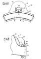
- figure 5 represents a view in cross-section of a detail belonging to the transition piece in figures 2-4.
Claims (5)
- Transition piece (10) for connecting non-annular gas turbine combustion chambers to first stages of a gas turbine, comprising a tubular body (11) which has a cylindrical section (13), relative to a first terminal end, which ends with a first aperture (14) for connection to a combustion chamber (25), and a second terminal end (16), for connection to the first stage (17) of a gas turbine (18), comprising a mount connector device (22) provided on the transition piece (10) and comprising a tubular projection protruding away from the body and curved for securing the transition piece (10) to said first stage (17) of the gas turbine (18), the body (11) having a lead-in axis with an angle of between 5° and 7° relative to an axis which is parallel to the intended axis of the machine, and is perpendicular to the plane on which there lies a frame for interfacing of the said transition piece (10) with the ring of nozzles belonging to the first stage of the said gas turbine (18).
- A transition piece (10) according to claim 1, characterised in that said cylindrical section (13) has an anti-wear deposit, made of Stellite 6 or another similar material at the first aperture (14)
- A transition piece according to claim 1, characterised in that a deposit of the TBC type is provided on the entire inner surface of the said transition piece (10),
- A transition piece according to clam 1, characterised in that said tubular body (11) is made of Nimonic 263 or Hastelloy-X
- A transition piece according to claim 1, characterised in that the distance between the centre of the lead-in of the said transition piece (10) and the support plane of the flange for anchorage to the stator of the said gas turbine (18), is between 350 mm and 380 mm.
Applications Claiming Priority (3)
| Application Number | Priority Date | Filing Date | Title |
|---|---|---|---|
| ITMI001362 | 2000-06-16 | ||
| IT2000MI001362A IT1317978B1 (en) | 2000-06-16 | 2000-06-16 | TRANSITION PIECE FOR COMBUSTION CHAMBERS OF NONANULAR GAS TURBINES. |
| PCT/EP2001/006484 WO2001096712A1 (en) | 2000-06-16 | 2001-06-08 | Transition piece for non-annular gas turbine combustion chambers |
Publications (2)
| Publication Number | Publication Date |
|---|---|
| EP1295014A1 EP1295014A1 (en) | 2003-03-26 |
| EP1295014B1 true EP1295014B1 (en) | 2005-11-23 |
Family
ID=11445283
Family Applications (1)
| Application Number | Title | Priority Date | Filing Date |
|---|---|---|---|
| EP01956465A Expired - Lifetime EP1295014B1 (en) | 2000-06-16 | 2001-06-08 | Transition piece for non-annular gas turbine combustion chambers |
Country Status (12)
| Country | Link |
|---|---|
| US (1) | US20030167776A1 (en) |
| EP (1) | EP1295014B1 (en) |
| AR (1) | AR028133A1 (en) |
| AT (1) | ATE310896T1 (en) |
| AU (1) | AU7844301A (en) |
| BR (1) | BR0111577A (en) |
| DE (1) | DE60115236T2 (en) |
| IT (1) | IT1317978B1 (en) |
| MX (1) | MXPA02012451A (en) |
| NO (1) | NO330416B1 (en) |
| RU (1) | RU2275554C2 (en) |
| WO (1) | WO2001096712A1 (en) |
Families Citing this family (32)
| Publication number | Priority date | Publication date | Assignee | Title |
|---|---|---|---|---|
| US7178341B2 (en) * | 2004-06-17 | 2007-02-20 | Siemens Power Generation, Inc. | Multi-zone tubing assembly for a transition piece of a gas turbine |
| US7278254B2 (en) * | 2005-01-27 | 2007-10-09 | Siemens Power Generation, Inc. | Cooling system for a transition bracket of a transition in a turbine engine |
| US8015818B2 (en) * | 2005-02-22 | 2011-09-13 | Siemens Energy, Inc. | Cooled transition duct for a gas turbine engine |
| US7827801B2 (en) * | 2006-02-09 | 2010-11-09 | Siemens Energy, Inc. | Gas turbine engine transitions comprising closed cooled transition cooling channels |
| US8151570B2 (en) * | 2007-12-06 | 2012-04-10 | Alstom Technology Ltd | Transition duct cooling feed tubes |
| US8113003B2 (en) * | 2008-08-12 | 2012-02-14 | Siemens Energy, Inc. | Transition with a linear flow path for use in a gas turbine engine |
| US8091365B2 (en) * | 2008-08-12 | 2012-01-10 | Siemens Energy, Inc. | Canted outlet for transition in a gas turbine engine |
| US20120186269A1 (en) * | 2011-01-25 | 2012-07-26 | General Electric Company | Support between transition piece and impingement sleeve in combustor |
| RU2597350C2 (en) | 2011-10-24 | 2016-09-10 | Дженерал Электрик Текнолоджи Гмбх | Gas turbine engine, combustion chamber inner shell for gas turbine engine and rotor case for gas turbine engine |
| US9593853B2 (en) * | 2014-02-20 | 2017-03-14 | Siemens Energy, Inc. | Gas flow path for a gas turbine engine |
| EP3341569A1 (en) * | 2015-08-28 | 2018-07-04 | Siemens Aktiengesellschaft | Non-axially symmetric transition ducts for combustors |
| US10830442B2 (en) | 2016-03-25 | 2020-11-10 | General Electric Company | Segmented annular combustion system with dual fuel capability |
| US10584880B2 (en) | 2016-03-25 | 2020-03-10 | General Electric Company | Mounting of integrated combustor nozzles in a segmented annular combustion system |
| US10605459B2 (en) | 2016-03-25 | 2020-03-31 | General Electric Company | Integrated combustor nozzle for a segmented annular combustion system |
| US10584876B2 (en) | 2016-03-25 | 2020-03-10 | General Electric Company | Micro-channel cooling of integrated combustor nozzle of a segmented annular combustion system |
| US11002190B2 (en) | 2016-03-25 | 2021-05-11 | General Electric Company | Segmented annular combustion system |
| US10563869B2 (en) | 2016-03-25 | 2020-02-18 | General Electric Company | Operation and turndown of a segmented annular combustion system |
| US10641491B2 (en) | 2016-03-25 | 2020-05-05 | General Electric Company | Cooling of integrated combustor nozzle of segmented annular combustion system |
| US11428413B2 (en) | 2016-03-25 | 2022-08-30 | General Electric Company | Fuel injection module for segmented annular combustion system |
| US10520194B2 (en) | 2016-03-25 | 2019-12-31 | General Electric Company | Radially stacked fuel injection module for a segmented annular combustion system |
| JP6650849B2 (en) * | 2016-08-25 | 2020-02-19 | 三菱日立パワーシステムズ株式会社 | gas turbine |
| US11156362B2 (en) | 2016-11-28 | 2021-10-26 | General Electric Company | Combustor with axially staged fuel injection |
| US10690350B2 (en) | 2016-11-28 | 2020-06-23 | General Electric Company | Combustor with axially staged fuel injection |
| US10837299B2 (en) | 2017-03-07 | 2020-11-17 | General Electric Company | System and method for transition piece seal |
| US11994293B2 (en) | 2020-08-31 | 2024-05-28 | General Electric Company | Impingement cooling apparatus support structure and method of manufacture |
| US11994292B2 (en) | 2020-08-31 | 2024-05-28 | General Electric Company | Impingement cooling apparatus for turbomachine |
| US11460191B2 (en) | 2020-08-31 | 2022-10-04 | General Electric Company | Cooling insert for a turbomachine |
| US11614233B2 (en) | 2020-08-31 | 2023-03-28 | General Electric Company | Impingement panel support structure and method of manufacture |
| US11371702B2 (en) | 2020-08-31 | 2022-06-28 | General Electric Company | Impingement panel for a turbomachine |
| US11255545B1 (en) | 2020-10-26 | 2022-02-22 | General Electric Company | Integrated combustion nozzle having a unified head end |
| US11767766B1 (en) | 2022-07-29 | 2023-09-26 | General Electric Company | Turbomachine airfoil having impingement cooling passages |
| CN116378778B (en) * | 2023-04-11 | 2025-10-31 | 中国航发湖南动力机械研究所 | Turbine director channel structure and blade structure |
Family Cites Families (8)
| Publication number | Priority date | Publication date | Assignee | Title |
|---|---|---|---|---|
| US4422288A (en) * | 1981-03-02 | 1983-12-27 | General Electric Company | Aft mounting system for combustion transition duct members |
| US4719748A (en) * | 1985-05-14 | 1988-01-19 | General Electric Company | Impingement cooled transition duct |
| SU1449775A1 (en) * | 1987-04-30 | 1989-01-07 | Производственное Объединение Турбостроения "Ленинградский Металлический Завод" | Outlet branch pipe of sectional combustion chamber of gas-turbine plant |
| DE4223733C2 (en) * | 1992-07-18 | 1995-05-18 | Gutehoffnungshuette Man | Connection of mixing tube and flame tube of a gas turbine |
| US5964091A (en) * | 1995-07-11 | 1999-10-12 | Hitachi, Ltd. | Gas turbine combustor and gas turbine |
| US6006523A (en) * | 1997-04-30 | 1999-12-28 | Mitsubishi Heavy Industries, Ltd. | Gas turbine combustor with angled tube section |
| US6393828B1 (en) * | 1997-07-21 | 2002-05-28 | General Electric Company | Protective coatings for turbine combustion components |
| RU2141078C1 (en) * | 1998-02-02 | 1999-11-10 | Открытое акционерное общество "Авиадвигатель" | Gas turbine cannular-type combustion chamber |
-
2000
- 2000-06-16 IT IT2000MI001362A patent/IT1317978B1/en active
-
2001
- 2001-06-08 US US10/311,251 patent/US20030167776A1/en not_active Abandoned
- 2001-06-08 AU AU78443/01A patent/AU7844301A/en not_active Abandoned
- 2001-06-08 EP EP01956465A patent/EP1295014B1/en not_active Expired - Lifetime
- 2001-06-08 WO PCT/EP2001/006484 patent/WO2001096712A1/en not_active Ceased
- 2001-06-08 RU RU2003101058/06A patent/RU2275554C2/en not_active IP Right Cessation
- 2001-06-08 MX MXPA02012451A patent/MXPA02012451A/en unknown
- 2001-06-08 DE DE60115236T patent/DE60115236T2/en not_active Expired - Lifetime
- 2001-06-08 BR BR0111577-4A patent/BR0111577A/en not_active Application Discontinuation
- 2001-06-08 AT AT01956465T patent/ATE310896T1/en active
- 2001-06-15 AR ARP010102872A patent/AR028133A1/en unknown
-
2002
- 2002-12-13 NO NO20025995A patent/NO330416B1/en not_active IP Right Cessation
Also Published As
| Publication number | Publication date |
|---|---|
| NO330416B1 (en) | 2011-04-11 |
| IT1317978B1 (en) | 2003-07-21 |
| MXPA02012451A (en) | 2003-04-25 |
| NO20025995D0 (en) | 2002-12-13 |
| ITMI20001362A0 (en) | 2000-06-16 |
| DE60115236D1 (en) | 2005-12-29 |
| NO20025995L (en) | 2003-02-13 |
| ATE310896T1 (en) | 2005-12-15 |
| EP1295014A1 (en) | 2003-03-26 |
| BR0111577A (en) | 2003-03-18 |
| DE60115236T2 (en) | 2006-07-27 |
| WO2001096712A1 (en) | 2001-12-20 |
| US20030167776A1 (en) | 2003-09-11 |
| ITMI20001362A1 (en) | 2001-12-16 |
| AU7844301A (en) | 2001-12-24 |
| RU2275554C2 (en) | 2006-04-27 |
| AR028133A1 (en) | 2003-04-23 |
Similar Documents
| Publication | Publication Date | Title |
|---|---|---|
| US20030167776A1 (en) | Transition piece for non-annular gas turbine combustion chambers | |
| US8448444B2 (en) | Method and apparatus for mounting transition piece in combustor | |
| JP3947429B2 (en) | Installation of CMC combustion chamber in turbomachine using dilution holes | |
| CN104061595B (en) | Continuous burning bushing for the burner of combustion gas turbine | |
| US7316402B2 (en) | Segmented component seal | |
| US8429919B2 (en) | Expansion hula seals | |
| EP3447381B1 (en) | Cooling path structure for concentrated cooling of seal area and gas turbine combustor having the same | |
| US9115585B2 (en) | Seal assembly for gas turbine | |
| US8171737B2 (en) | Combustor assembly and cap for a turbine engine | |
| US20060159549A1 (en) | Gas turbine engine shroud sealing arrangement | |
| US7310952B2 (en) | Methods and apparatus for attaching swirlers to gas turbine engine combustors | |
| US10215413B2 (en) | Bundled tube fuel nozzle with vibration damping | |
| US10139108B2 (en) | D5/D5A DF-42 integrated exit cone and splash plate | |
| US10605171B2 (en) | Fuel nozzle manifold systems for turbomachines | |
| EP2752558B1 (en) | Articulated transition duct in turbomachine | |
| US10619596B2 (en) | Gas turbine engine exhaust ejector/mixer | |
| US11248475B2 (en) | Damper stacks for turbomachine rotor blades | |
| EP3339609A1 (en) | Mounting assembly for gas turbine engine fluid conduit | |
| US20210270141A1 (en) | Impingement insert for a gas turbine engine | |
| US9528703B2 (en) | Micro-mixer fuel plenum and methods for fuel tube installation | |
| US11802493B2 (en) | Outlet guide vane assembly in gas turbine engine | |
| CN118423717B (en) | Long-life backflow combustion chamber | |
| JP2025013204A (en) | Fuel injection device for combustor | |
| US20160160667A1 (en) | Discourager seal for a turbine engine | |
| US7360364B2 (en) | Method and apparatus for assembling gas turbine engine combustors |
Legal Events
| Date | Code | Title | Description |
|---|---|---|---|
| PUAI | Public reference made under article 153(3) epc to a published international application that has entered the european phase |
Free format text: ORIGINAL CODE: 0009012 |
|
| 17P | Request for examination filed |
Effective date: 20030116 |
|
| AK | Designated contracting states |
Kind code of ref document: A1 Designated state(s): AT BE CH CY DE DK ES FI FR GB GR IE IT LI LU MC NL PT SE TR |
|
| AX | Request for extension of the european patent |
Extension state: AL LT LV MK RO SI |
|
| RBV | Designated contracting states (corrected) |
Designated state(s): AT DE GB NL |
|
| 17Q | First examination report despatched |
Effective date: 20040819 |
|
| GRAP | Despatch of communication of intention to grant a patent |
Free format text: ORIGINAL CODE: EPIDOSNIGR1 |
|
| GRAS | Grant fee paid |
Free format text: ORIGINAL CODE: EPIDOSNIGR3 |
|
| GRAA | (expected) grant |
Free format text: ORIGINAL CODE: 0009210 |
|
| AK | Designated contracting states |
Kind code of ref document: B1 Designated state(s): AT DE GB NL |
|
| REG | Reference to a national code |
Ref country code: GB Ref legal event code: FG4D |
|
| REF | Corresponds to: |
Ref document number: 60115236 Country of ref document: DE Date of ref document: 20051229 Kind code of ref document: P |
|
| PLBE | No opposition filed within time limit |
Free format text: ORIGINAL CODE: 0009261 |
|
| STAA | Information on the status of an ep patent application or granted ep patent |
Free format text: STATUS: NO OPPOSITION FILED WITHIN TIME LIMIT |
|
| 26N | No opposition filed |
Effective date: 20060824 |
|
| PGFP | Annual fee paid to national office [announced via postgrant information from national office to epo] |
Ref country code: GB Payment date: 20150629 Year of fee payment: 15 Ref country code: DE Payment date: 20150629 Year of fee payment: 15 |
|
| PGFP | Annual fee paid to national office [announced via postgrant information from national office to epo] |
Ref country code: NL Payment date: 20150626 Year of fee payment: 15 Ref country code: AT Payment date: 20150520 Year of fee payment: 15 |
|
| REG | Reference to a national code |
Ref country code: DE Ref legal event code: R119 Ref document number: 60115236 Country of ref document: DE |
|
| REG | Reference to a national code |
Ref country code: NL Ref legal event code: MM Effective date: 20160701 |
|
| REG | Reference to a national code |
Ref country code: AT Ref legal event code: MM01 Ref document number: 310896 Country of ref document: AT Kind code of ref document: T Effective date: 20160608 |
|
| GBPC | Gb: european patent ceased through non-payment of renewal fee |
Effective date: 20160608 |
|
| PG25 | Lapsed in a contracting state [announced via postgrant information from national office to epo] |
Ref country code: DE Free format text: LAPSE BECAUSE OF NON-PAYMENT OF DUE FEES Effective date: 20170103 |
|
| PG25 | Lapsed in a contracting state [announced via postgrant information from national office to epo] |
Ref country code: AT Free format text: LAPSE BECAUSE OF NON-PAYMENT OF DUE FEES Effective date: 20160608 Ref country code: NL Free format text: LAPSE BECAUSE OF NON-PAYMENT OF DUE FEES Effective date: 20160701 Ref country code: GB Free format text: LAPSE BECAUSE OF NON-PAYMENT OF DUE FEES Effective date: 20160608 |