EP1294419B1 - Device for injection of medical preparations with ct/mri monitoring - Google Patents
Device for injection of medical preparations with ct/mri monitoring Download PDFInfo
- Publication number
- EP1294419B1 EP1294419B1 EP01965018A EP01965018A EP1294419B1 EP 1294419 B1 EP1294419 B1 EP 1294419B1 EP 01965018 A EP01965018 A EP 01965018A EP 01965018 A EP01965018 A EP 01965018A EP 1294419 B1 EP1294419 B1 EP 1294419B1
- Authority
- EP
- European Patent Office
- Prior art keywords
- injection needle
- needle
- injection
- mrt
- patient
- Prior art date
- Legal status (The legal status is an assumption and is not a legal conclusion. Google has not performed a legal analysis and makes no representation as to the accuracy of the status listed.)
- Expired - Lifetime
Links
Images


Classifications
-
- A—HUMAN NECESSITIES
- A61—MEDICAL OR VETERINARY SCIENCE; HYGIENE
- A61M—DEVICES FOR INTRODUCING MEDIA INTO, OR ONTO, THE BODY; DEVICES FOR TRANSDUCING BODY MEDIA OR FOR TAKING MEDIA FROM THE BODY; DEVICES FOR PRODUCING OR ENDING SLEEP OR STUPOR
- A61M5/00—Devices for bringing media into the body in a subcutaneous, intra-vascular or intramuscular way; Accessories therefor, e.g. filling or cleaning devices, arm-rests
- A61M5/178—Syringes
- A61M5/31—Details
- A61M5/32—Needles; Details of needles pertaining to their connection with syringe or hub; Accessories for bringing the needle into, or holding the needle on, the body; Devices for protection of needles
- A61M5/3287—Accessories for bringing the needle into the body; Automatic needle insertion
-
- A—HUMAN NECESSITIES
- A61—MEDICAL OR VETERINARY SCIENCE; HYGIENE
- A61B—DIAGNOSIS; SURGERY; IDENTIFICATION
- A61B17/00—Surgical instruments, devices or methods, e.g. tourniquets
- A61B17/34—Trocars; Puncturing needles
- A61B17/3403—Needle locating or guiding means
-
- A—HUMAN NECESSITIES
- A61—MEDICAL OR VETERINARY SCIENCE; HYGIENE
- A61B—DIAGNOSIS; SURGERY; IDENTIFICATION
- A61B17/00—Surgical instruments, devices or methods, e.g. tourniquets
- A61B2017/00831—Material properties
- A61B2017/00902—Material properties transparent or translucent
- A61B2017/00911—Material properties transparent or translucent for fields applied by a magnetic resonance imaging system
-
- A—HUMAN NECESSITIES
- A61—MEDICAL OR VETERINARY SCIENCE; HYGIENE
- A61B—DIAGNOSIS; SURGERY; IDENTIFICATION
- A61B90/00—Instruments, implements or accessories specially adapted for surgery or diagnosis and not covered by any of the groups A61B1/00 - A61B50/00, e.g. for luxation treatment or for protecting wound edges
- A61B90/36—Image-producing devices or illumination devices not otherwise provided for
- A61B90/37—Surgical systems with images on a monitor during operation
- A61B2090/374—NMR or MRI
-
- A—HUMAN NECESSITIES
- A61—MEDICAL OR VETERINARY SCIENCE; HYGIENE
- A61B—DIAGNOSIS; SURGERY; IDENTIFICATION
- A61B90/00—Instruments, implements or accessories specially adapted for surgery or diagnosis and not covered by any of the groups A61B1/00 - A61B50/00, e.g. for luxation treatment or for protecting wound edges
- A61B90/10—Instruments, implements or accessories specially adapted for surgery or diagnosis and not covered by any of the groups A61B1/00 - A61B50/00, e.g. for luxation treatment or for protecting wound edges for stereotaxic surgery, e.g. frame-based stereotaxis
- A61B90/11—Instruments, implements or accessories specially adapted for surgery or diagnosis and not covered by any of the groups A61B1/00 - A61B50/00, e.g. for luxation treatment or for protecting wound edges for stereotaxic surgery, e.g. frame-based stereotaxis with guides for needles or instruments, e.g. arcuate slides or ball joints
Definitions
- the present invention relates to a device for a Injection of medicated preparations, in particular medicines or contrast agents, into a patient's body during an examination in computed tomography, CT, Magnetic resonance imaging, MRI, or with endoscope according to the The preamble of claim 1.
- the present invention comprises while also using the device in one Magnetic Resonance Compounds, MRI.
- CT and MRI procedures are two-dimensional Sectional images through the patient's body, which in the minor Distance from each other and be taken to a three-dimensional Image, the so-called tomogram, of the patient's body be assembled.
- the created tomograms show the internal organs, tissue and bone structures in the Detail. Any desired sectional images can be generated.
- the CT can be tilted by tilting the gantry or programmatically on MRI individual cross-sectional views to generate.
- the doctor his access planning of the subsequently operated organ fixed and determined in the case of a picture-based and manipulator-controlled drug dosing the coordinates and dosing rates for the puncture of the injection needle and sends it to the manipulator.
- a manipulator-controlled drug dosing system with Injection needle which is suitable for use within a CT's or MRT's is suitable, however, is not known.
- the invention has for its object to provide a device for an injection of medical preparations compared to the last one state of the art to modify so that these as a whole unit in a tomograph insertable and in this image-based is used.
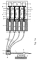
- the described embodiment of the device consists, as in 1 a and 1 b, from an infusion needle 1, which via a mixing chamber 36, four check valves 3, four Hoses 4 and four pressure sensors 2 to four disposable syringes 5 the metering device 6 is connected.
- a reflux preventing check valve 3 is connected, is an actuation in either direction without turning or exchanging the Check valve 3 not possible.
- Limit switches 12 are used the limitation of the feed movement of the piston 10 in each of both directions 8.
- the displacement sensor 11 behind the piston 10, while the drive 9 below the piston 10 is positioned and via driver 17 the Piston moves (see also Fig. 2).
- the displacement sensor 11 the illustrated embodiment, a linear potentiometer.
- the displacement sensor 11 come in MRI use with the same arrangement of Displacement sensors 11 according to FIG. 1 b also optoelectronic path measuring method for use.
- Fig. 2 shows the embodiment of the metering device 6 in perspective Sectional view with changeable magazine 7, the disposable syringes 5 with piston 10 and the drive 9 of several parts.
- the drive with an electric motor 15 equipped, which via a spindle drive 16 with driver 17, the piston 10 moves.
- this pneumatic or hydraulic offer Turbo drives, single-sided or double-acting hydraulic or pneumatic pressure piston drives or restricted Also drop cardan, bowden cable or pulley drives to outside MRT electric drives and piezo drives.
- the injection needle 1 is, as shown in Fig. 1 a, in a reversibly deliverable and detachable needle gripper 13 clamped.
- the needle gripper 13 is in turn on a driven Moving device 14 attached, which axially to the injection needle 1 is adjustable. This is the injection needle 1 with the needle gripper 13 in a certain path length displaceable. If the injection needle 1 further advanced be, the needle gripper 13 is released and with the traversing device 14 without injection needle 1utz ben to the Injection needle 1 pushed back to another place again to record and to advance this further. Depending on the length of the Injection needle 1, this process is repeatedly repeated.
- the particular advantage of this injection needle advancing device is its compact design while avoiding larger pistons or Linear drives.
- the system allows the placement of all system components in close proximity to the patient, i. within a CT or MRT's, so the dead volume in otherwise long drug delivery lines to minimize.
- Another advantage of this injection needle advancing device lies in the short free needle length between needle gripper 13 and puncture even for longer needle lengths, bringing the Risk of buckling especially thin flexible injection needles significantly reduced during the puncture.
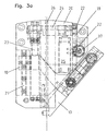
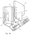
- Fig. 3 a and b show the injection needle advancing device without injection needle as a sectional view
- Fig. 4a and b as perspective view, wherein each designated a Figures the needle gripper 13 in the pushed back, the each with b designated figures the needle gripper 13 in advanced Show position.
- the traversing device consists from two carriages 18 and a rack 19, which with the Needle gripper 13 are connected and to two with the housing 20th the injection needle feeder attached rails 21st and are guided on a guide 22 in the housing 20.
- the adjustment movement takes place in the embodiment via a spindle drive 23, which via a belt 24 in the illustrated Embodiment of an electric motor 25 is driven.
- the position of the needle gripper 13 is in the illustrated form via a rotary potentiometer 37 with pinion, which measures the displacement of the needle gripper 13 in the rail 21 in the guide 22 via a rack.
- the injection needle is aligned and guided by guide rails 26 in the housing 20 in the axial direction, wherein the mixing chamber 36 shown in Figures 1 a and 1 b serves as a carrier of the injection needle 1 and the outer contour of the mixing chamber 36 with corresponding guide grooves 27 (see FIG and 1 b) must be equipped.
- the mixing chamber may also be fastened on a separate carrier, which is equipped as a separate component with the required guide grooves. In this case, the mixing chamber is detachable together with the injection needle and the hoses from the injection needle advancing device.
- the housing 20 is designed to be open in the region of the guide rails 26, so that it is accessible for insertion of the injection needle into the injection needle advancing device and for the check valves 3 and 4 hoses from above, below and from the side and beyond the doctor the visual Control of the puncture process allows.
- This consists in particular of the two Jaws 27, which are guided on two guide pins 28 and by a synchronous counter-acting spindle drive 29 against each other to be moved.
- the spindle drive 29 is connected via a Belt driven by an electric motor 31, with a Limit switch 32 for switching off the electric motor 31, the disassembly movement the jaws 27 is limited to each other.
- the injection needle advancing device designed as a two-part design be, with the injection needle 1 and the needle gripper 13th constructive to the first, sterilizable assembly and the Anchor device 14 to the second, non-sterile assembly belong.
- the first assembly is after each engagement of second assembly to separate and sterilize while the second module with another sterile first Module can be upgraded and used again.
- the housing 20 of the hypodermic needle advancing device As shown in Fig. 6, on a C-arm guide 33 according to of the prior art guided by a motor and on a carrier 34 via the lying patient 35 manipulator controlled positioned.
- the C-bow guide 33 as well as on a not shown manipulator-controlled pivoting device for the carrier 34 thereby allow a pivoting of the injection needle advancing device for example, all room degrees of freedom around a fictitious, fixed puncture point 38, in the injection needle 1 einstechbar from different directions is.
- the metering device 6 is on the carrier 34 arranged near the hypodermic needle feed device, whereby the length of the tubes is considerably reduced.
- a short Length of the tubes causes in particular a minimization of Pressure changes and elasticity influences of the hoses and the Drugs in the tube and thus serves in particular the more accurate Dosage of the medication.
- the object of the described C-arm guide 33 namely the pivoting of the injection needle advancing device or another medical instrument, including one powered hinge bracket or turntable, combined with a computer-aided manipulator control feasible.
Abstract
Description
Die vorliegende Erfindung betrifft eine Vorrichtung für eine Injektion von medizinischen Präparaten, insbesondere Medikamenten oder Kontrastmitteln, in einen Patienten-körper während einer Untersuchung im Computertomographen, CT, Magnetresonaztomographen, MRT, oder mit Endoskop gemäß des Oberbegriffs des Anspruch 1. Die vorliegende Erfindung umfasst dabei auch einen Einsatz der Vorrichtung in einem Magnetresonanztompgraphen, MRT.The present invention relates to a device for a Injection of medicated preparations, in particular medicines or contrast agents, into a patient's body during an examination in computed tomography, CT, Magnetic resonance imaging, MRI, or with endoscope according to the The preamble of claim 1. The present invention comprises while also using the device in one Magnetic Resonance Compounds, MRI.
Bei der interventionellen Radiologie orientiert und überwacht der Arzt seine operativen Eingriffe mit Hilfe von bildgebenden Verfahren, beispielsweise mit Hilfe der CT und MRT. Üblicherweise liegt der Patient dabei auf einer Patientenliege, während der behandelnde Arzt den Eingriff am Bildschirm überwacht. Bei tomographischen Verfahren, wie z.B. der CT- und MRT-Verfahren sind dies zweidimensionale Schnittbilder durch den Patientenkörper, welche im geringen Abstand zueinander aufgenommen werden und zu einem dreidimensionalen Abbild, dem sogenannten Tomogramm, des Patientenkörper zusammengesetzt werden. Die erstellten Tomogramme zeigen die inneren Organe, Gewebe- und Knochenstrukturen im Detail. Dabei können beliebige Schnittbilder generiert werden. Zudem lassen sich beim CT durch Kippen der Gantry oder programmgesteuert beim MRT individuelle Schnittdarstellungen generieren.In interventional radiology oriented and monitored the doctor does his surgery with the help of imaging techniques, for example with the help of CT and MRI. Usually, the patient lies on a patient bed, while the attending physician performs the procedure on Screen monitors. In tomographic procedures, such as e.g. The CT and MRI procedures are two-dimensional Sectional images through the patient's body, which in the minor Distance from each other and be taken to a three-dimensional Image, the so-called tomogram, of the patient's body be assembled. The created tomograms show the internal organs, tissue and bone structures in the Detail. Any desired sectional images can be generated. In addition, the CT can be tilted by tilting the gantry or programmatically on MRI individual cross-sectional views to generate.
Anhand der tomographischen Daten legt der behandelnde Arzt seine Zugangsplanung des anschließend zu operierenden Organs fest und ermittelt im Falle einer bildgestützten und manipulatorgesteuerten Medikamentendosierung die Koordinaten und Dosierraten für den Einstich der Injektionsnadel und sendet diese an den Manipulator. Based on the tomographic data sets the doctor his access planning of the subsequently operated organ fixed and determined in the case of a picture-based and manipulator-controlled drug dosing the coordinates and dosing rates for the puncture of the injection needle and sends it to the manipulator.
Aus [1] ist ein derartiges Medikamentendosierungssystem bekannt, bei dem von zwei 65 ml Einwegspritzen Medikamente oder Kontrastmittel im wesentlichen über einen Schlauch und eine Injektionsnadel in den Patientenkörper injiziert werden. Die Betätigung der Einwegspritzen erfolgt, wie die technischen Angaben in [1] vermuten lassen, wahrscheinlich elektromotorisch über Linearantriebe. Ferner wird ein naheliegender Einsatz des Medikamentendosiersystems im MRT oder CT in [1] unter tomographischer Kontrolle nicht erwähnt, obwohl die Baugröße für einen Einsatz im Kanal eines Tomographen durchaus geeignet erscheint.From [1] such a drug dosing system is known, in the case of two 65 ml disposable syringes or contrast agent substantially via a hose and inject a hypodermic needle into the patient's body. The operation of the disposable syringes, as the technical data in [1], probably Electric motor via linear drives. Furthermore, a more obvious Use of the drug dosing system on MRI or CT in [1] not mentioned under tomographic control, although the size for use in the channel of a Tomographs seems quite suitable.
Ein manipulatorgesteuertes Medikamentendosierungssystem mit Injektionsnadel, welches für den Einsatz innerhalb eines CT's oder MRT's geeignet ist, ist dagegen nicht bekannt.A manipulator-controlled drug dosing system with Injection needle, which is suitable for use within a CT's or MRT's is suitable, however, is not known.
Der Erfindung liegt die Aufgabe zugrunde, eine Vorrichtung für eine Injektion von medizinischen Präparaten gegenüber des zuletzt genannten Stands der Technik so zu modifizieren, dass diese als gesamte Einheit in einen Tomographen einschiebbar und in diesem bildgestützt einsetzbar ist.The invention has for its object to provide a device for an injection of medical preparations compared to the last one state of the art to modify so that these as a whole unit in a tomograph insertable and in this image-based is used.
Die Aufgabe wird durch die in Anspruch 1 beschriebene Vorrichtung gelöst. Die weiteren Ansprüche geben bevorzugte Ausgestaltungen der Vorrichtung an.The object is achieved by the device described in claim 1 solved. The further claims give preferred embodiments to the device.
Die erfindungsgemäße Vorrichtung für eine Injektion von medizinischen
Präparaten wird im folgenden anhand von Zeichnungen
einer Ausführungsform mit vier Einwegspritzen erläutert. Es zeigen
Die beschriebene Ausführungsform der Vorrichtung besteht, wie in
den Figuren 1 a und 1 b dargestellt, aus einer Infusionsnadel 1,
welche über eine Mischkammer 36, vier Rückschlagventile 3, vier
Schläuche 4 und vier Drucksensoren 2 an vier Einwegspritzen 5
der Dosiervorrichtung 6 angeschlossen ist. Dabei sind die vier
Einwegspritzen 5 in der Dosiervorrichtung 6 in ein Wechselmagazin
7 reversibel einlegbar und über je einen Antrieb 9, welcher
jeden Kolben 10 jeder Einwegspritze 5 einzeln in beiden Richtungen
8 verschieben kann, betätigbar. Solange jedoch zwischen jeder
Einwegspritze 5 und der Infusionsnadel 1 ein einen Rückfluss
verhinderndes Rückschlagventil 3 geschaltet ist, ist eine Betätigung
in beiden Richtungen ohne ein Umdrehen oder Austausch des
Rückschlagventils 3 nicht möglich. Bei Betätigung einer Spritze
wird der Injektionsfluss über die Zustellbewegung des Kolbens 10
über einen Wegsensor 11 sowie über eine Druckmessung am Drucksensor
2 kontinuierlich überwacht. Endschalter 12 dienen dabei
der Begrenzung der Zustellbewegung der Kolben 10 in jede der
beiden Richtungen 8.The described embodiment of the device consists, as in
1 a and 1 b, from an infusion needle 1,
which via a
Im Gegensatz zu der in Fig. 1 a dargestellten Prinzipskizze ist
in der perspektivischen Darstellung gemäß Fig. 1 b der Wegsensor
11 hinter dem Kolben 10 angeordnet, während der Antrieb 9 unterhalb
der Kolben 10 positioniert ist und über Mitnehmer 17 die
Kolben bewegt (vgl. auch Fig. 2). Ferner ist der Wegsensor 11
der dargestellten Ausführungsform ein lineares Potentiometer.
Alternativ kommen bei MRT-Einsatz bei gleicher Anordnung der
Wegsensoren 11 gemäß Fig. 1 b auch optoelektronische Wegmessverfahren
zum Einsatz.In contrast to the schematic diagram shown in Fig. 1 a
in the perspective view of FIG. 1 b, the
Fig. 2 zeigt die Ausführungsform der Dosiervorrichtung 6 in perspektivischer
Schnittdarstellung mit Wechselmagazin 7, die Einwegspritzen
5 mit Kolben 10 und dem Antrieb 9 aus mehreren Teilen.
In der dargestellten Ausführungsform ist der Antrieb mit
einem Elektromotor 15 ausgestattet, welcher über einen Spindeltrieb
16 mit Mitnehmer 17 die Kolben 10 bewegt.Fig. 2 shows the embodiment of the
Soll die Dosiervorrichtung 6 in einem MRT einsetzbar sein, sind
zur Vermeidung von magnetischen Störungen für die Dosiervorrichtung
6 ausschließlich nicht magnetisierbare Komponenten einsetzbar.
Als Antriebe bieten sich hierzu pneumatische oder hydraulische
Turboantriebe, einseitig oder beidseitig wirkende hydraulische
oder pneumatische Druckkolbenantriebe oder im eingeschränkten
Fall auch Kardan-, Bowdenzug- oder Seilzugantriebe zu außerhalb
des MRT liegenden Elektroantrieben sowie Piezoantriebe an.If the
Die Injektionsnadel 1 wird, wie in Fig. 1 a dargestellt, in einem
reversibel zustellbaren und wieder lösbaren Nadelgreifer 13
eingespannt. Der Nadelgreifer 13 ist wiederum auf einer angetriebenen
Verfahrvorrichtung 14 befestigt, welcher axial zur Injektionsnadel
1 verstellbar ist. Auf diese Weise ist die Injektionsnadel
1 mit dem Nadelgreifer 13 in einer bestimmten Weglänge
verschiebbar. Soll die Injektionsnadel 1 weiter vorgeschoben
werden, wird der Nadelgreifer 13 gelöst und mit der Verfahrvorrichtung
14 ohne Injektionsnadel 1 zurückgescho-ben, um die
Injektionsnadel 1 an zurückgeschobener anderen Stelle wieder
aufzunehmen und diese weiter vorzuschieben. Je nach Länge der
Injektionsnadel 1 ist dieser Vorgang mehrfach wiederholbar. The injection needle 1 is, as shown in Fig. 1 a, in a
reversibly deliverable and
Der besondere Vorteil dieser Injektionsnadelvorschubvorrichtung ist dessen kompakte Bauart unter Vermeidung größerer Kolben oder Linearantriebe. Somit sind die sehr beengten Platzverhältnisse in einem Kanal insbesondere eines MRT's ohne Einschränkung des Vorschubbereiches der Injektionsnadel 1 in vorteilhafter Weise nutzbar. Das System erlaubt die Platzierung aller Systemkomponenten in direkter Patientennähe, d.h. innerhalb eines CT's oder MRT's, um so das Totvolumen in sonst langen Medikamentenzuleitungen zu minimieren.The particular advantage of this injection needle advancing device is its compact design while avoiding larger pistons or Linear drives. Thus, the very cramped space in a channel, in particular of an MRT without limitation of Feed range of the injection needle 1 in an advantageous manner available. The system allows the placement of all system components in close proximity to the patient, i. within a CT or MRT's, so the dead volume in otherwise long drug delivery lines to minimize.
Ein weiterer Vorteil dieser Injektionsnadelvorschubvorrichtung
liegt in der kurzen freien Nadellänge zwischen Nadelgreifer 13
und Einstichpunkt auch für längere Nadellängen, womit sich die
Gefahr eines Ausknickens vor allem dünner biegsamer Injektionsnadeln
während des Einstichs erheblich reduziert.Another advantage of this injection needle advancing device
lies in the short free needle length between
Fig. 3 a und b zeigen die Injektionsnadelvorschubvorrichtung
ohne Injektionsnadel als Schnittdarstellung, Fig. 4a und b als
perspektivische Darstellung, wobei die jeweils mit a bezeichneten
Figuren den Nadelgreifer 13 in der zurückgeschobenen, die
jeweils mit b bezeichneten Figuren den Nadelgreifer 13 in vorgeschobenen
Position zeigen. Die Verfahrvorrichtung besteht dabei
aus zwei Schlitten 18 und einer Zahnstange 19, welche mit dem
Nadelgreifer 13 verbunden sind sowie auf zwei mit dem Gehäuse 20
der Injektionsnadelvorschubvorrichtung befestigten Schienen 21
sowie auf einer Führung 22 im Gehäuse 20 geführt sind. Die Verstellbewegung
erfolgt im Ausführungsbeispiel über einen Spindelantrieb
23, welcher über einen Riemen 24 in der dargestellten
Ausführungsform von einem Elektromotor 25 angetrieben wird.Fig. 3 a and b show the injection needle advancing device
without injection needle as a sectional view, Fig. 4a and b as
perspective view, wherein each designated a
Figures the
Die Position des Nadelgreifers 13 wird in der dargestellten Form
über ein Drehpotentiometer 37 mit Ritzel, welches über eine
Zahnstange die Verschiebung des Nadelgreifers 13 in der Schiene
21 in der Führung 22 misst, bestimmt.
Die Injektionsnadel wird durch Führungsleisten 26 im Gehäuse 20
in axialer Richtung ausgerichtet und geführt, wobei die in Figuren
1 a und 1 b dargestellte Mischkammer 36 als Träger der Injektionsnadel
1 dient und die Außenkontur der Mischkammer 36 mit
entsprechenden Führungsnuten 27 (siehe Fig. 1 a und 1 b) ausgestattet
sein muss. Alternativ hierzu kann die Mischkammer auch
auf einem separaten Träger, welches als separates Bauteil mit
den erforderlichen Führungsnuten ausgestattet ist, befestigt
sein. In diesem Fall ist die Mischkammer gemeinsam mit der Injektionsnadel
und den Schläuchen von der Injektionsnadelvorschubvorrichtung
lösbar. Das Gehäuse 20 ist im Bereich der Führungsleisten
26 offen gestaltet, sodass diese für ein Einsetzen
der Injektionsnadel in die Injektionsnadelvorschub-vorrichtung
sowie für die Rückschlagventile 3 und Schläuche 4 von oben, unten
und von der Seite her zugänglich ist und darüber hinaus dem
Arzt die visuelle Kontrolle des Einstichvorganges ermöglicht.The position of the
The injection needle is aligned and guided by
Einen Schnitt durch der Nadelgreifer 13 zeigt Fig. 5 in einer
Schnittdarstellung. Diese besteht insbesondere aus den beiden
Backen 27, welche auf zwei Führungsstiften 28 geführt werden und
durch einen synchron gegenläufig wirkenden Spindelantrieb 29 gegeneinander
bewegt werden. Der Spindelantrieb 29 wird über einen
Riemen von einem Elektromotor 31 angetrieben, wobei mit einem
Endschalter 32 zum Abschalten des Elektromotors 31 die Auseinanderbewegung
der Backen 27 zueinander begrenzt wird.A section through the
Für einen Einsatz dieser Injektionsnadelvorschubvorrichtung am Patienten im Kanal eines MRT sind zur Vermeidung von magnetischen Störungen ausschließlich nicht magnetisierbare Komponenten einsetzbar. Somit müssen auch sämtliche Elektromotoren durch pneumatische oder hydraulische Turboantriebe, Piezoantriebe, einseitig oder beidseitig wirkende hydraulische oder pneumatische Druckkolbenantriebe oder im eingeschränkten Fall auch durch. Kardan-, Bowdenzug- oder Seilzugantriebe zu außerhalb des MRT liegenden Elektroantrieben ersetzt werden.For use of this injection needle advancing device on Patients in the channel of an MRI are to avoid magnetic Disturbances only non-magnetizable components used. Thus, all electric motors through pneumatic or hydraulic turbo drives, piezo drives, single-sided or double-acting hydraulic or pneumatic Pressure piston drives or in a limited case by. Cardan, Bowden cable or cable drives to outside the MRT replaced electric drives.
Für eine bessere Sterilisierbarkeit kann die Injektionsnadelvorschubvorrichtung
als zweigeteilte Bauform ausgeführt
werden, wobei die Injektionsnadel 1 und der Nadelgreifer 13
konstruktiv zur ersten, sterilisierbaren Baugruppe und die
Vorfahrvorrichtung 14 zur zweiten, nicht sterilen Baugruppe
gehören. Die erste Baugruppe ist nach jedem Eingriff von
zweiten Baugruppe zu trennen und zu sterilisieren, während
den zweiten Baugruppe mit einer weiteren sterilen ersten
Baugruppe aufrüstbar und damit wieder einsetzbar ist.For improved sterilizability, the injection needle advancing device
designed as a two-part design
be, with the injection needle 1 and the needle gripper 13th
constructive to the first, sterilizable assembly and the
Für den beengten Einsatz der erfindungsgemäßen Vorrichtung im CT
oder MRT wird das Gehäuse 20 der Injektionsnadelvorschubvorrichtung,
wie in Fig. 6 dargestellt, auf einer C-Bogenführung 33 gemäß
des Standes der Technik motorisch verfahrbar geführt und auf
einem Träger 34 über den liegenden Patienten 35 manipulatorgesteuert
positioniert. Die C-Bogenführung 33 sowie die auf einer
nicht dargestellten manipulatorgesteuerten Schwenkvorrichtung
für den Träger 34 ermöglichen dabei eine Schwenkung der Injektionsnadelvorschubvorrichtung
um alle Raumfreiheitsgrade beispielsweise
um einen fiktiven, ortsfesten Einstichpunkt 38, in
den die Injektionsnadel 1 aus verschiedenen Richtungen einstechbar
ist. Ferner ist die Dosiervorrichtung 6 auf dem Träger 34
nahe der Injektionsnadelvorschubvorrichtung angeordnet, womit
die Länge der Schläuche erheblich reduzierbar ist. Eine kurze
Länge der Schläuche bewirkt insbesondere eine Minimierung von
Druckänderungen und Elastizitätseinflüssen der Schläuche und der
Medikamente im Schlauch und dient damit insbesondere der genaueren
Dosierung der Medikamente.For the cramped use of the device according to the invention in CT
or MRT is the
Alternativ ist die Aufgabe der beschriebenen C-Bogenführung 33,
nämlich die Schwenkung der Injektionsnadelvorschubvorrichtung
oder eines anderen medizinischen Instrumentes, auch mit einer
angetriebenen Gelenkhalterung oder Drehscheibe, kombiniert mit
einer rechnergestützten Manipulatorsteuerung realisierbar.Alternatively, the object of the described C-
Ferner ist an den Träger 34 ein Sensor 39 befestigt, welcher
über eine Haltevorrichtung 40 auf der Höhe des fiktiven Einstichpunktes
38 so ausgerichtet wird, dass das Messvolumen um
diesen fiktiven Einstichpunkt 38 liegt. Beispielsweise kann dieser
Sensor als ringförmiger Kontaktsensor ausgebildet sein, wobei
der fiktive Einstichpunkt 38 innerhalb der Ringfläche liegt.
Auf diese Weise lässt sich der fiktive Einstichpunkt 38 exakt
auf einer Oberfläche, beispielsweise der Hautoberfläche des Patienten
35 anfahren. Der Patient 35 kann sich somit durch den
Kontakt des Sensors 39 auf der Haut auf den bevorstehenden Einstich
vorbereiten, womit sich die Gefahr eines Zuckens des Patienten
beim Einstich erheblich reduziert. Der Sensor 39 überwacht
somit die Bewegung des Patienten. Unterstützend oder alternativ
hierzu kann auf dieser Oberfläche eine sensorisch erkennbare
Markierung aufgetragen sein, welche mit nicht dargestellten optischen
Detektoren erkennbar ist und manipulatorgesteuert mit
dem fiktiven Einstichpunkt der Injektions-nadel in Übereinstimmung
bringbar ist.
- 11
- Infusionsnadelinfusion needle
- 22
- Drucksensorpressure sensor
- 33
- Rückschlagventilcheck valve
- 44
- Schlauchtube
- 55
- Einwegspritzedisposable syringe
- 66
- Dosiervorrichtungmetering
- 77
- Wechselmagazinchanging magazine
- 88th
- Richtungdirection
- 99
- Antriebdrive
- 1010
- Kolbenpiston
- 1111
- Wegsensordisplacement sensor
- 1212
- Endschalterlimit switch
- 1313
- Nadelgreiferneedle grippers
- 1414
- Verfahrvorrichtungtraversing
- 1515
- Elektromotorelectric motor
- 1616
- Spindeltriebspindle drive
- 1717
- Mitnehmertakeaway
- 1818
- Schlittencarriage
- 1919
- Zahnstangerack
- 2020
- Gehäusecasing
- 2121
- Schienerail
- 2222
- Führungguide
- 2323
- Spindelantriebspindle drive
- 2424
- Riemenbelt
- 2525
- Elektromotorelectric motor
- 2626
- Führungsleistenguide rails
- 2727
- Backento bake
- 2828
- Führungsstifteguide pins
- 2929
- Spindelantriebspindle drive
- 3030
- Riemenbelt
- 3131
- Elektromotorelectric motor
- 3232
- Endschalterlimit switch
- 3333
- C-BogenführungC-arm guidance
- 3434
- Trägercarrier
- 3535
- Patientpatient
- 3636
- Mischkammermixing chamber
- 3737
- DrehpotentiometerRotary
- 3838
- Fiktiver EinstichpunktFictitious puncture point
- 3939
- Sensorsensor
- 4040
- Haltevorrichtungholder
Claims (7)
- Device for the injection of medical substances into a patient's body during an examination in a computer tomograph, CT, or in the magnetic resonance tomograph, MRT, or during an endoscopic examination, consisting ofcharacterized bya) an injection needle (1) withb) a separate dosage unit (6) for the storage and sensor-controlled metering of the medical substances, with this dosage unit (6) having such geometrical dimensions and being equipped with such materials, sensors, and driving technology that it can also be pushed into the CT or MRT and works inside, as well asc) a hose (4) for the transport of the medical substances from the dosage unit (6) into the injection needle,d) the injection needle (1) being accommodated in an injection needle feed unit for stabbing the injection needle into the patient (35) and the simultaneous injection of medicine, with the injection needle feed unit of the injection needle (1) consisting of a needle guide unit, a needle gripper (13), and a linear drive (14) for shifting the needle gripper (13) with or without the injection needle parallel to the latter (1),e) the hose (4) being equipped with a check valve (3) for the one-way transport of the medical substances, andf) a pressure sensor (2) being installed between the dosage unit (6) and the injection needle (1) for infusion monitoring.
- Device according to claim 1, with all components of the device being made of non-magnetic materials and the drives of the device neither needing nor generating a magnetic or electric field, but representing pneumatic or hydraulic drives or piezodrives, or a driving force generated outside of the MRT being transmitted mechanically to the device using cardan, Bowden wire or rope drives or force transmission taking place hydraulically or pneumatically by pressure piston drives.
- Device according to claim 1 or 2, with the injection needle (1) being movable around a fictitious insertion point (38) in all spatial degrees of freedom due to the use of sluing mechanisms.
- Device according to claim 3, characterized by a pneumatic or hydraulic or optoelectronic sensor (39) lying on the skin of the patient and being located around and on the level of the fictitious insertion point (38).
- Device according to one of claims 1 through 4, characterized by the dosage unit (6) containing an exchange magazine (7) for the correct insertion and re-filling of one of the disposable syringes (5) and a drive (9) with pins (17) for the actuation of the syringe.
- Device according to claim 5, characterized by the fact that several disposable syringes (5) may be inserted into the magazine (7) and that these syringes may be actuated separately by an own drive (9) with pins (17) in the dosage unit (6), with each syringe being connected with the mixing chamber (36) of the joint injection needle (1) via a separate hose (4), and each of these hoses (4) being equipped with a check valve (3) that is located upstream of the connection of the injection needle.
- Device according to one of claims 1 through 4, characterized by the injection needle feed unit being designed in a modular manner with two parts, with the injection needle (1) and the needle gripper (13) being accommodated in the first, sterilizable part and the feed unit (14) belonging to the second, non-sterile part.
Applications Claiming Priority (3)
| Application Number | Priority Date | Filing Date | Title |
|---|---|---|---|
| DE10030620 | 2000-06-28 | ||
| DE10030620A DE10030620A1 (en) | 2000-06-28 | 2000-06-28 | Device for injecting medical preparations under CT / MRI control |
| PCT/EP2001/006996 WO2002000276A1 (en) | 2000-06-28 | 2001-06-21 | Device for injection of medical preparations with ct/mri monitoring |
Publications (2)
| Publication Number | Publication Date |
|---|---|
| EP1294419A1 EP1294419A1 (en) | 2003-03-26 |
| EP1294419B1 true EP1294419B1 (en) | 2005-05-04 |
Family
ID=7646541
Family Applications (1)
| Application Number | Title | Priority Date | Filing Date |
|---|---|---|---|
| EP01965018A Expired - Lifetime EP1294419B1 (en) | 2000-06-28 | 2001-06-21 | Device for injection of medical preparations with ct/mri monitoring |
Country Status (7)
| Country | Link |
|---|---|
| US (1) | US7566321B2 (en) |
| EP (1) | EP1294419B1 (en) |
| JP (1) | JP3769539B2 (en) |
| AT (1) | ATE294605T1 (en) |
| CA (1) | CA2412496A1 (en) |
| DE (2) | DE10030620A1 (en) |
| WO (1) | WO2002000276A1 (en) |
Families Citing this family (60)
| Publication number | Priority date | Publication date | Assignee | Title |
|---|---|---|---|---|
| US20050283214A1 (en) * | 2003-08-25 | 2005-12-22 | Biophan Technologies, Inc. | Medical device with an electrically conductive anti-antenna member |
| US20070173911A1 (en) * | 2001-02-20 | 2007-07-26 | Biophan Technologies, Inc. | Medical device with an electrically conductive anti-antenna member |
| US6949929B2 (en) | 2003-06-24 | 2005-09-27 | Biophan Technologies, Inc. | Magnetic resonance imaging interference immune device |
| US20070168006A1 (en) * | 2001-02-20 | 2007-07-19 | Biophan Technologies, Inc. | Medical device with an electrically conductive anti-antenna member |
| US20050288753A1 (en) * | 2003-08-25 | 2005-12-29 | Biophan Technologies, Inc. | Medical device with an electrically conductive anti-antenna member |
| US20050283167A1 (en) * | 2003-08-25 | 2005-12-22 | Biophan Technologies, Inc. | Medical device with an electrically conductive anti-antenna member |
| US20070168005A1 (en) * | 2001-02-20 | 2007-07-19 | Biophan Technologies, Inc. | Medical device with an electrically conductive anti-antenna member |
| US7553295B2 (en) | 2002-06-17 | 2009-06-30 | Iradimed Corporation | Liquid infusion apparatus |
| US7267661B2 (en) | 2002-06-17 | 2007-09-11 | Iradimed Corporation | Non-magnetic medical infusion device |
| US7404809B2 (en) | 2004-10-12 | 2008-07-29 | Iradimed Corporation | Non-magnetic medical infusion device |
| US7388378B2 (en) * | 2003-06-24 | 2008-06-17 | Medtronic, Inc. | Magnetic resonance imaging interference immune device |
| US7839146B2 (en) | 2003-06-24 | 2010-11-23 | Medtronic, Inc. | Magnetic resonance imaging interference immune device |
| US20050050042A1 (en) * | 2003-08-20 | 2005-03-03 | Marvin Elder | Natural language database querying |
| US7344559B2 (en) * | 2003-08-25 | 2008-03-18 | Biophan Technologies, Inc. | Electromagnetic radiation transparent device and method of making thereof |
| US8868212B2 (en) * | 2003-08-25 | 2014-10-21 | Medtronic, Inc. | Medical device with an electrically conductive anti-antenna member |
| US20050288756A1 (en) * | 2003-08-25 | 2005-12-29 | Biophan Technologies, Inc. | Medical device with an electrically conductive anti-antenna member |
| US20050288755A1 (en) * | 2003-08-25 | 2005-12-29 | Biophan Technologies, Inc. | Medical device with an electrically conductive anti-antenna member |
| US20050288754A1 (en) * | 2003-08-25 | 2005-12-29 | Biophan Technologies, Inc. | Medical device with an electrically conductive anti-antenna member |
| US20050288751A1 (en) * | 2003-08-25 | 2005-12-29 | Biophan Technologies, Inc. | Medical device with an electrically conductive anti-antenna member |
| DE102004021035B3 (en) * | 2004-04-07 | 2005-11-17 | Erbe Elektromedizin Gmbh | Apparatus for waterjet surgery |
| DE102004039020B4 (en) * | 2004-08-11 | 2018-01-25 | Tecpharma Licensing Ag | autoinjector |
| WO2006023700A2 (en) * | 2004-08-20 | 2006-03-02 | Biophan Technologies, Inc. | Magnetic resonance imaging interference immune device |
| CN101076284A (en) * | 2004-12-13 | 2007-11-21 | 皇家飞利浦电子股份有限公司 | Cannula inserting system |
| FR2882514B1 (en) * | 2005-02-28 | 2008-02-15 | Inst Nat Sciences Appliq | DEVICE FOR MAINTAINING AND DISPLACING CONTROL IN TRANSLATION OF AN EXTENDED BODY |
| US20070010736A1 (en) * | 2005-05-19 | 2007-01-11 | Biophan Technologies, Inc. | Electromagnetic resonant circuit sleeve for implantable medical device |
| US9011473B2 (en) | 2005-09-07 | 2015-04-21 | Ulthera, Inc. | Dissection handpiece and method for reducing the appearance of cellulite |
| US8518069B2 (en) | 2005-09-07 | 2013-08-27 | Cabochon Aesthetics, Inc. | Dissection handpiece and method for reducing the appearance of cellulite |
| US9358033B2 (en) | 2005-09-07 | 2016-06-07 | Ulthera, Inc. | Fluid-jet dissection system and method for reducing the appearance of cellulite |
| US7967763B2 (en) | 2005-09-07 | 2011-06-28 | Cabochon Aesthetics, Inc. | Method for treating subcutaneous tissues |
| US10548659B2 (en) | 2006-01-17 | 2020-02-04 | Ulthera, Inc. | High pressure pre-burst for improved fluid delivery |
| US9486274B2 (en) | 2005-09-07 | 2016-11-08 | Ulthera, Inc. | Dissection handpiece and method for reducing the appearance of cellulite |
| US20080200864A1 (en) * | 2005-12-02 | 2008-08-21 | Cabochon Aesthetics, Inc. | Devices and methods for selectively lysing cells |
| US20080014627A1 (en) * | 2005-12-02 | 2008-01-17 | Cabochon Aesthetics, Inc. | Devices and methods for selectively lysing cells |
| US20080200863A1 (en) * | 2005-12-02 | 2008-08-21 | Cabochon Aesthetics, Inc. | Devices and methods for selectively lysing cells |
| US9248317B2 (en) * | 2005-12-02 | 2016-02-02 | Ulthera, Inc. | Devices and methods for selectively lysing cells |
| US20080197517A1 (en) * | 2005-12-02 | 2008-08-21 | Cabochon Aesthetics, Inc. | Devices and methods for selectively lysing cells |
| US20080195036A1 (en) * | 2005-12-02 | 2008-08-14 | Cabochon Aesthetics, Inc. | Devices and methods for selectively lysing cells |
| US7885793B2 (en) | 2007-05-22 | 2011-02-08 | International Business Machines Corporation | Method and system for developing a conceptual model to facilitate generating a business-aligned information technology solution |
| DE102006006952A1 (en) * | 2006-02-14 | 2007-08-23 | E-Z-Em, Inc. | MRI system |
| US8768486B2 (en) | 2006-12-11 | 2014-07-01 | Medtronic, Inc. | Medical leads with frequency independent magnetic resonance imaging protection |
| US7976469B2 (en) * | 2007-06-04 | 2011-07-12 | Medtronic, Inc. | Percutaneous needle guide |
| US8105282B2 (en) | 2007-07-13 | 2012-01-31 | Iradimed Corporation | System and method for communication with an infusion device |
| US8439940B2 (en) | 2010-12-22 | 2013-05-14 | Cabochon Aesthetics, Inc. | Dissection handpiece with aspiration means for reducing the appearance of cellulite |
| FR2923393B1 (en) * | 2007-11-12 | 2010-01-08 | Doran Int | DEVICE FOR ADMINISTERING MULTIPLE MEDICAL TREATMENT LIQUIDS TO A PATIENT |
| JP5695908B2 (en) * | 2007-12-10 | 2015-04-08 | バイエル メディカル ケア インコーポレーテッド | Continuous fluid transport system and fluid transport method |
| US11096708B2 (en) | 2009-08-07 | 2021-08-24 | Ulthera, Inc. | Devices and methods for performing subcutaneous surgery |
| US9358064B2 (en) | 2009-08-07 | 2016-06-07 | Ulthera, Inc. | Handpiece and methods for performing subcutaneous surgery |
| US8568446B2 (en) | 2010-05-13 | 2013-10-29 | Ethicon Endo-Surgery, Inc. | Multi-chamber therapeutic cell applicator instrument |
| US8486155B2 (en) | 2010-05-13 | 2013-07-16 | Ethicon Endo-Surgery, Inc. | Fistula repair plug having multiple layers |
| US8491526B2 (en) * | 2010-05-13 | 2013-07-23 | Ethicon Endo-Surgery, Inc. | Therapeutic cell applicator instrument with modular tips |
| WO2013043889A1 (en) | 2011-09-21 | 2013-03-28 | Medrad, Inc. | System and assembly method for a fluid pump device for a continuous multi-fluid delivery system |
| BE1020228A3 (en) * | 2011-10-12 | 2013-06-04 | Mepy Benelux Bvba | A NEEDLE GUIDE AND METHOD FOR DETERMINING THE POSITION OF A NEEDLE MOSTLY IN A SUCH NEEDLE GUIDE FITTED TO AN IMAGE CONDITIONER. |
| CN102715955B (en) * | 2012-06-11 | 2014-05-14 | 北京航空航天大学 | Hydraulic and servo-motor hybrid-drive system for medical robot |
| CN105492052B (en) * | 2013-09-05 | 2019-06-14 | 赛诺菲-安万特德国有限公司 | Driving mechanism for needle insertion assembly |
| DE102014101763A1 (en) * | 2014-02-12 | 2015-08-13 | IDTM GmbH | injection device |
| EP3242649A4 (en) | 2015-01-09 | 2019-01-09 | Bayer Healthcare LLC | Multiple fluid delivery system with multi-use disposable set and features thereof |
| CN105536093B (en) * | 2016-03-10 | 2019-05-03 | 京东方科技集团股份有限公司 | Transfusion system and the infusion method for using transfusion system |
| US11268506B2 (en) | 2017-12-22 | 2022-03-08 | Iradimed Corporation | Fluid pumps for use in MRI environment |
| CN113694304B (en) * | 2021-08-27 | 2023-02-10 | 诸暨市人民医院 | Medical injection device with lifting function |
| WO2023154908A2 (en) * | 2022-02-11 | 2023-08-17 | Board Of Regents, The University Of Texas System | Convection-enhanced thermo-chemotherapy catheter system |
Family Cites Families (12)
| Publication number | Priority date | Publication date | Assignee | Title |
|---|---|---|---|---|
| EP0465609A4 (en) * | 1989-11-27 | 1992-08-26 | Bard International, Inc. | Puncture guide for computer tomography |
| US5469847A (en) * | 1992-09-09 | 1995-11-28 | Izi Corporation | Radiographic multi-modality skin markers |
| US5579767A (en) * | 1993-06-07 | 1996-12-03 | Prince; Martin R. | Method for imaging abdominal aorta and aortic aneurysms |
| US5494036A (en) * | 1993-11-26 | 1996-02-27 | Medrad, Inc. | Patient infusion system for use with MRI |
| EP0813393B1 (en) * | 1995-03-10 | 1998-09-16 | Forschungszentrum Karlsruhe GmbH | Device for guiding surgical instruments for endoscopic surgery |
| IL130057A (en) * | 1996-11-29 | 2004-03-28 | Endocare Inc | Apparatus for guiding medical instruments during ultransonographic imaging |
| ES2252871T3 (en) * | 1997-11-07 | 2006-05-16 | Acist Medical Systems, Inc. | ANGIOGRAPHIC INJECTOR SYSTEM WITH MULTIPLE FLUID PROCESSOR. |
| US6391005B1 (en) * | 1998-03-30 | 2002-05-21 | Agilent Technologies, Inc. | Apparatus and method for penetration with shaft having a sensor for sensing penetration depth |
| DE19855293C1 (en) * | 1998-11-24 | 2000-05-04 | Ethicon Endo Surgery Europe | Biopsy system for taking and examining patient tissue samples has a biopsy unit which can be mounted together with a diagnostic unit such as an X-ray unit to save both time and space in obtaining results |
| US6339718B1 (en) * | 1999-07-30 | 2002-01-15 | Medrad, Inc. | Programmable injector control |
| US6565533B1 (en) * | 2000-01-21 | 2003-05-20 | Novus International, Inc. | Inoculation apparatus and method |
| US6508791B1 (en) * | 2000-01-28 | 2003-01-21 | Ramon Guerrero | Infusion device cartridge |
-
2000
- 2000-06-28 DE DE10030620A patent/DE10030620A1/en not_active Withdrawn
-
2001
- 2001-06-21 AT AT01965018T patent/ATE294605T1/en not_active IP Right Cessation
- 2001-06-21 WO PCT/EP2001/006996 patent/WO2002000276A1/en active IP Right Grant
- 2001-06-21 CA CA002412496A patent/CA2412496A1/en not_active Abandoned
- 2001-06-21 EP EP01965018A patent/EP1294419B1/en not_active Expired - Lifetime
- 2001-06-21 DE DE50106118T patent/DE50106118D1/en not_active Expired - Fee Related
- 2001-06-21 JP JP2002505057A patent/JP3769539B2/en not_active Expired - Fee Related
-
2002
- 2002-12-26 US US10/330,037 patent/US7566321B2/en not_active Expired - Fee Related
Also Published As
| Publication number | Publication date |
|---|---|
| DE50106118D1 (en) | 2005-06-09 |
| WO2002000276A8 (en) | 2004-02-26 |
| US20030171670A1 (en) | 2003-09-11 |
| ATE294605T1 (en) | 2005-05-15 |
| EP1294419A1 (en) | 2003-03-26 |
| US7566321B2 (en) | 2009-07-28 |
| JP2004516859A (en) | 2004-06-10 |
| CA2412496A1 (en) | 2002-12-23 |
| DE10030620A1 (en) | 2002-01-17 |
| WO2002000276A1 (en) | 2002-01-03 |
| JP3769539B2 (en) | 2006-04-26 |
Similar Documents
| Publication | Publication Date | Title |
|---|---|---|
| EP1294419B1 (en) | Device for injection of medical preparations with ct/mri monitoring | |
| EP1296609B1 (en) | Medical device for stereotaxis and patient positioning | |
| AT412837B (en) | SYSTEM FOR INJECTING OR SUCKING A FLUID | |
| EP1267732A1 (en) | Medical device with a drive unit for a needle | |
| EP3041430B1 (en) | Device for attaching medical target devices and the like | |
| EP1904127A1 (en) | Injection appliance and method | |
| DE19505276A1 (en) | Computer tomography for use in operating theatre | |
| DE102012215922A1 (en) | Medical system for producing projections and/or three-dimensional volume datasets of interior of stroke patient in hospital, has computed tomography device and X-ray device provided with detectors and X-ray sources, respectively | |
| WO2002013709A1 (en) | Device for navigating and positioning medical instruments in magnetic resonance tomographs | |
| DE10030507C2 (en) | Manipulator for interventional and operative interventions under CT / MRI control | |
| DE19905239A1 (en) | Positioning unit for magnetic resonance tomography installations simultaneously serves patient's support, and functions in combination with automatically controllable positioning system of medicinal instruments | |
| EP1075216B1 (en) | Magnetic resonance tomograph | |
| EP1729843A1 (en) | Remote-controlled needle guide | |
| DE10015510C2 (en) | Medical device with a drive device for a needle | |
| EP4346687A1 (en) | Instrument advancing device and use of a spindle device in an instrument advancing device | |
| DE102015207119A1 (en) | Interventional positioning kinematics | |
| EP4081124A1 (en) | Computer-assisted tomography system | |
| DE102007017517B4 (en) | Navigable endoscopy capsule | |
| DE102013004062A1 (en) | Device for needle feeding, particularly for introduction of puncture needles in patients, has needle guidance provided with lifting cylinder, which is connected with master cylinder over fluid-filled hose | |
| DE19701346A1 (en) | Mobile medical system e.g. for X-ray appts. | |
| DE19938955B4 (en) | Device for gentle, at least partially automated removal of biological tissue from a body | |
| DE102007059601B4 (en) | Diagnostic device comprising an imaging diagnostic device and an electromagnetic localization system and method for processing diagnostic image data | |
| DE202004020726U1 (en) | Hydraulic dosing device for manually injecting a medical preparation into a body, comprises an injection unit, a master cylinder, a slave cylinder, a hydraulic connection and a mechanical coupling | |
| DE112018003467T5 (en) | MEDICAL DEVICE FOR REDUCED PENETRATION FORCE FOR VASCULAR ACCESS | |
| DE112016003081T5 (en) | Device with reduced force for intravascular access and guidewire placement |
Legal Events
| Date | Code | Title | Description |
|---|---|---|---|
| PUAI | Public reference made under article 153(3) epc to a published international application that has entered the european phase |
Free format text: ORIGINAL CODE: 0009012 |
|
| 17P | Request for examination filed |
Effective date: 20021211 |
|
| AK | Designated contracting states |
Kind code of ref document: A1 Designated state(s): AT BE CH CY DE DK ES FI FR GB GR IE IT LI LU MC NL PT SE TR |
|
| RIN1 | Information on inventor provided before grant (corrected) |
Inventor name: KOEHN, SWEN Inventor name: GUMB, LOTHAR Inventor name: PROKOTT, GEORG Inventor name: HANNULA, HENRI Inventor name: SCHAEF, ARIBERT Inventor name: MELZER, ANDREAS |
|
| RIN1 | Information on inventor provided before grant (corrected) |
Inventor name: SCHAEF, ARIBERT Inventor name: HANNULA, HENRI Inventor name: GUMB, LOTHAR Inventor name: KOEHN, SWEN Inventor name: MELZER, ANDREAS Inventor name: PROKOTT, GEORG |
|
| 17Q | First examination report despatched |
Effective date: 20040318 |
|
| GRAP | Despatch of communication of intention to grant a patent |
Free format text: ORIGINAL CODE: EPIDOSNIGR1 |
|
| GRAS | Grant fee paid |
Free format text: ORIGINAL CODE: EPIDOSNIGR3 |
|
| GRAA | (expected) grant |
Free format text: ORIGINAL CODE: 0009210 |
|
| AK | Designated contracting states |
Kind code of ref document: B1 Designated state(s): AT BE CH CY DE DK ES FI FR GB GR IE IT LI LU MC NL PT SE TR |
|
| PG25 | Lapsed in a contracting state [announced via postgrant information from national office to epo] |
Ref country code: IE Free format text: LAPSE BECAUSE OF FAILURE TO SUBMIT A TRANSLATION OF THE DESCRIPTION OR TO PAY THE FEE WITHIN THE PRESCRIBED TIME-LIMIT Effective date: 20050504 Ref country code: TR Free format text: LAPSE BECAUSE OF FAILURE TO SUBMIT A TRANSLATION OF THE DESCRIPTION OR TO PAY THE FEE WITHIN THE PRESCRIBED TIME-LIMIT Effective date: 20050504 Ref country code: ES Free format text: LAPSE BECAUSE OF FAILURE TO SUBMIT A TRANSLATION OF THE DESCRIPTION OR TO PAY THE FEE WITHIN THE PRESCRIBED TIME-LIMIT Effective date: 20050504 Ref country code: NL Free format text: LAPSE BECAUSE OF FAILURE TO SUBMIT A TRANSLATION OF THE DESCRIPTION OR TO PAY THE FEE WITHIN THE PRESCRIBED TIME-LIMIT Effective date: 20050504 Ref country code: FI Free format text: LAPSE BECAUSE OF FAILURE TO SUBMIT A TRANSLATION OF THE DESCRIPTION OR TO PAY THE FEE WITHIN THE PRESCRIBED TIME-LIMIT Effective date: 20050504 |
|
| REG | Reference to a national code |
Ref country code: GB Ref legal event code: FG4D Free format text: NOT ENGLISH |
|
| RIN1 | Information on inventor provided before grant (corrected) |
Inventor name: HANNULA, HENRI Inventor name: MELZER, ANDREAS Inventor name: KOEHN, SWEN Inventor name: PROKOTT, GEORG Inventor name: SCHAEF, ARIBERT Inventor name: GUMB, LOTHAR |
|
| REG | Reference to a national code |
Ref country code: CH Ref legal event code: NV Representative=s name: ROTTMANN, ZIMMERMANN + PARTNER AG Ref country code: CH Ref legal event code: EP |
|
| REG | Reference to a national code |
Ref country code: IE Ref legal event code: FG4D Free format text: LANGUAGE OF EP DOCUMENT: GERMAN |
|
| REF | Corresponds to: |
Ref document number: 50106118 Country of ref document: DE Date of ref document: 20050609 Kind code of ref document: P |
|
| PG25 | Lapsed in a contracting state [announced via postgrant information from national office to epo] |
Ref country code: CY Free format text: LAPSE BECAUSE OF FAILURE TO SUBMIT A TRANSLATION OF THE DESCRIPTION OR TO PAY THE FEE WITHIN THE PRESCRIBED TIME-LIMIT Effective date: 20050621 Ref country code: LU Free format text: LAPSE BECAUSE OF NON-PAYMENT OF DUE FEES Effective date: 20050621 Ref country code: AT Free format text: LAPSE BECAUSE OF NON-PAYMENT OF DUE FEES Effective date: 20050621 |
|
| PG25 | Lapsed in a contracting state [announced via postgrant information from national office to epo] |
Ref country code: BE Free format text: LAPSE BECAUSE OF NON-PAYMENT OF DUE FEES Effective date: 20050630 Ref country code: MC Free format text: LAPSE BECAUSE OF NON-PAYMENT OF DUE FEES Effective date: 20050630 |
|
| PG25 | Lapsed in a contracting state [announced via postgrant information from national office to epo] |
Ref country code: DK Free format text: LAPSE BECAUSE OF FAILURE TO SUBMIT A TRANSLATION OF THE DESCRIPTION OR TO PAY THE FEE WITHIN THE PRESCRIBED TIME-LIMIT Effective date: 20050804 Ref country code: GR Free format text: LAPSE BECAUSE OF FAILURE TO SUBMIT A TRANSLATION OF THE DESCRIPTION OR TO PAY THE FEE WITHIN THE PRESCRIBED TIME-LIMIT Effective date: 20050804 Ref country code: SE Free format text: LAPSE BECAUSE OF FAILURE TO SUBMIT A TRANSLATION OF THE DESCRIPTION OR TO PAY THE FEE WITHIN THE PRESCRIBED TIME-LIMIT Effective date: 20050804 |
|
| GBT | Gb: translation of ep patent filed (gb section 77(6)(a)/1977) |
Effective date: 20050825 |
|
| PG25 | Lapsed in a contracting state [announced via postgrant information from national office to epo] |
Ref country code: PT Free format text: LAPSE BECAUSE OF FAILURE TO SUBMIT A TRANSLATION OF THE DESCRIPTION OR TO PAY THE FEE WITHIN THE PRESCRIBED TIME-LIMIT Effective date: 20051017 |
|
| NLV1 | Nl: lapsed or annulled due to failure to fulfill the requirements of art. 29p and 29m of the patents act | ||
| REG | Reference to a national code |
Ref country code: IE Ref legal event code: FD4D |
|
| ET | Fr: translation filed | ||
| PLBE | No opposition filed within time limit |
Free format text: ORIGINAL CODE: 0009261 |
|
| STAA | Information on the status of an ep patent application or granted ep patent |
Free format text: STATUS: NO OPPOSITION FILED WITHIN TIME LIMIT |
|
| 26N | No opposition filed |
Effective date: 20060207 |
|
| BERE | Be: lapsed |
Owner name: FORSCHUNGSZENTRUM KARLSRUHE G.M.B.H. Effective date: 20050630 |
|
| PGFP | Annual fee paid to national office [announced via postgrant information from national office to epo] |
Ref country code: CH Payment date: 20090624 Year of fee payment: 9 Ref country code: FR Payment date: 20090618 Year of fee payment: 9 |
|
| PGFP | Annual fee paid to national office [announced via postgrant information from national office to epo] |
Ref country code: DE Payment date: 20090825 Year of fee payment: 9 Ref country code: GB Payment date: 20090623 Year of fee payment: 9 |
|
| PGFP | Annual fee paid to national office [announced via postgrant information from national office to epo] |
Ref country code: IT Payment date: 20090626 Year of fee payment: 9 |
|
| REG | Reference to a national code |
Ref country code: CH Ref legal event code: PL |
|
| GBPC | Gb: european patent ceased through non-payment of renewal fee |
Effective date: 20100621 |
|
| REG | Reference to a national code |
Ref country code: FR Ref legal event code: ST Effective date: 20110228 |
|
| PG25 | Lapsed in a contracting state [announced via postgrant information from national office to epo] |
Ref country code: IT Free format text: LAPSE BECAUSE OF NON-PAYMENT OF DUE FEES Effective date: 20100621 |
|
| PG25 | Lapsed in a contracting state [announced via postgrant information from national office to epo] |
Ref country code: LI Free format text: LAPSE BECAUSE OF NON-PAYMENT OF DUE FEES Effective date: 20100630 Ref country code: CH Free format text: LAPSE BECAUSE OF NON-PAYMENT OF DUE FEES Effective date: 20100630 Ref country code: DE Free format text: LAPSE BECAUSE OF NON-PAYMENT OF DUE FEES Effective date: 20110101 |
|
| PG25 | Lapsed in a contracting state [announced via postgrant information from national office to epo] |
Ref country code: FR Free format text: LAPSE BECAUSE OF NON-PAYMENT OF DUE FEES Effective date: 20100630 |
|
| PG25 | Lapsed in a contracting state [announced via postgrant information from national office to epo] |
Ref country code: GB Free format text: LAPSE BECAUSE OF NON-PAYMENT OF DUE FEES Effective date: 20100621 |