EP1294195A1 - A process for the format conversion of MPEG bitstreams, a system and computer program product therefor - Google Patents
A process for the format conversion of MPEG bitstreams, a system and computer program product therefor Download PDFInfo
- Publication number
- EP1294195A1 EP1294195A1 EP01830589A EP01830589A EP1294195A1 EP 1294195 A1 EP1294195 A1 EP 1294195A1 EP 01830589 A EP01830589 A EP 01830589A EP 01830589 A EP01830589 A EP 01830589A EP 1294195 A1 EP1294195 A1 EP 1294195A1
- Authority
- EP
- European Patent Office
- Prior art keywords
- microblock
- block
- process according
- microblocks
- blocks
- Prior art date
- Legal status (The legal status is an assumption and is not a legal conclusion. Google has not performed a legal analysis and makes no representation as to the accuracy of the status listed.)
- Withdrawn
Links
- 238000000034 method Methods 0.000 title claims description 21
- 230000008569 process Effects 0.000 title claims description 17
- 238000004590 computer program Methods 0.000 title claims description 5
- 238000006243 chemical reaction Methods 0.000 title description 8
- 230000000873 masking effect Effects 0.000 claims description 6
- 238000001914 filtration Methods 0.000 description 12
- 230000009467 reduction Effects 0.000 description 5
- 230000005540 biological transmission Effects 0.000 description 4
- 238000010586 diagram Methods 0.000 description 4
- 230000008859 change Effects 0.000 description 3
- 230000000694 effects Effects 0.000 description 2
- 230000002123 temporal effect Effects 0.000 description 2
- 230000009471 action Effects 0.000 description 1
- 238000004364 calculation method Methods 0.000 description 1
- 230000006835 compression Effects 0.000 description 1
- 238000007906 compression Methods 0.000 description 1
- 230000007423 decrease Effects 0.000 description 1
- 230000008030 elimination Effects 0.000 description 1
- 238000003379 elimination reaction Methods 0.000 description 1
- 230000006870 function Effects 0.000 description 1
- 239000011159 matrix material Substances 0.000 description 1
- 230000008520 organization Effects 0.000 description 1
- 238000013139 quantization Methods 0.000 description 1
- 230000004044 response Effects 0.000 description 1
- 238000001228 spectrum Methods 0.000 description 1
Images



Classifications
-
- H—ELECTRICITY
- H04—ELECTRIC COMMUNICATION TECHNIQUE
- H04N—PICTORIAL COMMUNICATION, e.g. TELEVISION
- H04N19/00—Methods or arrangements for coding, decoding, compressing or decompressing digital video signals
- H04N19/40—Methods or arrangements for coding, decoding, compressing or decompressing digital video signals using video transcoding, i.e. partial or full decoding of a coded input stream followed by re-encoding of the decoded output stream
-
- H—ELECTRICITY
- H04—ELECTRIC COMMUNICATION TECHNIQUE
- H04N—PICTORIAL COMMUNICATION, e.g. TELEVISION
- H04N19/00—Methods or arrangements for coding, decoding, compressing or decompressing digital video signals
- H04N19/50—Methods or arrangements for coding, decoding, compressing or decompressing digital video signals using predictive coding
- H04N19/59—Methods or arrangements for coding, decoding, compressing or decompressing digital video signals using predictive coding involving spatial sub-sampling or interpolation, e.g. alteration of picture size or resolution
Definitions
- the present invention relates to the processing of bitstreams encoded according to the MPEG standard.
- the MPEG (Moving Pictures Experts Group) standard proposes a set of algorithms dedicated to the compression of sequences of digital (audio/video) signals.
- the techniques used are based on the reduction in spatial and temporal redundancy of the sequence.
- DCT discrete cosine transform
- the transmission of a film (or of a video program in general) starting from the master recording may be done, for instance, on DVD media, via satellite, radio antenna, cable, and ⁇ to an ever-increasing extent ⁇ via telematic networks, such as Internet, and/or to mobile terminals, such as UMTS mobile terminals.
- the foregoing entails, among other things, the need to convert the format of an MPEG video bitstream in such a way that the resulting sequence is reduced, for example, to one quarter of the original format.
- an input MPEG video bitstream designated by IS
- a decoder 100 which is able to read and decode the bitstream IS with a format corresponding to a number of pixels Hor x Vert per image.
- the signal thus decoded is fed to a set of downsampling filters 120 which are able to downsample the image starting from the original format Hor x Vert to a reduced format (Hor/N) x (Vert/M).
- the signal thus subjected to conversion of format is entered into an encoder 140, which is able to generate a syntax in compliance with the MPEG standard, in view of its being sent on to a transmission/storage channel C and received in a decoder 160.
- the decoder 160 is able to read and decode an MPEG bitstream with a number of pixels (Hor/N) x (Vert/M) per image, hence one with a reduced format, generating at output a corresponding video sequence OS.
- the above technique in effect entails a conversion of the original MPEG bitstream (irrespective of whether this is in compliance with the MPEG2 specification or with the MPEG4 specification) into decoded images that are a sequence of frames.
- the change of resolution is based upon a filtering action ⁇ this being preferably a finite-impulse-response (FIR) filtering ⁇ which is able to bring about a conversion based upon the availability of a certain number of pixels for each component of luminance and chrominance of the image.
- the pixels in question are multiplied by appropriate weights, and the results are accumulated and divided by the sum of said weights.
- FIR finite-impulse-response
- bitstream decoded with an arbitrary bitrate B1 it is always possible to obtain a bitstream of bitrate B2 by simply connecting the output of the decoder to the input of the change-of-resolution block. The output of the latter is then connected to the input of the decoder, which can be programmed in such a way as to encode the signal at bitrate B2 and then transmit it to the decoder.
- the above alternative solution is based upon a "transcoding" process which makes it possible to convert the format, i.e., change the resolution, by operating in the domain of the discrete cosine transform (DCT) of the prediction error.
- DCT discrete cosine transform
- the purpose of the present invention is to provide a solution for conversion of format implemented operating in the DCT domain that is able to overcome the intrinsic constraint of the known solutions referred to previously.
- the invention also relates to the corresponding system, as well as to the corresponding computer program product which can be loaded directly into the memory of a digital computer and which comprises portions of software code which are adapted to perform the process according to the invention when the computer program product is run on a digital computer.
- the solution according to the invention makes it possible to obtain, in the discrete cosine transform (DCT) domain, block downsampling of an MPEG video bitstream in such a way that the resulting sequence is reduced, for example, to one quarter of the original format.
- DCT discrete cosine transform
- the solution according to the invention is characterized by its ease of implementation and by the corresponding reduction in computational complexity and in the resulting expenditure of storage space, without this being in any way prejudicial to the quality of the final result.
- the solution according to the invention is therefore proposed as an alternative solution both with respect to frequency conversion performed in the pixel domain by means of FIR pre-filtering and decimation, and with respect to the implementation by means of filtering in the DCT domain.
- the solution according to the invention adopts a non-linear technique for anti-aliasing filtering.
- the conversion of format of a video signal usually involves anti-aliasing low-pass filtering and subsequent decimation of the filtered pixels.
- the blocks of pixels (usually of size 8x8) are broken down into the equivalent spatial sequences in order to reduce the number of representative coefficients (which may vary according to the bitrate).
- FIG. 2 illustrates a macroblock MB which groups together four blocks B1, B2, B3 and B4.
- Reducing to one quarter the format of a video bitstream means reducing to one quarter each macroblock, i.e., passing from macroblocks to blocks.
- the blocks obtained from downsampling are re-organized into 16x16 macroblocks.
- the overall number of macroblocks is hence reduced to one quarter between the input bitstream and the output bitstream.
- the solution according to the invention envisages, in its currently preferred embodiment, performing the anti-aliasing filtering by exploiting a non-linear approach that chooses the frequencies of the source image that are to be preserved, eliminating the other frequencies.
- Eliminating a DCT coefficient means removing the energy corresponding to a given spatial sequential component (vertical, horizontal, vertical plus horizontal).
- the low-pass filtering and decimation operations performed are thus organized into two steps.
- the first step basically consists in identifying and preserving the frequencies that are deemed to be significant, eliminating the remaining frequencies.
- the said selection is carried out within each block B1, B2, B3 and B4 by means of a DCT-coefficient visibility mask applied to a 4x4 "microblock" and setting to zero the coefficients of the other three microblocks.
- Figure 3 represents a generic block Bi, and the microblock selected, which is designated by mBi, is the one illustrated on the top left.
- the coefficients of the other three microblocks which occupy the positions on the bottom left, top right and bottom right are, instead, set to zero.
- the second step basically consists of a decimation obtained by performing, on the microblock mB previously isolated, the inverse discrete cosine transform (IDCT), which is thus calculated on sixteen coefficients (4x4), and by performing division by an appropriate distortion factor.
- IDCT inverse discrete cosine transform
- the IDCT applied to the 4x4 microblock makes it possible to shape further the dark-band spectrum wherever a higher degree of attenuation is encountered.
- the IDCT is repeated on the microblocks of the four blocks that are to be merged.
- the four microblocks resulting from the IDCT are gathered together in an 8x8 block to which the DCT is applied.
- MB designates the individual macroblock (this will generally be the i-th block in a video sequence) which is to be divided, in a step designated by 10, into four 8x8 blocks designated by B1 B2, B3 and B4.
- a corresponding microblock mB1, mB2, mB3, mB4 is derived. This is done by selecting the 4x4 microblock on the top left ⁇ hence the one located in a position close to the d.c. component ⁇ according to the modalities described previously, namely setting to zero the coefficients of the other microblocks.
- the steps designated by 14 and 16 respectively correspond to a possible masking action performed on each microblock mB1, mB2, mB3, mB4 (this may be done by means of masks, such as the masks M1, M2 or M3 which are illustrated in Figure 6 and which will be described in greater detail hereinafter) and to execution of the IDCT on the microblocks mB1, mB2, mB3, mB4, after possible prior masking.
- the reference number 18 designates the merging of the microblocks thus obtained into a single 8x8 block which, in the step designated by 20, is to undergo the DCT operation with a view to obtaining the final decimated block, designated by MBD.
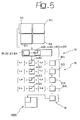
- FIG. 5 shows how the aforesaid operations may be implemented by means of appropriate matrix sums and multiplications, remaining in the DCT domain.
- the solution according to the invention is therefore suited to being implemented ⁇ according to criteria that are within the reach of a person skilled in the branch on the basis of the detailed description of the invention provided herein ⁇ whether by using a specialized processor or by using a general-purpose digital computer (such as a digital signal processor ⁇ DSP) on which the computer program product according to the invention is run.
- a specialized processor or by using a general-purpose digital computer (such as a digital signal processor ⁇ DSP) on which the computer program product according to the invention is run.
- a general-purpose digital computer such as a digital signal processor ⁇ DSP
- Figure 5 considers a single macroblock MB of the four that are usually to be reduced simultaneously.
- Each 8x8 DCT block B1, B2, B3 and B4 deriving from the macroblock MB is processed in such a way as to preserve only the coefficients corresponding to the microblock mB1, mB2, mB3, mB4 in the top left-hand corner.
- microblock mB1, mB2, mB3, mB4 is then multiplied by appropriate matrices, on the right and on the left, according to the position of the block.
- All the matrices considered are of size 8x8 (hence of a rank higher than, namely twice, that of the microblocks to which they are applied) and, in the diagram of Figure 5, they are respectively designated by S tl, D_tl, S_tr, D_tr, S_bl, D_bl, S_br, D_br, where S stands for Sinister (left), D stands for Dexter (right), t stands for top, b stands for bottom, 1 stands for left, and r stands for right.
- Figure 6 which is divided into three parts designated by a), b) and c), represents three masking structures (with reference of course to a 4x4 microblock) which, once applied to the microblocks on the top left mB1, mB2, mB3, mB4 isolated from the blocks B1 B2, B3, B4, have yielded particularly satisfactory results from the qualitative standpoint. And this, even though the aforesaid masking action entails, in itself, setting to zero the other coefficients of the microblock, namely the coefficients corresponding to the positions appearing in white in the various masks M1, M2 and M3. It will, however, be appreciated that the masks illustrated in Figure 6 are in any case such as to preserve the components that are closest to the d.c. coefficient (DC).
- DC d.c. coefficient
Landscapes
- Engineering & Computer Science (AREA)
- Multimedia (AREA)
- Signal Processing (AREA)
- Compression Or Coding Systems Of Tv Signals (AREA)
- Compression, Expansion, Code Conversion, And Decoders (AREA)
- Compression Of Band Width Or Redundancy In Fax (AREA)
Abstract
Description
- The present invention relates to the processing of bitstreams encoded according to the MPEG standard.
- The MPEG (Moving Pictures Experts Group) standard proposes a set of algorithms dedicated to the compression of sequences of digital (audio/video) signals. The techniques used are based on the reduction in spatial and temporal redundancy of the sequence.
- According to the MPEG standard, reduction in spatial redundancy is obtained by independently compressing the individual images, using a discrete cosine transform (DCT), quantization and Huffman coding.
- Reduction in temporal redundancy is obtained by exploiting the correlation that exists between successive and/or temporally close images in the sequence. Approximately, it is assumed that each portion of an image could be expressed locally as the translation of a portion of a previous and/or subsequent image in the sequence.
- The foregoing corresponds to criteria that are well known to the prior art and hence are such as not to require further illustration herein.
- In the actual use of the MPEG standard it is possible to transmit (or record) films, or in general video sequences, on a variety of channels and media, each of which has its own characteristics of capacity, speed and cost.
- The transmission of a film (or of a video program in general) starting from the master recording may be done, for instance, on DVD media, via satellite, radio antenna, cable, and ― to an ever-increasing extent ― via telematic networks, such as Internet, and/or to mobile terminals, such as UMTS mobile terminals.
- In order to make available a wide range of the aforementioned transmission modalities and to expand it even further, it is necessary to be able to adapt the characteristics of the MPEG bitstream to the transmission/storage channel, as well as to the characteristics of the display units employed to display the corresponding images.
- The foregoing entails, among other things, the need to convert the format of an MPEG video bitstream in such a way that the resulting sequence is reduced, for example, to one quarter of the original format.
- In order to obtain the above result, it is possible, for example, to apply the "canonical" solution represented in Figure 1.
- In the case of Figure 1, an input MPEG video bitstream, designated by IS, is entered into a
decoder 100, which is able to read and decode the bitstream IS with a format corresponding to a number of pixels Hor x Vert per image. - The signal thus decoded is fed to a set of
downsampling filters 120 which are able to downsample the image starting from the original format Hor x Vert to a reduced format (Hor/N) x (Vert/M). - The signal thus subjected to conversion of format is entered into an
encoder 140, which is able to generate a syntax in compliance with the MPEG standard, in view of its being sent on to a transmission/storage channel C and received in adecoder 160. - The
decoder 160 is able to read and decode an MPEG bitstream with a number of pixels (Hor/N) x (Vert/M) per image, hence one with a reduced format, generating at output a corresponding video sequence OS. - The above technique in effect entails a conversion of the original MPEG bitstream (irrespective of whether this is in compliance with the MPEG2 specification or with the MPEG4 specification) into decoded images that are a sequence of frames. The change of resolution is based upon a filtering action ― this being preferably a finite-impulse-response (FIR) filtering ― which is able to bring about a conversion based upon the availability of a certain number of pixels for each component of luminance and chrominance of the image. The pixels in question are multiplied by appropriate weights, and the results are accumulated and divided by the sum of said weights.
- Certain pixels are not transmitted in the resulting image, depending upon the factor of change of resolution chosen. For this reason, starting from a bitstream decoded with an arbitrary bitrate B1 it is always possible to obtain a bitstream of bitrate B2 by simply connecting the output of the decoder to the input of the change-of-resolution block. The output of the latter is then connected to the input of the decoder, which can be programmed in such a way as to encode the signal at bitrate B2 and then transmit it to the decoder.
- The above solution, which may be defined as an explicit transcoding, presents the fundamental drawback due to the computational complexity linked to its implementation, a computation complexity which renders the solution in question far from attractive in general and in any case unacceptable in those applicational contexts in which a sufficient processing capacity is not available.
- A solution that is alternative to the canonical approach examined previously is described in the European patent applications Nos. 01830084.8 and 01830227.3, both in the name of the present applicant.
- The above alternative solution is based upon a "transcoding" process which makes it possible to convert the format, i.e., change the resolution, by operating in the domain of the discrete cosine transform (DCT) of the prediction error. In this way, it is possible to reduce considerably the computational complexity of the operation of format conversion, thus reducing accordingly the implementational complexity.
- In order to achieve a correct anti-aliasing filtering function, it is in any case necessary to resort to linear-filtering techniques, which require, as is known from the theory of digital filtering, the availability of a certain number of coefficients surrounding the ones that are being processed, the aim being to eliminate, or at least reduce as far as possible, edge effects.
- The purpose of the present invention is to provide a solution for conversion of format implemented operating in the DCT domain that is able to overcome the intrinsic constraint of the known solutions referred to previously.
- According to the present invention, the above purpose is achieved thanks to a process having the characteristics specified to in the annexed claims.
- The invention also relates to the corresponding system, as well as to the corresponding computer program product which can be loaded directly into the memory of a digital computer and which comprises portions of software code which are adapted to perform the process according to the invention when the computer program product is run on a digital computer.
- The solution according to the invention makes it possible to obtain, in the discrete cosine transform (DCT) domain, block downsampling of an MPEG video bitstream in such a way that the resulting sequence is reduced, for example, to one quarter of the original format.
- The solution according to the invention is characterized by its ease of implementation and by the corresponding reduction in computational complexity and in the resulting expenditure of storage space, without this being in any way prejudicial to the quality of the final result.
- The solution according to the invention is therefore proposed as an alternative solution both with respect to frequency conversion performed in the pixel domain by means of FIR pre-filtering and decimation, and with respect to the implementation by means of filtering in the DCT domain.
- In order to achieve the above purpose, obtaining results that are superior or at least equivalent to those of the solutions according to the prior art, the solution according to the invention adopts a non-linear technique for anti-aliasing filtering.
- The invention will now be described, purely by way of non-limiting example, with reference to the annexed drawings, in which:
- Figure 1, which regards the prior art, has already been described previously;
- Figures 2 and 3 are schematic illustrations of the organization of the macroblocks and of the corresponding blocks in the framework of the MPEG standard, as well as of the definition of corresponding microblocks according to the invention;
- Figure 4 illustrates the basic principle of the selection operation performed in the solution according to the invention;
- Figure 5 is a functional block diagram illustrating the processing operations performed in the framework of a system according to the invention;
- Figure 6 illustrates a few examples of masking structures that may be used in the context of the present invention; and
- Figure 7 is essentially a diagram that synthesizes the principles underlying the invention.
- As has already been said previously, the conversion of format of a video signal usually involves anti-aliasing low-pass filtering and subsequent decimation of the filtered pixels.
- Operating in the DCT domain, which is typical of the MPEG standard, the blocks of pixels (usually of size 8x8) are broken down into the equivalent spatial sequences in order to reduce the number of representative coefficients (which may vary according to the bitrate).
- In this way the visibility of the individual pixels is lost, and consequently the low-pass filtering and decimation are carried out on the individual frequencies.
- The variance of the DCT coefficients, and hence their variability, decreases very rapidly with the frequencies. In order to reconstruct an image, it is sufficient to preserve only a relatively small set of terms concentrated around the d.c. coefficient (DC). In addition, it is known that the human eye is less sensitive to high frequencies than to low frequencies, and this implies that minor errors resulting from the elimination of the high frequencies end up not having any particular importance of a subjective nature.
- In the MPEG standard, the 8x8 DCT blocks are grouped together in sets of four in such a way as to give rise to 16x16 macroblocks. Figure 2 illustrates a macroblock MB which groups together four blocks B1, B2, B3 and B4.
- Reducing to one quarter the format of a video bitstream means reducing to one quarter each macroblock, i.e., passing from macroblocks to blocks.
- In the final bitstream, the blocks obtained from downsampling are re-organized into 16x16 macroblocks. The overall number of macroblocks is hence reduced to one quarter between the input bitstream and the output bitstream.
- The solution according to the invention envisages, in its currently preferred embodiment, performing the anti-aliasing filtering by exploiting a non-linear approach that chooses the frequencies of the source image that are to be preserved, eliminating the other frequencies. Eliminating a DCT coefficient means removing the energy corresponding to a given spatial sequential component (vertical, horizontal, vertical plus horizontal).
- The low-pass filtering and decimation operations performed are thus organized into two steps.
- The first step basically consists in identifying and preserving the frequencies that are deemed to be significant, eliminating the remaining frequencies. The said selection is carried out within each block B1, B2, B3 and B4 by means of a DCT-coefficient visibility mask applied to a 4x4 "microblock" and setting to zero the coefficients of the other three microblocks.
- Figure 3 represents a generic block Bi, and the microblock selected, which is designated by mBi, is the one illustrated on the top left. The coefficients of the other three microblocks which occupy the positions on the bottom left, top right and bottom right are, instead, set to zero.
- The second step basically consists of a decimation obtained by performing, on the microblock mB previously isolated, the inverse discrete cosine transform (IDCT), which is thus calculated on sixteen coefficients (4x4), and by performing division by an appropriate distortion factor. The IDCT applied to the 4x4 microblock makes it possible to shape further the dark-band spectrum wherever a higher degree of attenuation is encountered. The IDCT is repeated on the microblocks of the four blocks that are to be merged. The four microblocks resulting from the IDCT are gathered together in an 8x8 block to which the DCT is applied.
- The above operating sequence is schematically illustrated in the functional flowchart represented in Figure 4.
- In Figure 4, MB designates the individual macroblock (this will generally be the i-th block in a video sequence) which is to be divided, in a step designated by 10, into four 8x8 blocks designated by B1 B2, B3 and B4.
- In a step designated by 12, from each of the blocks B1, B2, B3, B4 a corresponding microblock mB1, mB2, mB3, mB4 is derived. This is done by selecting the 4x4 microblock on the top left ― hence the one located in a position close to the d.c. component ― according to the modalities described previously, namely setting to zero the coefficients of the other microblocks.
- The steps designated by 14 and 16 respectively correspond to a possible masking action performed on each microblock mB1, mB2, mB3, mB4 (this may be done by means of masks, such as the masks M1, M2 or M3 which are illustrated in Figure 6 and which will be described in greater detail hereinafter) and to execution of the IDCT on the microblocks mB1, mB2, mB3, mB4, after possible prior masking.
- The
reference number 18 designates the merging of the microblocks thus obtained into a single 8x8 block which, in the step designated by 20, is to undergo the DCT operation with a view to obtaining the final decimated block, designated by MBD. - The diagram of Figure 5 shows how the aforesaid operations may be implemented by means of appropriate matrix sums and multiplications, remaining in the DCT domain.
- The solution according to the invention is therefore suited to being implemented ― according to criteria that are within the reach of a person skilled in the branch on the basis of the detailed description of the invention provided herein ― whether by using a specialized processor or by using a general-purpose digital computer (such as a digital signal processor ― DSP) on which the computer program product according to the invention is run.
- In particular, Figure 5 considers a single macroblock MB of the four that are usually to be reduced simultaneously. Each 8x8 DCT block B1, B2, B3 and B4 deriving from the macroblock MB is processed in such a way as to preserve only the coefficients corresponding to the microblock mB1, mB2, mB3, mB4 in the top left-hand corner.
- The microblock mB1, mB2, mB3, mB4 is then multiplied by appropriate matrices, on the right and on the left, according to the position of the block. All the matrices considered are of size 8x8 (hence of a rank higher than, namely twice, that of the microblocks to which they are applied) and, in the diagram of Figure 5, they are respectively designated by S tl, D_tl, S_tr, D_tr, S_bl, D_bl, S_br, D_br, where S stands for Sinister (left), D stands for Dexter (right), t stands for top, b stands for bottom, 1 stands for left, and r stands for right.
- Four blocks are thus obtained, designated by B1t, B2t, B3t, B4t (temporary i-th blocks), the sum of which, designated by B1f, corresponds to the merging block of
step 18 of Figure 4 which has already undergone DCT (step 20 of Figure 4). In this way it is possible to calculate the IDCT applying the calculation to the 4x4 microblocks (instead of the 8x8 blocks as would normally be the case), then performing the merging and the DCT of the resulting 8x8 block. - Figure 6, which is divided into three parts designated by a), b) and c), represents three masking structures (with reference of course to a 4x4 microblock) which, once applied to the microblocks on the top left mB1, mB2, mB3, mB4 isolated from the blocks B1 B2, B3, B4, have yielded particularly satisfactory results from the qualitative standpoint. And this, even though the aforesaid masking action entails, in itself, setting to zero the other coefficients of the microblock, namely the coefficients corresponding to the positions appearing in white in the various masks M1, M2 and M3. It will, however, be appreciated that the masks illustrated in Figure 6 are in any case such as to preserve the components that are closest to the d.c. coefficient (DC).
- Of course, the solution described is not limited, as regards its possible applications, to the case alone of microblocks of size corresponding to 4x4 pixels (hence for a reduction to one quarter of the original spatial resolution), but may be generalized to arbitrary sizes of said microblocks.
- In particular, with reference to the schematic representation of Figure 7, it is possible to extract, from each block under examination belonging to a given macroblock (whatever the sizes of said macroblocks and said blocks), a microblock of arbitrary size MxN, provided that this size is smaller than that of the complete block. To each microblock it is then possible to apply the inverse discrete cosine transform IDCTMxN, finally proceeding to a reconstruction operation, generically designated by R, where a block of the same size as the original one is reconstructed.
- Of course, without prejudice to the principle of the invention, the details of implementation and the embodiments may vary widely with respect to what is described and illustrated herein, without thereby departing from the scope of the present invention as defined in the annexed claims.
Claims (14)
- A process for converting the format of MPEG video bitstreams, characterized in that it comprises the operations of:identifying DCT macroblocks (MB) comprised in said bitstreams, each macroblock comprising a plurality of blocks (B1, B2, B3, B4);dividing (10) each of said macroblocks (MB) into respective blocks (B1, B2, B3, B4), each block in turn comprising a plurality of microblocks;identifying and preserving, in each DCT block (B1, B2, B3, B4) comprised in a macroblock (MB), the significant frequencies, isolating (12) a corresponding microblock (mB1, mB2, mB3, mB4) of said block (B1, B2, B3, B4) ;performing (16) an inverse discrete cosine transform (16) on the isolated microblock (mB1, mB2, mB3, mB4);gathering (18) said microblock, which has been isolated and subjected to an inverse discrete cosine transform, together with the homologous microblocks obtained from the other DCT blocks comprised in a respective macroblock (MB), so as to obtain a merging block; andapplying to said merging block the discrete cosine transform (20) so as to obtain a final block that can be assembled into a macroblock (MBD) with converted format.
- The process according to Claim 1, characterized in that it comprises the operation of identifying said DCT macroblocks (MB) as 16x16 macroblocks.
- The process according to Claim 1 or Claim 2, characterized in that it comprises the operation of dividing said macroblocks (MB) into 8x8 DCT blocks (B1, B2, B3, B4).
- The process according to any one of the preceding claims, characterized in that it comprises the operation of selecting said corresponding microblock (mB1, mB2, mB3, mB4) as a 4x4 microblock.
- The process according to any one of the preceding claims, characterized in that said corresponding microblock (mB1, mB2, mB3, mB4) is chosen in the area around the d.c. component of the respective block (B1 B2, B3, B4).
- The process according to any one of the preceding claims, characterized in that said corresponding microblock (mB1, mB2, mB3, mB4) is identified as the microblock on the top left-hand side of the respective block (B1, B2, B3, B4).
- The process according to any one of the preceding claims, characterized in that said operations of performing, on the isolated microblock (mB1, mB2, mB3, mB4), an inverse cosine discrete transform (16), gathering (18) said microblock, which has been isolated and subjected to an inverse discrete cosine transform, with the homologous microblocks obtained from the other DCT blocks comprised in a respective macroblock (MB), and applying to said merging block the discrete cosine transform (20) are carried out multiplying said isolated microblock and said homologous microblocks (mB1, mB2, mB3, mB4) by respective multiplication matrices (S_tl, D_tl, S_tr, D_tr, S_bl, D_bl, S_br, D_br) so as to obtain respective temporary blocks (B1t, B2t, B3t, B4t) and adding together said respective temporary blocks (B1t, B2t, B3t, B4t), the sum of said temporary blocks identifying said final block that can be assembled into a macroblock (MBD) with converted format.
- The process according to Claim 8, characterized in that said multiplication matrices (S_tl, D_tl, S_tr, D_tr, S_bl, D_bl, S_br, D_br) are of a rank higher than, and preferably twice, that of said isolated microblock and said homologous microblocks (mB1, mB2, mB3, mB4).
- The process according to any one of the preceding claims, characterized in that it comprises the operation of subjecting said corresponding microblock (mB1, mB2, mB3, mB4) to masking, using a mask (M1, M2, M3) that acts on a subset of the microblock (mB1, mB2, mB3, mB4) itself.
- The process according to any one of the preceding claims, characterized in that said operation of isolating said corresponding microblock (mB1, mB2, mB3, mB4) involves setting to zero the coefficients associated to the microblocks of said block (B1, B2, B3, B4) other than said corresponding microblock (mB1, mB2, mB3, mB4).
- The process according to any one of the preceding claims, characterized in that said inverse discrete cosine transform (IDCT) is calculated on sixteen coefficients.
- The process according to any one of the preceding claims, characterized in that it comprises the operation of applying a distortion factor to the result of said inverse discrete cosine transform (IDCT).
- A system for converting the format of an MPEG video bitstream, in the form of a dedicated computer circuit operating according to the process as per any one of Claims 1 to 12.
- A computer program product directly loadable into the memory of a digital computer and comprising software code portions for performing the operations according to any one of Claims 1 to 12 when said product is run on a computer.
Priority Applications (3)
| Application Number | Priority Date | Filing Date | Title |
|---|---|---|---|
| EP01830589A EP1294195A1 (en) | 2001-09-14 | 2001-09-14 | A process for the format conversion of MPEG bitstreams, a system and computer program product therefor |
| JP2002261167A JP2003163932A (en) | 2001-09-14 | 2002-09-06 | MPEG bitstream format conversion method, system and computer program product therefor |
| US10/243,081 US7369613B2 (en) | 2001-09-14 | 2002-09-12 | Process for the format conversion of MPEG bitstreams, a system and computer program product therefor |
Applications Claiming Priority (1)
| Application Number | Priority Date | Filing Date | Title |
|---|---|---|---|
| EP01830589A EP1294195A1 (en) | 2001-09-14 | 2001-09-14 | A process for the format conversion of MPEG bitstreams, a system and computer program product therefor |
Publications (1)
| Publication Number | Publication Date |
|---|---|
| EP1294195A1 true EP1294195A1 (en) | 2003-03-19 |
Family
ID=8184692
Family Applications (1)
| Application Number | Title | Priority Date | Filing Date |
|---|---|---|---|
| EP01830589A Withdrawn EP1294195A1 (en) | 2001-09-14 | 2001-09-14 | A process for the format conversion of MPEG bitstreams, a system and computer program product therefor |
Country Status (3)
| Country | Link |
|---|---|
| US (1) | US7369613B2 (en) |
| EP (1) | EP1294195A1 (en) |
| JP (1) | JP2003163932A (en) |
Families Citing this family (4)
| Publication number | Priority date | Publication date | Assignee | Title |
|---|---|---|---|---|
| US7735111B2 (en) * | 2005-04-29 | 2010-06-08 | The Directv Group, Inc. | Merging of multiple encoded audio-video streams into one program with source clock frequency locked and encoder clock synchronized |
| US20140327737A1 (en) * | 2013-05-01 | 2014-11-06 | Raymond John Westwater | Method and Apparatus to Perform Optimal Visually-Weighed Quantization of Time-Varying Visual Sequences in Transform Space |
| FR3016764B1 (en) * | 2014-01-17 | 2016-02-26 | Sagemcom Broadband Sas | METHOD AND DEVICE FOR TRANSCODING VIDEO DATA FROM H.264 TO H.265 |
| US10893266B2 (en) * | 2014-10-07 | 2021-01-12 | Disney Enterprises, Inc. | Method and system for optimizing bitrate selection |
Citations (2)
| Publication number | Priority date | Publication date | Assignee | Title |
|---|---|---|---|---|
| WO2000000907A1 (en) * | 1998-06-26 | 2000-01-06 | Telefonaktiebolaget Lm Ericsson (Publ) | Efficient down-scaling of dct compressed images |
| WO2000051357A1 (en) * | 1999-02-25 | 2000-08-31 | Sarnoff Corporation | Transcoding between different dct-based image compression standards |
Family Cites Families (9)
| Publication number | Priority date | Publication date | Assignee | Title |
|---|---|---|---|---|
| US5262854A (en) * | 1992-02-21 | 1993-11-16 | Rca Thomson Licensing Corporation | Lower resolution HDTV receivers |
| US6434275B1 (en) * | 1997-05-28 | 2002-08-13 | Sony Corporation | Block distortion reduction method and device and encoding method and device |
| US6895091B1 (en) * | 2000-07-07 | 2005-05-17 | Verizon Corporate Services Group Inc. | Systems and methods for encryption key archival and auditing in a quantum-cryptographic communications network |
| US7471834B2 (en) * | 2000-07-24 | 2008-12-30 | Vmark, Inc. | Rapid production of reduced-size images from compressed video streams |
| US7266148B2 (en) * | 2001-01-05 | 2007-09-04 | Lg Electronics Inc. | Video transcoding apparatus |
| US6873655B2 (en) * | 2001-01-09 | 2005-03-29 | Thomson Licensing A.A. | Codec system and method for spatially scalable video data |
| US6671322B2 (en) * | 2001-05-11 | 2003-12-30 | Mitsubishi Electric Research Laboratories, Inc. | Video transcoder with spatial resolution reduction |
| US7028059B2 (en) * | 2002-06-24 | 2006-04-11 | Sun Microsystems, Inc. | Apparatus and method for random number generation |
| US7298925B2 (en) * | 2003-09-30 | 2007-11-20 | International Business Machines Corporation | Efficient scaling in transform domain |
-
2001
- 2001-09-14 EP EP01830589A patent/EP1294195A1/en not_active Withdrawn
-
2002
- 2002-09-06 JP JP2002261167A patent/JP2003163932A/en active Pending
- 2002-09-12 US US10/243,081 patent/US7369613B2/en active Active
Patent Citations (2)
| Publication number | Priority date | Publication date | Assignee | Title |
|---|---|---|---|---|
| WO2000000907A1 (en) * | 1998-06-26 | 2000-01-06 | Telefonaktiebolaget Lm Ericsson (Publ) | Efficient down-scaling of dct compressed images |
| WO2000051357A1 (en) * | 1999-02-25 | 2000-08-31 | Sarnoff Corporation | Transcoding between different dct-based image compression standards |
Non-Patent Citations (3)
| Title |
|---|
| DUGAD R ET AL: "A fast scheme for image size change in the compressed domain", IEEE TRANSACTIONS ON CIRCUITS AND SYSTEMS FOR VIDEO TECHNOLOGY, APRIL 2001, IEEE, USA, vol. 11, no. 4, pages 461 - 474, XP002192206, ISSN: 1051-8215 * |
| KIM D ET AL: "TRANSCODING DV INTO MPEG-2 IN THE DCT DOMAIN", PROCEEDINGS OF THE SPIE, SPIE, BELLINGHAM, VA, US, vol. 3653, no. 1/2, 1998, pages 1026 - 1032, XP000870210 * |
| MERHAV N ET AL: "FAST ALGORITHMS FOR DCT-DOMAIN IMAGE DOWN-SAMPLING AND FOR INVERSE MOTION COMPENSATION", IEEE TRANSACTIONS ON CIRCUITS AND SYSTEMS FOR VIDEO TECHNOLOGY, IEEE INC. NEW YORK, US, vol. 7, no. 3, 1 June 1997 (1997-06-01), pages 468 - 476, XP000690585, ISSN: 1051-8215 * |
Also Published As
| Publication number | Publication date |
|---|---|
| US20030090591A1 (en) | 2003-05-15 |
| US7369613B2 (en) | 2008-05-06 |
| JP2003163932A (en) | 2003-06-06 |
Similar Documents
| Publication | Publication Date | Title |
|---|---|---|
| EP0771507B1 (en) | Method and apparatus for reduction of image data compression noise | |
| US7010041B2 (en) | Process for changing the syntax, resolution and bitrate of MPEG bitstreams, a system and a computer product therefor | |
| KR100253931B1 (en) | Method and apparatus for decoding digital image sequence | |
| US5796434A (en) | System and method for performing motion estimation in the DCT domain with improved efficiency | |
| EP2141927A1 (en) | Filters for video coding | |
| JP4319352B2 (en) | Scaling compressed image | |
| US5675666A (en) | Image data compression method and apparatus with pre-processing to compensate for the blocky effect | |
| EP0666695A2 (en) | Adaptive spatial-temporal postprocessing for low bit-rate coded image sequences | |
| EP0854653A2 (en) | Fast inverse discrete cosine transform system and method and video compression/decompression system | |
| EP0577350B1 (en) | A video signal coding and decoding apparatus with an adaptive edge enhancement filter | |
| JPH1175186A (en) | Scaled forward and backward discrete cosine transform and video compression and decompression system using it | |
| JP4382284B2 (en) | Subband encoding / decoding | |
| KR20010093772A (en) | Dct domain down conversion system that compensates for idct mismatch | |
| US7242717B2 (en) | Wavelet domain motion compensation system | |
| KR100229796B1 (en) | Image decoding system with compensation function for degraded image | |
| JPH08289294A (en) | Animation image compression system by adaptive quantization | |
| US6160920A (en) | Cosine transforming and quantizing device, method of reducing multiplication operations in a video compressing apparatus | |
| EP1511319A1 (en) | Film Grain Extraction Filter | |
| US7369613B2 (en) | Process for the format conversion of MPEG bitstreams, a system and computer program product therefor | |
| JPH08294119A (en) | Image coding / decoding device | |
| KR100386639B1 (en) | Method for decompression of images and video using regularized dequantizer | |
| EP1231794A1 (en) | A process for changing the resolution of MPEG bitstreams, a system and a computer program product therefor | |
| JPH08191444A (en) | Video signal decoding device | |
| JPH05344492A (en) | Interframe predictive coding | |
| CN116546295A (en) | A video shooting processing method and system |
Legal Events
| Date | Code | Title | Description |
|---|---|---|---|
| PUAI | Public reference made under article 153(3) epc to a published international application that has entered the european phase |
Free format text: ORIGINAL CODE: 0009012 |
|
| AK | Designated contracting states |
Kind code of ref document: A1 Designated state(s): AT BE CH CY DE DK ES FI FR GB GR IE IT LI LU MC NL PT SE TR Designated state(s): AT BE CH CY DE DK ES FI FR GB GR IE IT LI LU MC NL PT SE TR |
|
| AX | Request for extension of the european patent |
Extension state: AL LT LV MK RO SI |
|
| 17P | Request for examination filed |
Effective date: 20030519 |
|
| AKX | Designation fees paid |
Designated state(s): DE FR GB IT |
|
| 17Q | First examination report despatched |
Effective date: 20080627 |
|
| STAA | Information on the status of an ep patent application or granted ep patent |
Free format text: STATUS: THE APPLICATION HAS BEEN WITHDRAWN |
|
| 18W | Application withdrawn |
Effective date: 20090925 |