EP1294176A2 - Image data processing method for ink jet printer - Google Patents
Image data processing method for ink jet printer Download PDFInfo
- Publication number
- EP1294176A2 EP1294176A2 EP02256222A EP02256222A EP1294176A2 EP 1294176 A2 EP1294176 A2 EP 1294176A2 EP 02256222 A EP02256222 A EP 02256222A EP 02256222 A EP02256222 A EP 02256222A EP 1294176 A2 EP1294176 A2 EP 1294176A2
- Authority
- EP
- European Patent Office
- Prior art keywords
- ink
- image data
- color
- processing method
- data processing
- Prior art date
- Legal status (The legal status is an assumption and is not a legal conclusion. Google has not performed a legal analysis and makes no representation as to the accuracy of the status listed.)
- Granted
Links
- 238000003672 processing method Methods 0.000 title claims abstract description 21
- 238000013139 quantization Methods 0.000 claims abstract description 15
- 238000007641 inkjet printing Methods 0.000 claims abstract description 14
- 238000009792 diffusion process Methods 0.000 claims description 27
- 238000010521 absorption reaction Methods 0.000 claims description 5
- 239000000976 ink Substances 0.000 description 103
- 239000003086 colorant Substances 0.000 description 11
- 238000004364 calculation method Methods 0.000 description 7
- 238000005516 engineering process Methods 0.000 description 4
- 230000007246 mechanism Effects 0.000 description 4
- 238000010586 diagram Methods 0.000 description 3
- 230000000873 masking effect Effects 0.000 description 3
- 238000000034 method Methods 0.000 description 3
- 238000006243 chemical reaction Methods 0.000 description 2
- 230000002093 peripheral effect Effects 0.000 description 2
- 239000011347 resin Substances 0.000 description 2
- 229920005989 resin Polymers 0.000 description 2
- 230000007423 decrease Effects 0.000 description 1
- 239000000463 material Substances 0.000 description 1
- 230000007723 transport mechanism Effects 0.000 description 1
Images



Classifications
-
- H—ELECTRICITY
- H04—ELECTRIC COMMUNICATION TECHNIQUE
- H04N—PICTORIAL COMMUNICATION, e.g. TELEVISION
- H04N1/00—Scanning, transmission or reproduction of documents or the like, e.g. facsimile transmission; Details thereof
- H04N1/46—Colour picture communication systems
- H04N1/52—Circuits or arrangements for halftone screening
-
- H—ELECTRICITY
- H04—ELECTRIC COMMUNICATION TECHNIQUE
- H04N—PICTORIAL COMMUNICATION, e.g. TELEVISION
- H04N1/00—Scanning, transmission or reproduction of documents or the like, e.g. facsimile transmission; Details thereof
- H04N1/40—Picture signal circuits
- H04N1/40087—Multi-toning, i.e. converting a continuous-tone signal for reproduction with more than two discrete brightnesses or optical densities, e.g. dots of grey and black inks on white paper
Definitions
- This invention relates to an image data processing method, and in particular, to an image data processing method suitable to an ink jet printer.
- FIG. 5 is a drawing showing a relationship between gradation and spatial ink density in the case where inks of two colors, a deep color and a pale color, are used.
- This invention has been made in view of the above-mentioned problems of conventional technologies, and it is its object to provide an image data processing method for an ink jet printer having a simple structure and being capable of suppressing ink overflow.
- An image data processing method for ink jet printer of this invention comprises the steps of obtaining an allowable amount of ink in accordance with inputted image data and the characteristic of a medium for forming an image, selecting an ink jetting domain on the basis of said allowable amount of ink, while fixing the amount of ink in said selected ink jetting domain at a specified value, and practicing a quantization processing with the amount of ink in said ink jetting domain fixed at the specified value.
- an ink jetting domain where the amount of ink is determined to be a specified value (a low value or zero) is forcibly formed.
- the color error produced by forcibly forming a domain where the amount of ink is determined to be a specified value is canceled by adjusting the color in the neighboring domains by a quantization processing such as an error diffusion processing, by which a high-quality image can be formed with a simple structure, while ink overflow is suppressed.
- Fig. 1 is a drawing showing ink jetting domains on a medium schematically.
- positions indicated by a circle are ink landing (jetting) domains.
- the zone A1 enclosed by the dotted line is composed of 9 ink landing domains, and in the case where ink overflow in zone A1 is surmised from the inputted image data and the characteristics of the medium for forming an image, the amount of ink jetting for the central ink landing domain A2 is made to be a specified value, for example, zero.
- the domain A2 absorbs the overflow; therefore, as the result, ink overflow can be suppressed.
- the amount of ink of the domain A2 is made zero, the color of the domain A2 is recognized as the color of the medium (generally speaking, white), and if any control is not made, the image color of the zone A1 is reduced to a whitish color. Therefore, such a color error is canceled by making ink drops having a deeper color land on the ink landing domains around the zone A2.
- the degree of making the ink color deep can be obtained, for example, by an error diffusion processing, but it is not limited to this. Because the ink landing domains are extremely minute, when it is viewed from a distant position, the color of the zone A1 appears approximately the same as that of the original image; hence, the image quality can be preserved.
- the aforesaid processing to fix the amount of ink at a specified value is determined in accordance with the kinds of the ink color to be used for expressing the color corresponding to the inputted image data. This can be coped with by changing the characteristic of the noise and/or the characteristic of the diffusion filter in the quantization processing in calculating the specified value.
- At least one kind of ink color comprises a pale color and a deep color of the same hue
- this invention can be more effectively applied, because ink overflow tends to occur.
- the aforesaid characteristics of a medium include the ink absorption characteristic of said medium.
- some medium is made of a material which is easy to produce ink overflow.
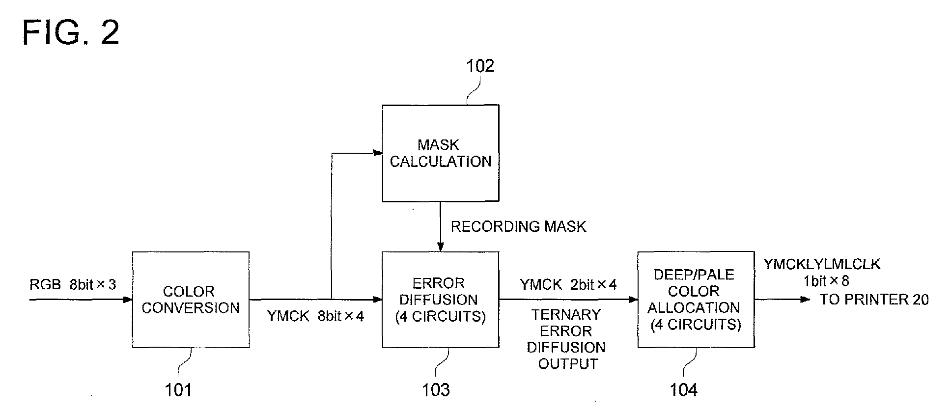
- Fig. 2 and Fig. 3 are drawings showing the outline structure of an image data processing circuit of this invention.
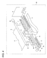
- Fig. 4 is a drawing showing the structure of an ink jet printer.
- a carriage 2 is a case made of resin housing a head 10 and a head driver (not shown in the drawing).
- the head driver (not shown in the drawing) housed in the carriage 2 is composed of an IC for example, and is connected to a control board 9 through a flexible cable 5 which is drawn out of the carriage 2.
- the carriage 2 is moved back and forth alternately in the main scanning direction (X direction) shown by the arrow mark in the drawing by a carriage driving mechanism 6.
- the carriage driving mechanism 6 has a structure including a motor 6a, a pulley 6b, a toothed belt 6c, and a guide rail 6d, and the carriage 2 is fixed to the toothed belt 6c.
- the guide rail 6d consists of two mutually parallel cylindrical-shaped bars and penetrates the through holes of the carriage 2, and the carriage 2 is made to glide on the guide rail.
- the toothed belt 6c is not weighed down with the weight of the carriage 2 itself, and the direction of the alternate motion of the carriage 2 is made to come on a straight line.
- the direction of the moving of the carriage 2 can be changed, and by changing the number of revolutions, also it is possible to change the moving speed of the carriage 2.
- An ink cartridge (not shown in the drawing) has an ink tank inside. The ink supply inlet of the ink tank is opened when the ink cartridge is set to the carriage 2 and connected to an ink supply pipe, and is closed when the connection is released; thus, ink is supplied to the head 10.
- the head 10 On the rear surface of this head 10, ink cartridges containing inks for jetting of deep and pale colors of Y, M, C, and K respectively are arranged in such a way as to be capable of mounting and dismounting. In addition, as regards the ink cartridges, it is omitted to show them in the drawing.
- the flexible cable 5 engages with a data transmitting means and has a structure such that a wiring pattern including a data signal line, power source line, etc. is printed on a flexible film; data are transmitted through it between the carriage 2 and the control board 9, and it complies with the movement of the carriage 2.
- An encoder 7 is made up of a transparent resin film graduated in specified intervals, and by detecting these graduations by means of a photo-sensor provided at the carriage 2, the moving speed, position, and moving direction can be known.
- the paper transport mechanism 8 is a mechanism for transporting a recording paper sheet P in the sub-scanning direction Y indicated by the arrow mark in the drawing, and has a structure comprising a transport motor 8a, a pair of transport rollers 8b, and a pair of transport rollers 8c.
- the transport roller pair 8b and the transport roller pair 8c are roller pairs which are driven by the transport motor 8a and are rotated by a gear train (not shown in the drawing) respectively at peripheral speeds which are approximately equal to each other, with the speed of the transport roller pair 8c made very slightly faster.
- the recording medium P having been conveyed out of a paper feed mechanism (not shown in the drawing), is gripped between the pair of transport rollers 8b which are being rotated at a constant speed, and after its transporting direction is modified to the sub-scanning direction by a paper feed guide (not shown in the drawing), it is gripped by the transport roller pair 8c to be transported.
- the recording medium P passes the recording section without making a bend. Further, the speed of the recording medium P moving in the sub-scanning direction is set at a constant value.
- the carriage 2 is moved at a constant speed in the main scanning direction, and an image is recorded in the specified range on one side of the recording medium P by putting ink drops jetted from the head 10 on it. An image is formed by repeating the above movement.
- image data of 8 bits for each of R, G, and B obtained through photographing by means of a digital still camera, for example, are transformed into data of 8 bits for each of Y, M, C, and K by a color conversion circuit 101, and outputted.
- Such data of 8 bits for each of Y, M, C, and K are supplied into two parts, and one is inputted in a mask calculation circuit 102, while the other is inputted in an error diffusion circuit 103.
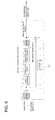
- the error diffusion circuit 103 whose detailed circuit diagram is shown in Fig.
- an error diffusion processing is practiced using a recording mask which has been formed in the mask calculation circuit 102, and the data are converted into data of 2 bits for each of Y, M, C, and K to be outputted. Because an error diffusion processing is a technology known to the public, its detail will not be explained.
- the outputted data of 2 bits for each of Y, M, C, and K are inputted in a deep/pale color allocation circuit 104, where the data are allocated for each of ink kinds, to be transmitted to the printer 20.
- the role of the mask calculating circuit 102 is to obtain recording mask data (that is, the area ratio of ink non-landing domains) by calculating the mask amount from the inputted image data of 8 bits for each of Y, M, C, and K.
- the corresponding values in the inputted image data of 8 bits for each of Y, M, C, and K are masked to be 0, and in that domain, the error diffusion output is also made 0.
- ink amount can be arbitrarily controlled. In this case, even if the deep and pale color inks is subjected to a conventional producing method of ink dots as shown in Table 1, ink amount can be controlled.
- the mask calculation circuit generates recording mask data of appearance frequency proportional to the mask amount by error diffusion.
- the data are converted into the ink amount data for each of the ink kinds in accordance with a deep/pale color allocation rule (102a).
- a deep/pale color allocation rule 102a
- the ink amounts become such ones as shown in Fig. 5(a).
- the total amount of ink is obtained from the ink amount of each color, and the ordinate of the graph is scaled from 0 to 400%.
- the allowable ink amount is obtained by using a calculation equation or a table which has been determined beforehand.
- the values of spatial density of ink is changed in such a way as to be thinned out by multiplying it by 0.8 at the spatial density 200%, and by 0.4 at 400% (processing 102b).
- processing 102b shown in Fig.
- the limiting curve S is constant up to 200%, and it gradually decreases from 200% to 400%, to limit the ink amount.
- the recording frequency (recording mask data) is calculated.
- the error diffusion processing as shown in Fig. 3, noise addition, threshold shift, and quantization processing are performed, and data are fed back by an error filter; however, because these are all known to the public, detailed explanation will be omitted.
- the recording mask data obtained in this way is inputted in the error diffusion circuit 103, if the corresponding pixel (the ink landing domain A1 in Fig. 1) is the object of masking, both the image data and the error diffusion output data are made forcibly to be zero.
- the error diffusion circuit requires only 4 circuits for Y. M. C. and K and one circuit for mask calculation, that is, 5 circuits in total.
- the mask value is made common to all colors; however, it can be considered that, in accordance with the characteristic of human eyes, for example, the ink amount limitation value (102b) is made relatively gentle for higher-density colors (K and C and M) and it is made relatively severe for lower-density colors (Y). Further, also it can be considered that by changing phases of noises to be added for each of the colors (that is, changing the noise characteristics), or by changing the characteristics of the error filters (diffusion filters), the positions of masking are dispersed with the change of color. By changing the masks with color (group), it can be expected to make the fluctuation of luminance distribution smaller.
- the mask amount is calculated through the steps of conversion into the ink amount of each color, addition, and reference to a table of ink amount limit; however, it can be considered a method in which, by using a multi-dimensional LUT for a series of processing steps for example, the ink amount limit value is calculated for each of combinations of image data.
- This example of the embodiment is effective not only for a ternary case but also for a quaternary or an N-ary (N is greater than 4) case in the same way. Further, as compared to the case where data are processed separately for a deep and a pale color, the scale of the circuit can be made smaller.
Landscapes
- Engineering & Computer Science (AREA)
- Multimedia (AREA)
- Signal Processing (AREA)
- Physics & Mathematics (AREA)
- Discrete Mathematics (AREA)
- General Physics & Mathematics (AREA)
- Ink Jet (AREA)
- Record Information Processing For Printing (AREA)
Abstract
Description
| Value of Y (or M, or C, or K) | 0 | 1 | 2 |
| Pale-colored dot (0: not record, 1: record) | 0 | 1 | 0 |
| Deep-colored dot (0: not record, 1: record) | 0 | 0 | 1 |
Claims (14)
- An image data processing method for ink jet printer comprising the steps of:obtaining an allowable amount of ink in accordance with inputted image data and characteristics of a medium for forming an image;selecting an ink jetting domain and fixing the amount of ink in the selected ink jetting domain at a specified value, on the basis of the allowable amount of ink; andpracticing a quantization processing with the amount of ink in the ink jetting domain fixed at the specified value.
- The image data processing method of claim 1, wherein the specified value for the amount of ink in the selected ink jetting domain is zero.
- The image data processing method of claim 1, wherein the quantization processing is an error diffusion processing.
- The image data processing method of claim 2, wherein the quantization processing is an error diffusion processing.
- The image data processing method of claim 1, wherein the allowable amount of ink is determined in accordance with the kind of ink to be used for expressing the color corresponding to the inputted image data.
- The image data processing method of claim 1, wherein the processing to fix the amount of ink at the specified value is determined in accordance with the kind of ink color to be used for expressing the color corresponding to the inputted image data.
- The image data processing method of claim 5, wherein the kind of ink color includes at least cyan, magenta, and yellow.
- The image data processing method of claim 6, wherein the kind of ink color includes at least cyan, magenta, and yellow.
- The image data processing method of claim 7, wherein at least one kind of ink color comprises a pale color and a deep color of the same hue.
- The image data processing method of claim 8, wherein at least one kind of ink color comprises a pale color and a deep color of the same hue.
- The image data processing method of claim 1, wherein the characteristics of a medium include an ink absorption characteristic of the medium.
- The image data processing method of claim 6, wherein a characteristic of a noise in the quantization processing is changed in calculating the specified value in accordance with the color corresponding to the inputted image data.
- The image data processing method of claim 6, wherein a characteristic of a diffusion filter in the quantization processing is changed in calculating the specified value in accordance with the color corresponding to the inputted image data.
- The image data processing method of claim 12, wherein a characteristic of a diffusion filter in the quantization processing is changed in calculating the specified value in accordance with the color corresponding to the inputted image data.
Applications Claiming Priority (2)
| Application Number | Priority Date | Filing Date | Title |
|---|---|---|---|
| JP2001277553 | 2001-09-13 | ||
| JP2001277553A JP4678468B2 (en) | 2001-09-13 | 2001-09-13 | Image data processing method for ink jet printer |
Publications (3)
| Publication Number | Publication Date |
|---|---|
| EP1294176A2 true EP1294176A2 (en) | 2003-03-19 |
| EP1294176A3 EP1294176A3 (en) | 2004-08-04 |
| EP1294176B1 EP1294176B1 (en) | 2007-12-05 |
Family
ID=19102063
Family Applications (1)
| Application Number | Title | Priority Date | Filing Date |
|---|---|---|---|
| EP02256222A Expired - Lifetime EP1294176B1 (en) | 2001-09-13 | 2002-09-09 | Image data processing method for ink jet printer |
Country Status (4)
| Country | Link |
|---|---|
| US (1) | US6698859B2 (en) |
| EP (1) | EP1294176B1 (en) |
| JP (1) | JP4678468B2 (en) |
| DE (1) | DE60223883T2 (en) |
Cited By (1)
| Publication number | Priority date | Publication date | Assignee | Title |
|---|---|---|---|---|
| WO2008075755A1 (en) * | 2006-12-19 | 2008-06-26 | Canon Kabushiki Kaisha | Image processing apparatus, printing apparatus and image processing method |
Families Citing this family (3)
| Publication number | Priority date | Publication date | Assignee | Title |
|---|---|---|---|---|
| EP1790475B1 (en) * | 2004-08-18 | 2017-07-19 | Konica Minolta Medical & Graphic, Inc. | Image recording method and image recording device |
| WO2009031165A1 (en) * | 2007-09-03 | 2009-03-12 | Telecom Italia S.P.A. | Image processing method and apparatus |
| JP6957874B2 (en) * | 2016-12-27 | 2021-11-02 | セイコーエプソン株式会社 | Mobile support device and printing device |
Family Cites Families (9)
| Publication number | Priority date | Publication date | Assignee | Title |
|---|---|---|---|---|
| JP2791066B2 (en) * | 1988-11-15 | 1998-08-27 | キヤノン株式会社 | Recording device |
| JP3031938B2 (en) * | 1990-02-19 | 2000-04-10 | キヤノン株式会社 | Ink jet recording apparatus and image processing method |
| JPH04185354A (en) * | 1990-11-19 | 1992-07-02 | Canon Inc | Image forming device |
| US5485180A (en) * | 1992-08-05 | 1996-01-16 | Hewlett-Packard Company | Inking for color-inkjet printers, using non-integral drop averages, media varying inking, or more than two drops per pixel |
| DE69420225T2 (en) * | 1993-10-18 | 1999-12-09 | Hewlett-Packard Co., Palo Alto | Reduce the number of printed dots in a pixel array |
| JPH10191083A (en) * | 1996-12-27 | 1998-07-21 | Brother Ind Ltd | Color image binarization method and storage medium |
| US6081340A (en) * | 1997-03-31 | 2000-06-27 | Xerox Corporation | Image processing method to reduce marking material coverage with non-linear specifications |
| US6268931B1 (en) * | 1998-02-05 | 2001-07-31 | Canon Kabushiki Kaisha | Density separation for multi-density printing |
| JP3730057B2 (en) * | 1999-07-26 | 2005-12-21 | シャープ株式会社 | Image processing apparatus, image forming apparatus using the same, and recording medium on which program is recorded |
-
2001
- 2001-09-13 JP JP2001277553A patent/JP4678468B2/en not_active Expired - Fee Related
-
2002
- 2002-09-09 DE DE60223883T patent/DE60223883T2/en not_active Expired - Lifetime
- 2002-09-09 EP EP02256222A patent/EP1294176B1/en not_active Expired - Lifetime
- 2002-09-09 US US10/238,353 patent/US6698859B2/en not_active Expired - Fee Related
Cited By (2)
| Publication number | Priority date | Publication date | Assignee | Title |
|---|---|---|---|---|
| WO2008075755A1 (en) * | 2006-12-19 | 2008-06-26 | Canon Kabushiki Kaisha | Image processing apparatus, printing apparatus and image processing method |
| US8154764B2 (en) | 2006-12-19 | 2012-04-10 | Canon Kabushiki Kaisha | Image processing apparatus, printing apparatus and image processing method with generation of binary data according to a correspondence relationship defined by a dot arrangement pattern |
Also Published As
| Publication number | Publication date |
|---|---|
| JP4678468B2 (en) | 2011-04-27 |
| EP1294176B1 (en) | 2007-12-05 |
| US6698859B2 (en) | 2004-03-02 |
| US20030048315A1 (en) | 2003-03-13 |
| JP2003080691A (en) | 2003-03-19 |
| DE60223883T2 (en) | 2008-11-06 |
| DE60223883D1 (en) | 2008-01-17 |
| EP1294176A3 (en) | 2004-08-04 |
Similar Documents
| Publication | Publication Date | Title |
|---|---|---|
| US8514454B2 (en) | Image processing apparatus and method for selecting a processing mode based on number of relative movements of a recording head | |
| US6164747A (en) | Recording apparatus and method of controlling same | |
| DE69328748T2 (en) | Method and device for processing color images | |
| US20060044338A1 (en) | Ink jet printing method and ink jet printing system | |
| EP0369778B1 (en) | Image recording apparatus | |
| US10798266B2 (en) | Image processing apparatus, printing apparatus, and image processing method for performing halftone processing on divided images | |
| US20080123147A1 (en) | Control Of Ink Ejection Amount Based on Dot Formation Order | |
| JP2011083932A (en) | Image processor and image processing method | |
| US8444240B2 (en) | Data generating apparatus, ink-jet printing apparatus, and data generating method | |
| US8998367B2 (en) | Image processing apparatus and image processing method | |
| EP1079327A3 (en) | A printing method and a printing apparatus | |
| JP2009159116A (en) | Image processing device, image recording device, and program | |
| US6760127B1 (en) | Multi-level semi-vector error diffusion | |
| US10005289B2 (en) | Printing apparatus, printing method, and non-transitory computer readable medium for storing program | |
| US6698859B2 (en) | Image data processing method for ink jet printer | |
| US20090059303A1 (en) | Image processing method and printing apparatus | |
| US5933577A (en) | Method and apparatus for processing color images | |
| US9160893B2 (en) | Image recording system and image recording method | |
| US20040246528A1 (en) | Image process apparatus | |
| US7131712B2 (en) | Image recording apparatus | |
| EP0902393A1 (en) | Image processing and thermal transfer printer | |
| JP2011071829A (en) | Dither matrix generation method and computer program | |
| GB2334124A (en) | Printer | |
| US11962737B1 (en) | Edge enhancement with compensation mechanism | |
| US11956403B1 (en) | Edge enhancement with compensation mechanism |
Legal Events
| Date | Code | Title | Description |
|---|---|---|---|
| PUAI | Public reference made under article 153(3) epc to a published international application that has entered the european phase |
Free format text: ORIGINAL CODE: 0009012 |
|
| AK | Designated contracting states |
Kind code of ref document: A2 Designated state(s): AT BE BG CH CY CZ DE DK EE ES FI FR GB GR IE IT LI LU MC NL PT SE SK TR |
|
| AX | Request for extension of the european patent |
Extension state: AL LT LV MK RO SI |
|
| PUAL | Search report despatched |
Free format text: ORIGINAL CODE: 0009013 |
|
| AK | Designated contracting states |
Kind code of ref document: A3 Designated state(s): AT BE BG CH CY CZ DE DK EE ES FI FR GB GR IE IT LI LU MC NL PT SE SK TR |
|
| AX | Request for extension of the european patent |
Extension state: AL LT LV MK RO SI |
|
| 17P | Request for examination filed |
Effective date: 20050117 |
|
| AKX | Designation fees paid |
Designated state(s): DE FR GB |
|
| 17Q | First examination report despatched |
Effective date: 20050330 |
|
| RBV | Designated contracting states (corrected) |
Designated state(s): DE FR GB |
|
| GRAP | Despatch of communication of intention to grant a patent |
Free format text: ORIGINAL CODE: EPIDOSNIGR1 |
|
| GRAS | Grant fee paid |
Free format text: ORIGINAL CODE: EPIDOSNIGR3 |
|
| GRAA | (expected) grant |
Free format text: ORIGINAL CODE: 0009210 |
|
| AK | Designated contracting states |
Kind code of ref document: B1 Designated state(s): DE FR GB |
|
| REG | Reference to a national code |
Ref country code: GB Ref legal event code: FG4D |
|
| REF | Corresponds to: |
Ref document number: 60223883 Country of ref document: DE Date of ref document: 20080117 Kind code of ref document: P |
|
| EN | Fr: translation not filed | ||
| PLBE | No opposition filed within time limit |
Free format text: ORIGINAL CODE: 0009261 |
|
| STAA | Information on the status of an ep patent application or granted ep patent |
Free format text: STATUS: NO OPPOSITION FILED WITHIN TIME LIMIT |
|
| 26N | No opposition filed |
Effective date: 20080908 |
|
| PG25 | Lapsed in a contracting state [announced via postgrant information from national office to epo] |
Ref country code: FR Free format text: LAPSE BECAUSE OF FAILURE TO SUBMIT A TRANSLATION OF THE DESCRIPTION OR TO PAY THE FEE WITHIN THE PRESCRIBED TIME-LIMIT Effective date: 20081003 |
|
| PGFP | Annual fee paid to national office [announced via postgrant information from national office to epo] |
Ref country code: DE Payment date: 20140903 Year of fee payment: 13 |
|
| PGFP | Annual fee paid to national office [announced via postgrant information from national office to epo] |
Ref country code: GB Payment date: 20140903 Year of fee payment: 13 |
|
| REG | Reference to a national code |
Ref country code: DE Ref legal event code: R119 Ref document number: 60223883 Country of ref document: DE |
|
| GBPC | Gb: european patent ceased through non-payment of renewal fee |
Effective date: 20150909 |
|
| PG25 | Lapsed in a contracting state [announced via postgrant information from national office to epo] |
Ref country code: GB Free format text: LAPSE BECAUSE OF NON-PAYMENT OF DUE FEES Effective date: 20150909 Ref country code: DE Free format text: LAPSE BECAUSE OF NON-PAYMENT OF DUE FEES Effective date: 20160401 |