EP1294161A2 - Electronic device - Google Patents
Electronic device Download PDFInfo
- Publication number
- EP1294161A2 EP1294161A2 EP02256387A EP02256387A EP1294161A2 EP 1294161 A2 EP1294161 A2 EP 1294161A2 EP 02256387 A EP02256387 A EP 02256387A EP 02256387 A EP02256387 A EP 02256387A EP 1294161 A2 EP1294161 A2 EP 1294161A2
- Authority
- EP
- European Patent Office
- Prior art keywords
- substrate
- display
- keypad
- electronic device
- wedge shaped
- Prior art date
- Legal status (The legal status is an assumption and is not a legal conclusion. Google has not performed a legal analysis and makes no representation as to the accuracy of the status listed.)
- Granted
Links
Images


Classifications
-
- H—ELECTRICITY
- H04—ELECTRIC COMMUNICATION TECHNIQUE
- H04M—TELEPHONIC COMMUNICATION
- H04M1/00—Substation equipment, e.g. for use by subscribers
- H04M1/02—Constructional features of telephone sets
- H04M1/0202—Portable telephone sets, e.g. cordless phones, mobile phones or bar type handsets
-
- H—ELECTRICITY
- H04—ELECTRIC COMMUNICATION TECHNIQUE
- H04M—TELEPHONIC COMMUNICATION
- H04M1/00—Substation equipment, e.g. for use by subscribers
- H04M1/02—Constructional features of telephone sets
- H04M1/22—Illumination; Arrangements for improving the visibility of characters on dials
-
- H—ELECTRICITY
- H04—ELECTRIC COMMUNICATION TECHNIQUE
- H04M—TELEPHONIC COMMUNICATION
- H04M1/00—Substation equipment, e.g. for use by subscribers
- H04M1/02—Constructional features of telephone sets
- H04M1/0202—Portable telephone sets, e.g. cordless phones, mobile phones or bar type handsets
- H04M1/026—Details of the structure or mounting of specific components
-
- Y—GENERAL TAGGING OF NEW TECHNOLOGICAL DEVELOPMENTS; GENERAL TAGGING OF CROSS-SECTIONAL TECHNOLOGIES SPANNING OVER SEVERAL SECTIONS OF THE IPC; TECHNICAL SUBJECTS COVERED BY FORMER USPC CROSS-REFERENCE ART COLLECTIONS [XRACs] AND DIGESTS
- Y10—TECHNICAL SUBJECTS COVERED BY FORMER USPC
- Y10S—TECHNICAL SUBJECTS COVERED BY FORMER USPC CROSS-REFERENCE ART COLLECTIONS [XRACs] AND DIGESTS
- Y10S345/00—Computer graphics processing and selective visual display systems
- Y10S345/901—Electronic book with display
-
- Y—GENERAL TAGGING OF NEW TECHNOLOGICAL DEVELOPMENTS; GENERAL TAGGING OF CROSS-SECTIONAL TECHNOLOGIES SPANNING OVER SEVERAL SECTIONS OF THE IPC; TECHNICAL SUBJECTS COVERED BY FORMER USPC CROSS-REFERENCE ART COLLECTIONS [XRACs] AND DIGESTS
- Y10—TECHNICAL SUBJECTS COVERED BY FORMER USPC
- Y10S—TECHNICAL SUBJECTS COVERED BY FORMER USPC CROSS-REFERENCE ART COLLECTIONS [XRACs] AND DIGESTS
- Y10S345/00—Computer graphics processing and selective visual display systems
- Y10S345/905—Display device with housing structure
Definitions
- the present invention relates to an electronic device incorporating an electronic display, a keypad and one or more sources of light for illuminating the display and the keypad.
- the electronic device to which this invention relates is a mobile telecommunications device such as a telephone but it could also include any other type of electronic device that incorporates a keypad and an electronic display including, for example, a personal data assistant (PDA) or other electronic device such as a television/stereo remote control unit.
- PDA personal data assistant
- the invention will be described hereinafter in its application to a mobile telephone.
- a conventional mobile telephone includes an electronic display such as an LCD and a keypad.
- the keypad includes a plurality of keys formed on a flexible mat which are accessible through apertures in the front cover of the mobile telephone, and a key pad membrane attached to a substrate beneath the keys.
- the key pad membrane has a pin or other protruberance located beneath each key which deforms a conductive element into contact with a printed circuit board situated beneath the substrate when the key is depressed. An electrical circuit is thereby closed and the selected function is performed.
- One or more light sources such as LED's are located adjacent to the display around its periphery and in the vicinity of the keypad so that the display and the key pad are illuminated when the telephone is in use. At least a portion of each key is formed from a translucent or light transmitting material so that they are visibly illuminated from the front.
- a problem with this known arrangement is that a relatively large number of LED's or other light sources are required between the keys and surrounding the display to ensure that a uniform or homogeneous lighting effect is created over the whole keyboard as well as the display. Furthermore, "hot-spots" or regions of the display and keypad which are illuminated to a greater intensity than other regions are often produced in the immediate vicinity of the light sources. Not only do the LED's and their associated circuitry take up more space within the telephone but its manufacture is more complicated, it is heavier and battery life is reduced due to an increase in power consumption.
- US 4,755,035 discloses a display assembly for an LCD in which the LCD element is mounted on the top surface of a carrier made from light transmitting material.
- a point light source is positioned adjacent to the carrier so that light emitted from the source is transmitted through the carrier to backlight the display.
- the carrier is wedge shaped to ensure uniform backlighting across the LCD.
- US 5,075,824 discloses an LCD/light wedge module in which an LCD is received in a pocket of a wedge shaped carrier.
- the carrier has a pair of openings to receive point light sources so that light emitted from the sources is directed onto the slanted rear surface of the wedge and reflects it towards the LCD so as to provide a more uniform backlighting effect across the LCD.
- the aim of the present invention is to overcome or substantially alleviate the problems with the conventional electronic devices discussed above.
- An electronic device is characterised in that the wedge shaped portion is disposed in a region beneath the keypad such that light emitted by the light source is transmitted through the substrate and is out-coupled from the substrate via the wedge shaped portion to illuminate the keypad.
- the upper surface of the substrate on which the keypad is mounted is substantially planar.
- a portion of the underside of the substrate in a region where the key pad is mounted is inclined at an angle relative to the upper surface to form the wedge shaped portion of the substrate.
- a substantially planar electrical contact sheet is disposed beneath the substrate, a wedge shaped gap being formed between the wedge shaped part of the substrate and the upper surface of the electrical contact sheet.
- the electronic device conveniently includes a retaining member to mount the display on the substrate.
- the upper surface of the electrical contact sheet is preferably covered with a reflective material or coating.
- the electronic device of the invention is a mobile telecommunications device.
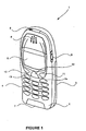
- the preferred electronic device to which this invention is applicable is a mobile telephone such as that illustrated in Figure 1.
- the telephone 1 has a front casing portion 2 and a rear casing portion 3.
- a user interface is provided in the front casing portion 2 and comprises a key pad 4, an electronic display 5, an ear-piece 6, a microphone 7, an on/off key 8 and a scroll key 9 for highlighting a particular item in a menu to enable its selection or for controlling the volume of the sound emitted through the ear-piece 6.
- the telephone 1 is adapted to enable communication via a wireless telecommunications network, e.g. a cellular network. However, the telephone 1 could also be designed for a cordless network.
- the keypad 4 has a first group of keys which are alphanumeric to enable a user to enter a telephone number, write a text message (SMS) or enter a name associated with a particular number, etc.
- the keypad 4 additionally includes five soft keys 10,11,12,13,14.
- the first soft key 10 is used to access the menu structure and to select a function in the menu. Its function changes depending on the status of the telephone 1.
- the second soft key 11 is used to scroll up and down in the display whilst the telephone 1 whilst a menu is displayed. It is also used to access the first entry in the phonebook when the telephone 1 is in a starting position and is ready for use.
- the third soft key 12 is used to enter the phonebook options when the telephone 1 is in the starting position.
- the third soft key 12 is used to close the menu structure or erase entered characters.
- the fourth and fifth soft keys 13,14 are call handling keys.
- the first call handling key 13 is used to start a call or establish a conference call and the second call handling key 14 is used to end a conference call or reject an incoming call.
- FIG 2 shows a schematic representation of the main components of the mobile telephone illustrated in Figure 1.
- the telephone is powered by a removable battery pack 15.
- Signal processing is carried out under the control of a digital microcontroller 16 which has an associated RAM/ROM and flash memory 17.
- Electric analogue signals are produced by microphone 7 and are fed to ear piece 6.
- the controller 16 receives instruction signals from the keypad 4 including the soft keys 10,11,12,13,14 and controls the operation of the display 5. Radio signals are transmitted and received by means of an antenna 23 connected through a radio interface 24 to a codec 25 configured to process signals under control of the controller 16.
- the codec 25 receives analogue signals from the microphone 7, digitises them into a form suitable for transmission and feeds them to the radio interface 24 for transmission through antenna element 23 to the public land mobile network (PLMN). Similarly, received signals are fed to codec 25 so as to produce analogue signals which are fed to the ear piece 6.
- the telephone 1 also includes a subscriber identification module (SIM) card 26, a SIM card reader 27, light emitting diodes (LEDs) 28 and a ringer 29.
- SIM subscriber identification module
- LEDs light emitting diodes
- the individual circuits and elements are of a type well known in the art, for example, in the Nokia range of mobile telephones.
- the display 5 comprises a generally planar module which is mounted to a substantially planar portion of a substrate 30 by a mounting frame 31 which secures the display 5 to the substrate 30.
- a number of raised projections 32 protrude from the peripheral edge of the substrate 30 each of which engage in a co-operating recess 33 in the mounting frame 31.
- the substrate 30 includes an integrally formed region 34 having a substantially planar upper surface 43 to receive the key pad 4 adjacent to the display 5.
- This region 34 has a plurality of apertures 35 (see Figure 4) therein corresponding to the position of each key and a key pad membrane 36 (see Figure 5) is attached over this region 34.
- the key pad membrane 36 may be integrally formed with the key pad 4.
- An electrical contact sheet 37 is disposed beneath the substrate 30 and has a reflective upper surface 38 to reflect light emitted by the LED's 28 toward the substrate 30.
- the electrical contact sheet 37 also has a plurality of resiliently deformable electrically conductive metal domes 39, each dome 39 being positioned beneath a key formed on the key pad 4 and its associated aperture 35 in the substrate 30.
- Each key of the key pad 4 or key pad membrane 36 is provided with a pin (not shown) so that, when a key is depressed, the pin associated with that key passes through its associated aperture 35 in the substrate 30 into contact with a dome 39. Further depression of the key causes that dome 39 to resiliently deform and contact a printed circuit board (not shown) positioned beneath the sheet 37 thereby forming an electrical connection so that the required function is performed.
- the dome 39 When pressure on the key is released, the dome 39 returns to its original non-depressed state due to its resilient nature, thereby terminating the electrical connection.
- the majority of the electronic components including the microphone 7, the ear-piece 6 and the light emitting diodes 28 are mounted on the printed circuit board and are electrically connected thereto.
- the LEDs or other light sources 28 are located on the substrate 30 around the periphery of the display 5 (see Figure 5) so as to illuminate the display 5.
- At least a portion 40 of the underside surface 41 of the substrate 30 in the region 34 that receives the key pad 4 and keypad membrane 36 is formed at an angle relative to its upper, substantially planar surface 43 so that a wedge shaped gap is created between the underside surface 41 of the substrate 30 and the contact sheet 37 in the region 34.
- the substrate 30, which has a substantially planar upper surface 43 is also wedge shaped due to the angled underside surface of the substrate 30, for reasons that will now be explained.
- the wedge shaped part of the substrate 30, or the whole substrate 30, is formed from a light transmitting material so that it acts as a light guide to direct light emitted from the LEDs 28 adjacent to the display 5 toward the key pad 4 so as to illuminate both the key pad 4 and the display 5.
- the intensity of the light out-coupled through the lightguide is more uniform over the whole keypad 4.
- those light rays which meet the interface between the substrate 30 and the surrounding air at a small angle are reflected back rather than being out coupled from the substrate 30. In this way, the light travels through the substrate 30 having been reflected a number of times when incident on the interface between the substrate and the surrounding air.
- the wedge shaped part of the substrate 30 provides the substrate 30 with increased mechanical stability and increases the distance between the substrate 30, the contact sheet 37 and the printed circuit board due to the wedge shaped hollow gap created between the wedge shaped portion of the substrate 30 and the contact sheet 37. This increase in distance reduces the stresses on the printed circuit board caused by heavy key presses such as those which may be made when playing a game or writing a text message on the telephone 1. Also, because the gap is wedge shaped, the keys at one end of the keypad 4 adjacent to the display 5 are positioned further away from the printed circuit board than those at the other end. Therefore, it is preferable to program the keys closest to the display 5 with the game controls so that the stresses produced in the printed circuit board 36 from multiple presses of these keys is minimised.
- the underside of the substrate 30 can be seen more clearly in Figure 4 from which it will be appreciated how, when the contact sheet 37 is put in place, the hollow wedge shaped gap is created between the contact sheet 37 and the wedge shaped portion of the substrate 30.
- the wedge shaped gap is enclosed by walls 48, 49 formed by the substrate 30 that extend between the contact sheet 37 and the wedge shaped portion.
Landscapes
- Engineering & Computer Science (AREA)
- Signal Processing (AREA)
- Telephone Set Structure (AREA)
- Push-Button Switches (AREA)
- Surgical Instruments (AREA)
- Valve Device For Special Equipments (AREA)
- Noodles (AREA)
Abstract
Description
Claims (7)
- An electronic device comprising a display, a keypad, a light source associated with the display to illuminate it and, a substrate to receive the display, the substrate having a wedge shaped portion formed from a light transmitting material, characterised in that the wedge shaped portion is disposed in a region beneath the keypad such that light emitted by the light source is transmitted through the substrate and is out-coupled from the substrate via the wedge shaped portion to illuminate the keypad.
- An electronic device according to claim 1, wherein an upper surface of the substrate on which the keypad is mounted is substantially planar.
- An electronic device according to claim 1 or claim 2, wherein a portion of the underside of the substrate is inclined at an angle relative to the upper surface to form the wedge shaped portion of the substrate.
- An electronic device according to any preceding claim, wherein a substantially planar electrical contact sheet is disposed beneath the substrate, a wedge shaped gap being formed between the wedge shaped portion of the substrate and the upper surface of the electrical contact sheet.
- An electronic device according to any preceding claim, wherein the electronic device includes a retaining member to mount the display on the substrate.
- An electronic device according to claim 4, wherein the upper surface of the electrical contact sheet is covered with a reflective material.
- An electronic device according to any preceding claim, comprising a mobile telecommunications device.
Applications Claiming Priority (2)
| Application Number | Priority Date | Filing Date | Title |
|---|---|---|---|
| US953558 | 2001-09-17 | ||
| US09/953,558 US6950680B2 (en) | 2001-09-17 | 2001-09-17 | Electronic device |
Publications (3)
| Publication Number | Publication Date |
|---|---|
| EP1294161A2 true EP1294161A2 (en) | 2003-03-19 |
| EP1294161A3 EP1294161A3 (en) | 2003-05-21 |
| EP1294161B1 EP1294161B1 (en) | 2004-12-22 |
Family
ID=25494180
Family Applications (1)
| Application Number | Title | Priority Date | Filing Date |
|---|---|---|---|
| EP02256387A Expired - Lifetime EP1294161B1 (en) | 2001-09-17 | 2002-09-16 | Electronic device |
Country Status (5)
| Country | Link |
|---|---|
| US (1) | US6950680B2 (en) |
| EP (1) | EP1294161B1 (en) |
| CN (1) | CN100469083C (en) |
| AT (1) | ATE285652T1 (en) |
| DE (1) | DE60202332T2 (en) |
Cited By (2)
| Publication number | Priority date | Publication date | Assignee | Title |
|---|---|---|---|---|
| WO2005041232A1 (en) * | 2003-10-23 | 2005-05-06 | Nokia Corporation | Keyboard with key supporting structure for portable electronics devices |
| EP1865691A1 (en) | 2002-11-06 | 2007-12-12 | Sony Ericsson Mobile Communications AB | Means for illuminating keypad and device incorporating same |
Families Citing this family (22)
| Publication number | Priority date | Publication date | Assignee | Title |
|---|---|---|---|---|
| US5286037A (en) | 1991-09-03 | 1994-02-15 | Ghaly Nabil N | Electronic hand held logic game |
| US6990361B2 (en) * | 2001-11-01 | 2006-01-24 | Lutche Michelle R | Light-emitting apparatus and portable communications device having same |
| US20040114773A1 (en) * | 2002-12-17 | 2004-06-17 | Jensen James M. | Assembly for making an electrical connection between components |
| FI115102B (en) * | 2003-01-14 | 2005-02-28 | Perlos Oyj | Electronic device |
| US20040238710A1 (en) * | 2003-05-30 | 2004-12-02 | Hsu Jerry Chi Run | Apparatus to permit use of a computer pointing device within the footprint of a keyboard |
| US8542191B2 (en) * | 2003-06-16 | 2013-09-24 | Nokia Corporation | Film layer, assembly and method for altering the appearance of a mobile station |
| US20050002170A1 (en) * | 2003-07-01 | 2005-01-06 | Jacobs Neal Kenneth | Electronic device remote control keypad back lighting light pipe |
| US7873394B2 (en) * | 2004-04-21 | 2011-01-18 | Symbol Technologies, Inc. | Self contained keypad assembly |
| JP3966320B2 (en) * | 2004-09-28 | 2007-08-29 | セイコーエプソン株式会社 | Electro-optical device and electronic apparatus |
| KR100677380B1 (en) * | 2004-11-05 | 2007-02-02 | 엘지전자 주식회사 | Camera lens protector for slide type mobile terminal |
| KR100677428B1 (en) * | 2005-01-29 | 2007-02-02 | 엘지전자 주식회사 | Mobile communication terminal |
| US7511700B2 (en) | 2005-03-14 | 2009-03-31 | Palm, Inc. | Device and technique for assigning different inputs to keys on a keypad |
| US7623118B2 (en) * | 2005-03-14 | 2009-11-24 | Palm, Inc. | Actuation mechanism for use with keyboards on mobile computing devices |
| US7525534B2 (en) * | 2005-03-14 | 2009-04-28 | Palm, Inc. | Small form-factor keypad for mobile computing devices |
| US9142369B2 (en) | 2005-03-14 | 2015-09-22 | Qualcomm Incorporated | Stack assembly for implementing keypads on mobile computing devices |
| US7394030B2 (en) | 2005-06-02 | 2008-07-01 | Palm, Inc. | Small form-factor keyboard using keys with offset peaks and pitch variations |
| US20070200828A1 (en) * | 2006-02-27 | 2007-08-30 | Peter Skillman | Small form-factor key design for keypads of mobile computing devices |
| US20070223744A1 (en) * | 2006-03-23 | 2007-09-27 | Epson Imaging Devices Corporation | Electro-optic device and electronic apparatus |
| US7498534B2 (en) * | 2006-08-30 | 2009-03-03 | 3M Innovative Properties Company | Keypad light guide |
| US8989822B2 (en) * | 2006-09-08 | 2015-03-24 | Qualcomm Incorporated | Keypad assembly for use on a contoured surface of a mobile computing device |
| US8350728B2 (en) | 2010-04-23 | 2013-01-08 | Hewlett-Packard Development Company, L.P. | Keyboard with integrated and numeric keypad |
| CN103459096A (en) * | 2011-03-31 | 2013-12-18 | 英格索尔-兰德公司 | Display assemblies having integrated display covers and light pipes and handheld power tools and methods including same |
Family Cites Families (13)
| Publication number | Priority date | Publication date | Assignee | Title |
|---|---|---|---|---|
| US4124879A (en) * | 1977-05-20 | 1978-11-07 | Motorola, Inc. | Illumination apparatus for use in an illuminatable pushbutton keyset and the like |
| US4755035A (en) * | 1986-02-25 | 1988-07-05 | Motorola, Inc. | Display assembly for LCD's |
| JP2755941B2 (en) * | 1986-06-30 | 1998-05-25 | 三菱電機株式会社 | Surface emitting device |
| US5075824A (en) * | 1990-04-30 | 1991-12-24 | Motorola, Inc. | LCD/light wedge module |
| US5975711A (en) * | 1995-06-27 | 1999-11-02 | Lumitex, Inc. | Integrated display panel assemblies |
| US5684513A (en) * | 1995-07-17 | 1997-11-04 | Decker; Mark Randall | Electronic luminescence keyboard system for a portable device |
| US6486862B1 (en) * | 1996-10-31 | 2002-11-26 | Kopin Corporation | Card reader display system |
| US5708428A (en) * | 1996-12-10 | 1998-01-13 | Ericsson Inc. | Method and apparatus for providing backlighting for keypads and LCD panels |
| CN1272922A (en) * | 1998-06-02 | 2000-11-08 | 日本写真印刷株式会社 | Touch screen device with front lighting |
| US6217185B1 (en) * | 1999-03-08 | 2001-04-17 | International Business Machines Corporation | Efficient backlighting for a portable display |
| US6422712B1 (en) * | 1999-09-27 | 2002-07-23 | Jaako Nousiainen | User-interface illuminator |
| GB2355569A (en) * | 1999-10-19 | 2001-04-25 | Nokia Mobile Phones Ltd | Light Guide |
| JP2001236812A (en) * | 2000-02-21 | 2001-08-31 | Toshiba Electronic Engineering Corp | Surface light source device and liquid crystal display device having the same |
-
2001
- 2001-09-17 US US09/953,558 patent/US6950680B2/en not_active Expired - Fee Related
-
2002
- 2002-09-16 EP EP02256387A patent/EP1294161B1/en not_active Expired - Lifetime
- 2002-09-16 AT AT02256387T patent/ATE285652T1/en not_active IP Right Cessation
- 2002-09-16 DE DE60202332T patent/DE60202332T2/en not_active Expired - Lifetime
- 2002-09-17 CN CN02149558.0A patent/CN100469083C/en not_active Expired - Fee Related
Cited By (3)
| Publication number | Priority date | Publication date | Assignee | Title |
|---|---|---|---|---|
| EP1865691A1 (en) | 2002-11-06 | 2007-12-12 | Sony Ericsson Mobile Communications AB | Means for illuminating keypad and device incorporating same |
| WO2005041232A1 (en) * | 2003-10-23 | 2005-05-06 | Nokia Corporation | Keyboard with key supporting structure for portable electronics devices |
| US7345250B2 (en) | 2003-10-23 | 2008-03-18 | Nokia Corporation | Keyboard with key supporting structure for portable electronics devices |
Also Published As
| Publication number | Publication date |
|---|---|
| DE60202332T2 (en) | 2005-12-08 |
| ATE285652T1 (en) | 2005-01-15 |
| CN100469083C (en) | 2009-03-11 |
| US6950680B2 (en) | 2005-09-27 |
| DE60202332D1 (en) | 2005-01-27 |
| CN1409530A (en) | 2003-04-09 |
| US20030054854A1 (en) | 2003-03-20 |
| EP1294161A3 (en) | 2003-05-21 |
| EP1294161B1 (en) | 2004-12-22 |
Similar Documents
| Publication | Publication Date | Title |
|---|---|---|
| US6950680B2 (en) | Electronic device | |
| JP5877782B2 (en) | Keypad assembly for mobile terminals | |
| EP1094482B1 (en) | Light guide for illuminating the display or keyboard of a portable communication device | |
| EP1744522B1 (en) | Key pad lighting apparatus for a portable terminal | |
| KR101228452B1 (en) | Keypad assembly and mobile terminal having it | |
| US8263887B2 (en) | Backlit key assembly having a reduced thickness | |
| EP1830375B1 (en) | Keypad assembly for electronic device | |
| JP4308831B2 (en) | Keypad having light guide layer, keypad assembly, and portable terminal | |
| US20040224722A1 (en) | Wireless communication device having an integral laser pointer | |
| EP1761002A1 (en) | Touch key assembly for a mobile terminal | |
| KR20050026741A (en) | Keypad back lighting apparatus for mobile phone | |
| EP2323151B1 (en) | A backlit key assembly having a reduced thickness | |
| KR100703270B1 (en) | Backlighting device for keypad assembly of portable wireless terminal | |
| KR101231042B1 (en) | Key illuminating apparatus and mobile terminal having it | |
| EP2434511B1 (en) | Backlighting apparatus for a keypad assembly | |
| KR20080065441A (en) | Keypad Backlight Unit of Mobile Terminal | |
| KR100752772B1 (en) | Keypad structure of personal mobile device | |
| KR20060057697A (en) | Key Button Assembly for Portable Wireless Terminal | |
| KR20080072178A (en) | Keypad device of mobile terminal |
Legal Events
| Date | Code | Title | Description |
|---|---|---|---|
| PUAI | Public reference made under article 153(3) epc to a published international application that has entered the european phase |
Free format text: ORIGINAL CODE: 0009012 |
|
| AK | Designated contracting states |
Kind code of ref document: A2 Designated state(s): AT BE BG CH CY CZ DE DK EE ES FI FR GB GR IE IT LI LU MC NL PT SE SK TR |
|
| AX | Request for extension of the european patent |
Extension state: AL LT LV MK RO SI |
|
| PUAL | Search report despatched |
Free format text: ORIGINAL CODE: 0009013 |
|
| RIN1 | Information on inventor provided before grant (corrected) |
Inventor name: LUNDSGAARD, HELLE BAARUP Inventor name: KELA, JUKKA Inventor name: OLSEN, STEFAN |
|
| AK | Designated contracting states |
Designated state(s): AT BE BG CH CY CZ DE DK EE ES FI FR GB GR IE IT LI LU MC NL PT SE SK TR |
|
| AX | Request for extension of the european patent |
Extension state: AL LT LV MK RO SI |
|
| 17P | Request for examination filed |
Effective date: 20030616 |
|
| AKX | Designation fees paid |
Designated state(s): AT BE BG CH CY CZ DE DK EE ES FI FR GB GR IE IT LI LU MC NL PT SE SK TR |
|
| GRAP | Despatch of communication of intention to grant a patent |
Free format text: ORIGINAL CODE: EPIDOSNIGR1 |
|
| GRAS | Grant fee paid |
Free format text: ORIGINAL CODE: EPIDOSNIGR3 |
|
| GRAS | Grant fee paid |
Free format text: ORIGINAL CODE: EPIDOSNIGR3 |
|
| GRAA | (expected) grant |
Free format text: ORIGINAL CODE: 0009210 |
|
| AK | Designated contracting states |
Kind code of ref document: B1 Designated state(s): AT BE BG CH CY CZ DE DK EE ES FI FR GB GR IE IT LI LU MC NL PT SE SK TR |
|
| PG25 | Lapsed in a contracting state [announced via postgrant information from national office to epo] |
Ref country code: IT Free format text: LAPSE BECAUSE OF FAILURE TO SUBMIT A TRANSLATION OF THE DESCRIPTION OR TO PAY THE FEE WITHIN THE PRESCRIBED TIME-LIMIT;WARNING: LAPSES OF ITALIAN PATENTS WITH EFFECTIVE DATE BEFORE 2007 MAY HAVE OCCURRED AT ANY TIME BEFORE 2007. THE CORRECT EFFECTIVE DATE MAY BE DIFFERENT FROM THE ONE RECORDED. Effective date: 20041222 Ref country code: LI Free format text: LAPSE BECAUSE OF FAILURE TO SUBMIT A TRANSLATION OF THE DESCRIPTION OR TO PAY THE FEE WITHIN THE PRESCRIBED TIME-LIMIT Effective date: 20041222 Ref country code: FI Free format text: LAPSE BECAUSE OF FAILURE TO SUBMIT A TRANSLATION OF THE DESCRIPTION OR TO PAY THE FEE WITHIN THE PRESCRIBED TIME-LIMIT Effective date: 20041222 Ref country code: TR Free format text: LAPSE BECAUSE OF FAILURE TO SUBMIT A TRANSLATION OF THE DESCRIPTION OR TO PAY THE FEE WITHIN THE PRESCRIBED TIME-LIMIT Effective date: 20041222 Ref country code: CZ Free format text: LAPSE BECAUSE OF FAILURE TO SUBMIT A TRANSLATION OF THE DESCRIPTION OR TO PAY THE FEE WITHIN THE PRESCRIBED TIME-LIMIT Effective date: 20041222 Ref country code: SK Free format text: LAPSE BECAUSE OF FAILURE TO SUBMIT A TRANSLATION OF THE DESCRIPTION OR TO PAY THE FEE WITHIN THE PRESCRIBED TIME-LIMIT Effective date: 20041222 Ref country code: CH Free format text: LAPSE BECAUSE OF FAILURE TO SUBMIT A TRANSLATION OF THE DESCRIPTION OR TO PAY THE FEE WITHIN THE PRESCRIBED TIME-LIMIT Effective date: 20041222 Ref country code: AT Free format text: LAPSE BECAUSE OF FAILURE TO SUBMIT A TRANSLATION OF THE DESCRIPTION OR TO PAY THE FEE WITHIN THE PRESCRIBED TIME-LIMIT Effective date: 20041222 Ref country code: EE Free format text: LAPSE BECAUSE OF FAILURE TO SUBMIT A TRANSLATION OF THE DESCRIPTION OR TO PAY THE FEE WITHIN THE PRESCRIBED TIME-LIMIT Effective date: 20041222 Ref country code: BG Free format text: LAPSE BECAUSE OF FAILURE TO SUBMIT A TRANSLATION OF THE DESCRIPTION OR TO PAY THE FEE WITHIN THE PRESCRIBED TIME-LIMIT Effective date: 20041222 Ref country code: BE Free format text: LAPSE BECAUSE OF FAILURE TO SUBMIT A TRANSLATION OF THE DESCRIPTION OR TO PAY THE FEE WITHIN THE PRESCRIBED TIME-LIMIT Effective date: 20041222 |
|
| REG | Reference to a national code |
Ref country code: GB Ref legal event code: FG4D |
|
| REG | Reference to a national code |
Ref country code: CH Ref legal event code: EP |
|
| REG | Reference to a national code |
Ref country code: IE Ref legal event code: FG4D |
|
| REF | Corresponds to: |
Ref document number: 60202332 Country of ref document: DE Date of ref document: 20050127 Kind code of ref document: P |
|
| PG25 | Lapsed in a contracting state [announced via postgrant information from national office to epo] |
Ref country code: GR Free format text: LAPSE BECAUSE OF FAILURE TO SUBMIT A TRANSLATION OF THE DESCRIPTION OR TO PAY THE FEE WITHIN THE PRESCRIBED TIME-LIMIT Effective date: 20050322 Ref country code: SE Free format text: LAPSE BECAUSE OF FAILURE TO SUBMIT A TRANSLATION OF THE DESCRIPTION OR TO PAY THE FEE WITHIN THE PRESCRIBED TIME-LIMIT Effective date: 20050322 Ref country code: DK Free format text: LAPSE BECAUSE OF FAILURE TO SUBMIT A TRANSLATION OF THE DESCRIPTION OR TO PAY THE FEE WITHIN THE PRESCRIBED TIME-LIMIT Effective date: 20050322 |
|
| PG25 | Lapsed in a contracting state [announced via postgrant information from national office to epo] |
Ref country code: ES Free format text: LAPSE BECAUSE OF FAILURE TO SUBMIT A TRANSLATION OF THE DESCRIPTION OR TO PAY THE FEE WITHIN THE PRESCRIBED TIME-LIMIT Effective date: 20050402 |
|
| REG | Reference to a national code |
Ref country code: CH Ref legal event code: PL |
|
| PG25 | Lapsed in a contracting state [announced via postgrant information from national office to epo] |
Ref country code: IE Free format text: LAPSE BECAUSE OF NON-PAYMENT OF DUE FEES Effective date: 20050916 Ref country code: CY Free format text: LAPSE BECAUSE OF FAILURE TO SUBMIT A TRANSLATION OF THE DESCRIPTION OR TO PAY THE FEE WITHIN THE PRESCRIBED TIME-LIMIT Effective date: 20050916 |
|
| PG25 | Lapsed in a contracting state [announced via postgrant information from national office to epo] |
Ref country code: LU Free format text: LAPSE BECAUSE OF NON-PAYMENT OF DUE FEES Effective date: 20050930 Ref country code: MC Free format text: LAPSE BECAUSE OF NON-PAYMENT OF DUE FEES Effective date: 20050930 |
|
| PLBE | No opposition filed within time limit |
Free format text: ORIGINAL CODE: 0009261 |
|
| STAA | Information on the status of an ep patent application or granted ep patent |
Free format text: STATUS: NO OPPOSITION FILED WITHIN TIME LIMIT |
|
| 26N | No opposition filed |
Effective date: 20050923 |
|
| ET | Fr: translation filed | ||
| REG | Reference to a national code |
Ref country code: IE Ref legal event code: MM4A |
|
| PG25 | Lapsed in a contracting state [announced via postgrant information from national office to epo] |
Ref country code: PT Free format text: LAPSE BECAUSE OF NON-PAYMENT OF DUE FEES Effective date: 20050522 |
|
| PGFP | Annual fee paid to national office [announced via postgrant information from national office to epo] |
Ref country code: DE Payment date: 20100908 Year of fee payment: 9 |
|
| PGFP | Annual fee paid to national office [announced via postgrant information from national office to epo] |
Ref country code: FR Payment date: 20110922 Year of fee payment: 10 Ref country code: GB Payment date: 20110914 Year of fee payment: 10 |
|
| PGFP | Annual fee paid to national office [announced via postgrant information from national office to epo] |
Ref country code: NL Payment date: 20110922 Year of fee payment: 10 |
|
| REG | Reference to a national code |
Ref country code: NL Ref legal event code: V1 Effective date: 20130401 |
|
| GBPC | Gb: european patent ceased through non-payment of renewal fee |
Effective date: 20120916 |
|
| REG | Reference to a national code |
Ref country code: FR Ref legal event code: ST Effective date: 20130531 |
|
| PG25 | Lapsed in a contracting state [announced via postgrant information from national office to epo] |
Ref country code: DE Free format text: LAPSE BECAUSE OF NON-PAYMENT OF DUE FEES Effective date: 20130403 Ref country code: GB Free format text: LAPSE BECAUSE OF NON-PAYMENT OF DUE FEES Effective date: 20120916 |
|
| PG25 | Lapsed in a contracting state [announced via postgrant information from national office to epo] |
Ref country code: NL Free format text: LAPSE BECAUSE OF NON-PAYMENT OF DUE FEES Effective date: 20130401 Ref country code: FR Free format text: LAPSE BECAUSE OF NON-PAYMENT OF DUE FEES Effective date: 20121001 |
|
| REG | Reference to a national code |
Ref country code: DE Ref legal event code: R119 Ref document number: 60202332 Country of ref document: DE Effective date: 20130403 |