EP1294047A2 - Apparatus and method for calibrating array antenna - Google Patents
Apparatus and method for calibrating array antenna Download PDFInfo
- Publication number
- EP1294047A2 EP1294047A2 EP02020568A EP02020568A EP1294047A2 EP 1294047 A2 EP1294047 A2 EP 1294047A2 EP 02020568 A EP02020568 A EP 02020568A EP 02020568 A EP02020568 A EP 02020568A EP 1294047 A2 EP1294047 A2 EP 1294047A2
- Authority
- EP
- European Patent Office
- Prior art keywords
- antenna elements
- calibration
- antenna
- obtaining
- propagation
- Prior art date
- Legal status (The legal status is an assumption and is not a legal conclusion. Google has not performed a legal analysis and makes no representation as to the accuracy of the status listed.)
- Withdrawn
Links
Images


Classifications
-
- H—ELECTRICITY
- H01—ELECTRIC ELEMENTS
- H01Q—ANTENNAS, i.e. RADIO AERIALS
- H01Q21/00—Antenna arrays or systems
-
- H—ELECTRICITY
- H01—ELECTRIC ELEMENTS
- H01Q—ANTENNAS, i.e. RADIO AERIALS
- H01Q3/00—Arrangements for changing or varying the orientation or the shape of the directional pattern of the waves radiated from an antenna or antenna system
- H01Q3/26—Arrangements for changing or varying the orientation or the shape of the directional pattern of the waves radiated from an antenna or antenna system varying the relative phase or relative amplitude of energisation between two or more active radiating elements; varying the distribution of energy across a radiating aperture
- H01Q3/267—Phased-array testing or checking devices
Definitions
- the present invention relates to an apparatus and method for calibrating an array antenna.
- An array antenna calibration apparatus is disclosed in JP-A-2000-151255 and JP-A-10-336149.
- the configuration of one example of conventional array antenna calibration apparatuses is shown in Fig. 5.
- this array antenna calibration apparatus between antenna elements 801-2 through 801-5 and receivers 802-1 through 802-4 are provided couplers 821-1 through 821-4 respectively, so that a calibration signal generated by a calibration signal generator 810 is divided by a divider 809.
- the calibration signals thus received by the receivers 802-1 through 802-4 undergo propagation factor estimation at propagation factor estimators 808-1 through 808-4 of a calibration signal processor 806 respectively, which output propagation factors to a calibration factor calculator 805.
- the calibration factor calculator 805 then calculates a calibration factor based on the propagation factors so that the amplitudes and phases of the signals from the receivers 802-1 through 802-4 may be equal respectively.
- Thus obtained calibration factor is input to beam former 803 of each user, and the beamformer 803 correct their respective output signals from the receivers 802-1 through 802-4 according to the calibration factor.
- the calibration signals do not pass through the antenna elements 801-2 through 801-5 nor interconnections between them and the couplers 821-1 through 821-4, so that it cannot correct fluctuations in characteristics caused by these components, which is a problem.
- the calibration signals when the calibration signals are input to the receivers 802-1 through 802-4, they must be equal in both amplitude and phase. This necessity gives rise to a problem that the divider 809 and the couplers 821-1 through 821-4 must have performance of high accuracy and high stability.
- a calibration signal generator 810 is installed at a position where there is no obstacle to an array antenna at a base station, in order to transmit a calibration signal therefrom to the base station array antenna.
- the calibration signal is received by the antenna elements 801-2 through 802-5 and the receivers 802-1 through 802-4 for calibration.
- the calibration signal can pass through from the antenna elements 801-1 through 801-5 to the receivers 802-1 through 802-4 all the way for calibration.
- the method however, has a problem that the calibration signal generator must be installed within an unobstructed range of the base station. Furthermore, it has another problem that it is necessary to know an accurate positional relationship between the base station and the signal generator.
- an object of the present invention to provide an array antenna calibration apparatus and method which can take into account the characteristics of a propagation factor ranging from an antenna element to a receiver and also which eliminates the necessity of knowing a positional relationship between a base station and a signal generator. This object is achieved with the featuresof the claims.
- the present invention provides a novel calibration apparatus and method which calibrates the reception characteristics of a linear array antenna used at the base station.
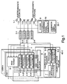
- a configuration of the apparatus of the present invention is described with reference to Fig. 1.
- the array antenna calibration apparatus of the present invention comprises a plurality of antenna elements 1-2 through 1-5 which makes up an array antenna, receivers 2-1 through 2-4 connected to said antenna elements respectively, propagation factor estimators 4-1 through 4-4 which estimate propagation factors of user signals output from said receivers 2-1 through 2-4 respectively, antenna elements 1-1 and 1-6 which send a calibration signal to said array antenna, a calibration signal supplier 30-1 which transmits an equi-amplitude/equi-phase calibration signal from said antenna elements 1-1 and 1-6, a calibration factor supplier 40 which has means for obtaining a relative phase fluctuation and a relative amplitude fluctuation between said array antenna and said antenna elements, and a beam former 3 which calibrates said user signal received by each of said antenna elements of said array antenna based on said relative phase fluctuation and said relative amplitude fluctuation.
- the calibration signal supplier 30-1 has a calibration signal generator 10 and a divider 9 for transmitting an equi-amplitude/equi-phase calibration signal, for supplying the calibration signal to the antennas 1-1 and 1-6 added to the two ends of the array antenna respectively so that the phase characteristics and the amplitude characteristics of outputs of the receivers 2-1 through 2-4 connected to the antenna elements 1-2 through 1-5 respectively may be made uniform.
- a calibration factor supplier 40-1 is comprised of a calibration signal processor 6 which processes the calibration signal received by the antenna elements 1-2 and 1-5 at the two ends of the array antenna to which the receivers 2-1 and 2-4 are connected respectively and a calibration factor calculator 5 which calculates a calibration factor using the information of a phase difference of the calibration signal sent from the calibration signal processor 6 and a transmission path estimate value sent from each of the transmission path estimators 4-1 through 4-4 of each user.
- the calibration factor supplier 40-1 obtains a relative phase fluctuation and a relative amplitude fluctuation between the antenna elements of the array antenna based on the calibration signal received by the antenna element and the user signal received by each of the antenna elements of the array antenna, thus sending the calibration factor to the beam former 3.
- the calibration signals transmitted from the antenna elements 1-1 and 1-6 are received by the receivers 2-1 and 2-4 through the antenna elements 1-2 and 1-5, respectively, owing to electromagnetic coupling between the antenna elements.
- the calibration signals received by the receivers 2-1 and 2-4 are sent to propagation factor estimators 8-1 and 8-2 of the calibration signal processor 6 respectively for estimation of their respective propagation factors.
- the resulting propagation factors are used by a phase difference calculator 7 of the calibration signal processor 6 to calculate a phase difference between the outputs of the receivers 2-1 and 2-4 and then send it to the calibration factor calculator 5.
- the user signals are received through the antenna elements 1-2 through 1-5 and the receivers 2-1 through 2-4 in this order and sent to the propagation factor estimators 4-1 through 4-4, where propagation factors of these user signals received at the antenna elements are estimated and output as a propagation factor.
- propagation estimate value is sent to the beam former 3 to be used to form a user-specific beam and also sent to the calibration factor calculator 5.
- the calibration factor calculator 5 uses the phase difference between the calibration signals and the user-specific propagation factor at each of the antenna elements, thus calculating a calibration factor for the output of each of the receivers 2-1 through 2-4. In calculation of the calibration factor, it is not necessary to use the propagation factors of all the users but they may be selected as many as an arbitrary number. Furthermore, the calibration factor obtained by the calibration factor calculator 5 is posted sent to the beam former 3 of each of the users, to be used there in order to correct the reception signal output from each of the receivers 2-1 through 2-4 for beam formation.
- the present invention features that a user signal received and a calibration signal supplied. through inter-antenna element coupling are used to make uniform the amplitude and phase characteristics of the receivers for calibration of the antenna.
- Fig. 2 shows a configuration of a base station using a linear array antenna of a CDMA communication system.
- a basic array antenna calibration apparatus of the present invention shown in Fig. 1 is applied to the CDMA communication-system base station.
- the array antenna calibration apparatus of the present embodiment mainly comprises:
- said calibration signal supplier 30-2 in the present embodiment has a calibration signal generator 10, a spreader 18, and a divider 9 for transmitting the equi-amplitude/equi-phase spread calibration signal, to supply the spread calibration signal to the antenna elements 1-1 and 1-6 added respectively to the two ends of the array antenna in order to make uniform the phase characteristics and the amplitude characteristics of outputs of said receivers 2-1 through 2-4 connected to said antenna elements 1-2 through 1-5 respectively.
- said calibration factor supplier 40-2 in the present embodiment is comprised of a calibration signal processor 6 which processes the spread calibration signal received by the antenna elements 1-2 and 1-5 disposed respectively at the two ends of the array antenna to which the receivers 2-1 and 2-4 are connected and a calibration factor calculator 5 which calculates a calibration factor using information of the phase difference of the calibration signal sent from said calibration signal processor 6 and the propagation factor sent from said propagation factor estimators 4-1 through 4-4 of each of the users.
- the calibration signal processor 6 has despreaders 20-1 and 20-2, propagation factor estimators 8-1 and 8-2, and a phase difference calculator 7, to calculate a phase difference based on the two spread calibration signals sent respectively from the receivers 2-1 and 2-2.
- the calibration factor supplier 40-2 can obtain a relative phase fluctuation and a relative amplitude fluctuation between the antenna elements of the array antenna based on the spread calibration signals received by the antenna elements and the user signal received by each of the antenna elements. As a result, the calibration factor supplier 40-2 can sent an appropriate calibration factor to the beam former 3.
- the calibration signals transmitted in an equi-amplitude/equi-phase manner from the antenna elements 1-1 and 1-6 are received by the receivers 2-1 and 2-4 as coupled. respectively with the antenna elements 1-2 and 1-5 electro-magnetically.
- the outputs of the receivers 2-1 and 2-4 fluctuate in amplitude and phase and also time-wise due to fluctuations in characteristics of the antenna elements 1-2 and 1-5, those in characteristics of receivers 2-1 and 2-4, and those of characteristics of cables interconnecting the antenna elements 1-2 and 1-5 and the receivers 2-1 and 2-4 respectively.
- the output signals x cal1 (t) and x cal4 (t) of the respective receivers 2-1 and 2-4 are as given follows: where A 1 (t) and A 4 (t) indicate amplitude fluctuations of the receivers 2-1 and 2-4 respectively and ⁇ 1 (t) and ⁇ 4 (t) indicate phase fluctuations.
- the calibration signals output respectively from the receivers 2-1 and 2-4 are despread by despreaders 20-1 and 20-2 of the calibration signal processor 6 and then sent to propagation factor estimators 8-1 and 8-2 to estimate propagation factors based thereon, thus calculating propagation factors (calibration signal propagation factor estimation step).
- the propagation factors h cal1 (t) and h cal4 (t) are given as follows:
- a phase difference calculator 7 of the calibration signal processor 6 uses these propagation factors h cal1 (t) and h cal4 (t) to calculate a phase difference ⁇ h cal (t) between the outputs of the receivers 2-1 and 2-4 and then send it to the calibration factor calculator 5 (calibration signal phase difference calculation step).
- the phase difference ⁇ h cal (t) of the propagation factors is obtained as follows: where * indicates a conjugate complex number.
- Each of the output signals from the receivers 2-1 through 2-4 is divided by the despreaders 19-1 through 19-4 into a plurality of separate components for each of the users and paths, so that for each of the users and paths the propagation factor estimators 4-1 through 4-4 estimate propagation factors, thus calculating propagation factors (user signal propagation factor estimation step).
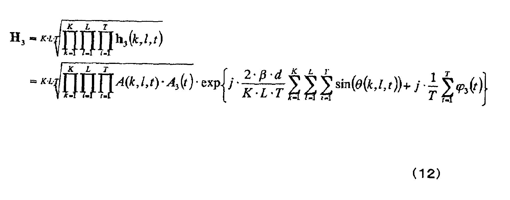
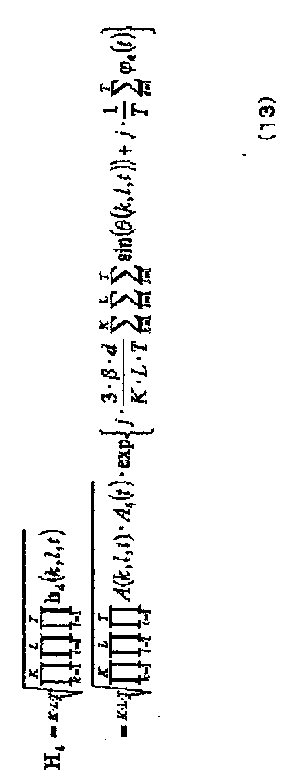
- propagation factors h 1 (k, l, t), h 2 (k, l, t), h 3 (k, l, t), and h 4 (k, 1, t) of a signal sent through path 1 from user k at a moment t are given as follows: where A 1 (t), A 2 (t), A 3 (t), and A 4 (t) indicate amplitude fluctuations of the receivers 2-1 through 2-4 respectively, and ⁇ 1 (t), ⁇ 2 (t), ⁇ 3 (t), and ⁇ 4 (t) indicate phase fluctuations of the receivers 2-1 through 2-4.
- A(k, 1, t) indicates an amplitude of user k through path 1 at a sampling moment t
- ⁇ (k, 1, t) indicates an arrival direction
- ⁇ indicates a free space propagation constant (2 ⁇ /wavelength)
- d indicates an inter-antenna element spacing.
- the estimated propagation factors h 1 (k, 1, t), h 2 (k, 1, t), h 3 (k, 1, t), and h 4 (k, 1, t) are sent to the calibration factor calculator 5.
- the calibration factor calculator 5 has a function to perform the following step to obtain a relative phase fluctuation and a relative amplitude fluctuation between the antenna elements of the array antenna in order to calculate a calibration factor for forming the beam of each of the user signals. This function is explained below along equations.
- the calibration factor calculator 5 calculates a calibration factor for each of the outputs of the receivers 2-1 through 2-4 using a phase difference ⁇ h cal (t) of the calibration signal and propagation factors h 1 (k, l, t), h 2 (k, l, t), h 3 (k, l, t), and h 4 (k, l, t) of the respective antenna elements for each user through each path.
- a phase difference ⁇ h cal (t) of the calibration signal and propagation factors h 1 (k, l, t), h 2 (k, l, t), h 3 (k, l, t), and h 4 (k, l, t) of the respective antenna elements for each user through each path.
- the calibration factor calculator 5 calculates geometric average values H 1 , H 2 , H 3 , and H 4 of the propagation factors of the samples of the users through the paths for the respective antenna elements.
- the calibration factor calculator 5 calculates a geometric average value ⁇ H cal of phase differences between the calibration signals (phase difference geometric average value calculation step)as follows:
- the calibration factor calculator 5 uses values of Equations (10), (13), and (14) to obtain a phase difference ⁇ W between the antenna elements caused by a difference in length of the arrival paths as follows (arrival path phase difference calculation step):
- the calibration factor calculator 5 uses a value of Equation (15) to thereby obtain time- averages ⁇ W ⁇ 2 and ⁇ W ⁇ 3 of the relative phase fluctuations (with respect to the antenna element 1-2) in receiver output of the antenna elements 1-3 and 1-4 as follows (first relative phase fluctuation calculation step):
- the calibration factor calculator 5 uses the calibration signal to thereby obtain a time- average ⁇ W ⁇ 4 of the relative phase fluctuations in receiver output of the antenna element 1-5 as follows (second relative phase fluctuation calculation step):
- the calibration factor calculator 5 uses geometric averages H1 through H4 to thereby obtain time-averages ⁇ A 2 , ⁇ A 3 , and ⁇ A 4 of the relative amplitude fluctuations in receiver output (with respect to the antenna element 1-2) as follows (relative amplitude fluctuation calculation step):
- Equations (16)-(18) and (19)-(21) are transformed into the following equations (26)-(28) and (29)-(31) respectively: ⁇ W ⁇ 2 ⁇ exp( ⁇ 1 -( t )- ⁇ 2 ( t )) ⁇ W ⁇ 3 ⁇ exp( ⁇ 1 ( t )- ⁇ 3 ( t )) ⁇ W ⁇ 4 ⁇ exp( ⁇ 1 ( t )- ⁇ 4 ( t )) ⁇ A 2 ⁇ A 1 ( t ) A 2 ( t ) ⁇ A 3 ⁇ A 1 ( t ) A 3 ( t ) ⁇ A 4 ⁇ A 1 ( t ) A 4 ( t )
- Equations (26)-(28) and (29)-(31) indicate the relative phase characteristics and the relative amplitude characteristics of the respective receivers 2-1 through 2-4 with respect to an output of the receiver 2-1, showing that the characteristics fluctuations in output of the receivers can be made uniform by using Equations (22)-(25) as a calibration factor.
- a calibration factor obtained by the calibration factor calculator 5 can be sent to the beam former 3 of each of the users through each of the paths, so that the calibration factor calibration factor can be applied to an output signal of each of the receivers 2-1 through 2-5 at the beam former through each of the paths for each of the users, thus removing the fluctuations in amplitude and phase of each of the receivers 2-1 through 2-4.
- accurate beam forming is possible.
- a calibration signal supplier 30-3 comprises the calibration signal generator 10 and a coupler which supplies a calibration signal to an arbitrary antenna element 1-3 of the antenna elements 1-2 through 1-4 connected with the receivers 2-1 through 2-4 respectively except both ends.
- the array antenna here is a typical linear array antenna, in which the antenna elements 1-1 and 1-6 disposed at the two ends are non-reflection terminators 17-1 and 17-2 respectively.
- the calibration signal is transmitted by the arbitrary antenna element 1-3 of the antenna elements 1-2 through 1-4 connected with the receivers 2-1 through 2-4 respectively except both ends, to cause the antenna elements 1-2 and 1-4 respectively adjacent the antenna element 1-3 to measure electro-magnetically coupled calibration signals.
- measured calibration signals can be used to perform calibration processing almost the same way as the first embodiment.
- a calibration signal supplier 30-4 comprises the calibration signal generator 10, the divider 9, and a plurality of couplers 221-1 through 221-3 in such a configuration that the calibration signal is transmitted to an arbitrary number of antenna elements selected from antenna elements 201-2 through 201-9 connected to receivers 202-1 through 202-8 respectively.
- the same calibration signal is transmitted from an arbitrary number of the antenna elements selected from the antenna elements 201-1 through 201-9 connected to the receivers 202-1 through 202-8 respectively, so that the calibration signals detected by them can be used to perform calibration almost the same way as the first embodiment.
- phase difference calculator 7 of the calibration signal processor 6 uses as a phase difference a gradient which is given when the phases of the four propagation factors are approximated linearly. It is thus possible to mitigate the influence by the fluctuations in characteristics of the divider or the coupler on the calibration accuracy.
- the present invention is applicable also to a base station of a TDMA or FDMA communication system.
- the calibration signal is measured by allocating a time slot for the calibration signal or using an empty time slot to input the calibration signal therein.
- the propagation factors are estimated for a plurality of time slots and subjected to geometric averaging.
- the calibration signal is measured by allocating a frequency channel for the calibration signal or using an empty frequency channel to input the calibration signal therein.
- the propagation factors are estimated for a plurality of frequency channels and subjected to geometric averaging.
- phase difference and average propagation factor of the calibration signals are used to calculate a calibration factor.
- the fluctuations in relative amplitude and relative phase of a path ranging from the incident surfaces of the antenna elements to the outputs of the receivers can be removed without providing an external calibration station, thus giving an effect of accurate beam forming.
Landscapes
- Variable-Direction Aerials And Aerial Arrays (AREA)
- Radio Transmission System (AREA)
Abstract
Description
The following will describe embodiments of the present invention with reference to drawings.













Claims (6)
- A calibration apparatus used in an array antenna having a plurality of antenna elements, comprising:a plurality of first antenna elements in said antenna elements for calibration;a calibration signal supplier for supplying a calibration signal to a second antenna element near at least two said first antenna elements of said array antenna, or a coupler connected to said first antenna element;a calibration factor supplier for obtaining a relative phase fluctuation and a relative amplitude fluctuation between said antenna elements of said array antenna based on the calibration signal received by said at least two first antenna elements and user signals received respectively by said antenna elements of said array antenna; anda beam former for calibrating said user signals received respectively by said antenna elements of said array antenna using said relative phase fluctuation and said relative amplitude fluctuation.
- The calibration apparatus as claimed in claim 1, wherein said calibration factor supplier for obtaining the relative phase fluctuation comprises
means for obtaining a propagation factor relating to said calibration signal for each of said first antenna elements based on said calibration signal received by each of said first antenna elements;
means for obtaining a first phase difference of said propagation factor relating to said calibration signal between said first antenna elements based on said propagation factor;
means for obtaining an average of said phase differences of said propagation factors relating to said calibration signals between said first antenna elements based on said phase differences of said propagation factors;
means for obtaining an average of the propagation factors relating to said user signals for each of said antenna elements of said array antenna based on said user signals;
means for obtaining a phase difference between said antenna elements caused by a difference in length of arrival paths based on said average of said phase differences and said average of said propagation factors;
means for obtaining a first time-average of the relative phase fluctuations of each of said antenna elements with respect to the one of said first antenna elements as a reference, based on said average of said propagation factors relating to said user signals for each of said antenna elements of said array antenna, said average of said propagation factors relating to said user signals for each of said first antenna elements, and said phase difference between said antenna elements caused by the difference in length of said arrival paths; and
means for obtaining a second time-average of the relative phase fluctuations of said first antenna which are not used as a reference, based on the phase difference of said propagation factors relating to said calibration signal between said first antenna elements. - The calibration apparatus as claimed in claim 1, wherein said calibration factor supplier for obtaining the relative amplitude fluctuation comprises
means for obtaining the propagation factor relating to said calibration signal for each of said first antenna elements based on said calibration signal received by each of said first antenna elements;
means for obtaining the phase difference of said propagation factor relating to said calibration signal between said first antenna elements based on said propagation factor relating to said calibration signal;
means for obtaining the average of said phase differences of said propagation factors relating to said calibration signals between said first antenna elements based on said phase differences of said propagation factors;
means for obtaining the average of said propagation factors relating to said user signals for each of said antenna elements of said array antenna;
means for obtaining the phase difference between said antenna elements caused by the difference in length of the arrival paths based on said average of said phase differences of said propagation factors and said average of said propagation factors; and
means for obtaining a time-average of the relative amplitude fluctuations for each of said antenna elements of said array antenna with respect to one of said antenna elements of said array antenna based on said average of the propagation factors. - An array antenna calibrating method comprising the steps of:supplying a calibration signal to a second antenna element near at least two said first antenna elements of said array antenna, or a coupler connected to said first antenna element;obtaining a relative phase fluctuation and a relative amplitude fluctuation between said antenna elements of said array antenna based on the calibration signal received by said at least two first antenna elements and user signals received respectively by said antenna elements of said array antenna; andcalibrating said user signals received respectively by said antenna elements of said array antenna using said relative phase fluctuation and said relative amplitude fluctuation.
- The array antenna calibrating method as claimed in claim 4, wherein said step for obtaining the relative phase fluctuation comprises
a calibration signal propagation factor estimating step for obtaining a propagation factor relating to said calibration signal for each of said first antenna elements based on said calibration signal received by each of said first antenna elements;
a calibration signal phase difference calculating step for obtaining a first phase difference of said propagation factor relating to said calibration signal between said first antenna elements based on said propagation factor;
a phase difference geometric average calculating step for obtaining an average of said phase differences of said propagation factors relating to said calibration signals between said first antenna elements based on said phase differences of said propagation factors;
a user signal propagation factor estimating step for obtaining an average of the propagation factors relating to said user signals for each of said antenna elements of said array antenna based on said user signals;
an arrival path phase difference calculating step for obtaining a phase difference between said antenna elements caused by a difference in length of arrival paths based on said average of said phase differences and said average of said propagation factors;
a first relative phase fluctuation calculating step for obtaining a first time-average of the relative phase fluctuations of each of said antenna elements with respect to the one of said first antenna elements as a reference, based on said average of said propagation factors relating to said user signals for each of said antenna elements of said array antenna, said average of said propagation factors relating to said user signals for each of said first antenna elements, and said phase difference between said antenna elements caused by the difference in length of said arrival paths; and
a second relative phase fluctuation calculating step for obtaining a second time-average of the relative phase fluctuations of said first antenna which are not used as a reference, based on the phase difference of said propagation factors relating to said calibration signal between said first antenna elements. - The array antenna calibrating method as claimed in claim 4, wherein said step for obtaining the relative amplitude fluctuation comprises
a calibration signal propagation factor estimating step for obtaining the propagation factor relating to said calibration signal for each of said first antenna elements based on said calibration signal received by each of said first antenna elements;
a calibration signal phase difference calculating step for obtaining the phase difference of said propagation factor relating to said calibration signal between said first antenna elements based on said propagation factor relating to said calibration signal;
a phase difference geometric average calculating step for obtaining the average of said phase differences of said propagation factors relating to said calibration signals between said first antenna elements based on said phase differences of said propagation factors;
a user signal propagation factor estimating step for obtaining the average of said propagation factors relating to said'user signals for each of said antenna elements of said array antenna;
an arrival path phase difference calculating step for obtaining the phase difference between said antenna elements caused by the difference in length of the arrival paths based on said average of said phase differences of said propagation factors and said average of said propagation factors; and
a relative amplitude fluctuation calculating step for obtaining a time-average of the relative amplitude fluctuations for each of said antenna elements of said array antenna with respect to one of said antenna elements of said array antenna based on said average of the propagation factors.
Applications Claiming Priority (2)
| Application Number | Priority Date | Filing Date | Title |
|---|---|---|---|
| JP2001281662A JP3651430B2 (en) | 2001-09-17 | 2001-09-17 | Array antenna calibration apparatus and calibration method |
| JP2001281662 | 2001-09-17 |
Publications (2)
| Publication Number | Publication Date |
|---|---|
| EP1294047A2 true EP1294047A2 (en) | 2003-03-19 |
| EP1294047A3 EP1294047A3 (en) | 2006-01-04 |
Family
ID=19105445
Family Applications (1)
| Application Number | Title | Priority Date | Filing Date |
|---|---|---|---|
| EP02020568A Withdrawn EP1294047A3 (en) | 2001-09-17 | 2002-09-17 | Apparatus and method for calibrating array antenna |
Country Status (5)
| Country | Link |
|---|---|
| US (1) | US6762717B2 (en) |
| EP (1) | EP1294047A3 (en) |
| JP (1) | JP3651430B2 (en) |
| KR (1) | KR100482018B1 (en) |
| CN (1) | CN1237828C (en) |
Cited By (8)
| Publication number | Priority date | Publication date | Assignee | Title |
|---|---|---|---|---|
| EP1708385A3 (en) * | 2005-03-30 | 2006-11-22 | Fujitsu Limited | Apparatus for calibrating the phases of an antenna array |
| EP1724875A1 (en) | 2005-05-19 | 2006-11-22 | Fujitsu Limited | Array antenna calibration apparatus and method |
| EP1732163A1 (en) * | 2005-06-10 | 2006-12-13 | Fujitsu Limited | Calibration apparatus and method for array antenna |
| WO2009083961A1 (en) * | 2007-12-31 | 2009-07-09 | Elta Systems Ltd | Phased array antenna having integral calibration network and method for measuring calibration ratio thereof |
| CN101500248B (en) * | 2008-01-31 | 2011-02-02 | 大唐移动通信设备有限公司 | Antenna calibration method and apparatus |
| US8212716B2 (en) | 2007-12-31 | 2012-07-03 | Elta Systems Ltd. | System and method for calibration of phased array antenna having integral calibration network in presence of an interfering body |
| CN111289950A (en) * | 2020-03-06 | 2020-06-16 | 南京长峰航天电子科技有限公司 | Signal channel calibration method and device based on correlation and least square |
| CN111289808A (en) * | 2020-02-25 | 2020-06-16 | 广州兴森快捷电路科技有限公司 | Method for dynamically monitoring amplitude and phase deviation |
Families Citing this family (55)
| Publication number | Priority date | Publication date | Assignee | Title |
|---|---|---|---|---|
| JP4226442B2 (en) * | 2002-11-14 | 2009-02-18 | パナソニック株式会社 | Wireless communication device |
| DE10301125B3 (en) * | 2003-01-14 | 2004-06-24 | Eads Deutschland Gmbh | Transmission and reception path calibration method for antenna system, has calibration signals provided by amplification of base signal within defined limits of reference signal |
| KR100981554B1 (en) * | 2003-11-13 | 2010-09-10 | 한국과학기술원 | In a mobile communication system having multiple transmit / receive antennas, a method of transmitting signals by grouping transmit antennas |
| CN100399730C (en) * | 2003-12-03 | 2008-07-02 | 电子科技大学 | A Blind Estimation Method of Array Antenna Channel Error |
| JP4209355B2 (en) * | 2004-03-30 | 2009-01-14 | 富士通株式会社 | Phase calibration method and phase calibration apparatus |
| JP2006005525A (en) * | 2004-06-16 | 2006-01-05 | Nec Corp | Transmission apparatus |
| KR100706229B1 (en) | 2004-12-21 | 2007-04-11 | 삼성전자주식회사 | Multiple transceiver system and method for compensating carrier frequency difference between embedded transceivers |
| KR100677557B1 (en) * | 2005-01-19 | 2007-02-02 | 삼성전자주식회사 | Calibration device capable of calibrating and its calibration method |
| JP4562542B2 (en) * | 2005-02-15 | 2010-10-13 | 三洋電機株式会社 | CALIBRATION METHOD AND BASE STATION DEVICE, TERMINAL DEVICE, AND RADIO DEVICE USING THE SAME |
| US20060240784A1 (en) * | 2005-04-22 | 2006-10-26 | Qualcomm Incorporated | Antenna array calibration for wireless communication systems |
| US8498669B2 (en) | 2005-06-16 | 2013-07-30 | Qualcomm Incorporated | Antenna array calibration for wireless communication systems |
| US7633905B1 (en) | 2005-09-02 | 2009-12-15 | Magnolia Broadband Inc. | Calibrating a transmit diversity communication device |
| US9118111B2 (en) | 2005-11-02 | 2015-08-25 | Qualcomm Incorporated | Antenna array calibration for wireless communication systems |
| CA2628478C (en) * | 2005-11-02 | 2016-05-17 | Qualcomm Incorporated | Antenna array calibration for wireless communication systems |
| US8280430B2 (en) | 2005-11-02 | 2012-10-02 | Qualcomm Incorporated | Antenna array calibration for multi-input multi-output wireless communication systems |
| TWI356600B (en) * | 2005-11-02 | 2012-01-11 | Qualcomm Inc | Antenna array calibration for wireless communicati |
| US7218273B1 (en) * | 2006-05-24 | 2007-05-15 | L3 Communications Corp. | Method and device for boresighting an antenna on a moving platform using a moving target |
| CN101483274B (en) * | 2009-02-24 | 2012-06-13 | 中国航天科技集团公司第五研究院第五○四研究所 | External calibration method for phase variable power detecting array antenna |
| KR101172240B1 (en) * | 2010-05-18 | 2012-08-07 | 주식회사 만도 | Sensor and alignment adjusting method |
| CN103229354A (en) * | 2010-12-01 | 2013-07-31 | 瑞典爱立信有限公司 | Method, antenna array, computer program and computer program product for obtaining at least one calibration parameter |
| CN102571170B (en) * | 2011-12-23 | 2014-11-19 | 北京遥测技术研究所 | A method for real-time calibration of uplink antenna array link changes |
| KR101405260B1 (en) * | 2013-07-05 | 2014-06-27 | 국방과학연구소 | Self calibration Method for Global Positioning System signal beamforming and Apparatus thereof |
| JP6271032B2 (en) * | 2014-10-30 | 2018-01-31 | 三菱電機株式会社 | Antenna specification estimating device and radar device |
| KR101638481B1 (en) * | 2015-01-09 | 2016-07-11 | 국방과학연구소 | Method and Apparatus for correcting interferometer of array antenna with tilt angle |
| JP6561867B2 (en) * | 2016-02-15 | 2019-08-21 | 株式会社デンソー | Multiple transmitting antenna phase calibration device |
| US9689967B1 (en) * | 2016-04-07 | 2017-06-27 | Uhnder, Inc. | Adaptive transmission and interference cancellation for MIMO radar |
| US9846228B2 (en) | 2016-04-07 | 2017-12-19 | Uhnder, Inc. | Software defined automotive radar systems |
| US10261179B2 (en) | 2016-04-07 | 2019-04-16 | Uhnder, Inc. | Software defined automotive radar |
| US9772397B1 (en) | 2016-04-25 | 2017-09-26 | Uhnder, Inc. | PMCW-PMCW interference mitigation |
| US10573959B2 (en) | 2016-04-25 | 2020-02-25 | Uhnder, Inc. | Vehicle radar system using shaped antenna patterns |
| US9791551B1 (en) * | 2016-04-25 | 2017-10-17 | Uhnder, Inc. | Vehicular radar system with self-interference cancellation |
| US9575160B1 (en) | 2016-04-25 | 2017-02-21 | Uhnder, Inc. | Vehicular radar sensing system utilizing high rate true random number generator |
| WO2017187306A1 (en) | 2016-04-25 | 2017-11-02 | Uhnder, Inc. | Adaptive filtering for fmcw interference mitigation in pmcw radar systems |
| WO2017187299A2 (en) | 2016-04-25 | 2017-11-02 | Uhnder, Inc. | Successive signal interference mitigation |
| US9599702B1 (en) | 2016-04-25 | 2017-03-21 | Uhnder, Inc. | On-demand multi-scan micro doppler for vehicle |
| US9954955B2 (en) | 2016-04-25 | 2018-04-24 | Uhnder, Inc. | Vehicle radar system with a shared radar and communication system |
| US9945935B2 (en) | 2016-04-25 | 2018-04-17 | Uhnder, Inc. | Digital frequency modulated continuous wave radar using handcrafted constant envelope modulation |
| US10263330B2 (en) * | 2016-05-26 | 2019-04-16 | Nokia Solutions And Networks Oy | Antenna elements and apparatus suitable for AAS calibration by selective couplerline and TRX RF subgroups |
| US9753121B1 (en) | 2016-06-20 | 2017-09-05 | Uhnder, Inc. | Power control for improved near-far performance of radar systems |
| DE102016212136A1 (en) * | 2016-07-04 | 2018-01-04 | Laird Bochum GmbH | Method and device for determining a distance and vehicle |
| WO2018051288A1 (en) | 2016-09-16 | 2018-03-22 | Uhnder, Inc. | Virtual radar configuration for 2d array |
| EP3306838B8 (en) * | 2016-10-06 | 2019-06-05 | Rohde & Schwarz GmbH & Co. KG | System and method for testing antenna arrays |
| WO2018146530A1 (en) | 2017-02-10 | 2018-08-16 | Uhnder, Inc. | Reduced complexity fft-based correlation for automotive radar |
| US11454697B2 (en) | 2017-02-10 | 2022-09-27 | Uhnder, Inc. | Increasing performance of a receive pipeline of a radar with memory optimization |
| US9971020B1 (en) | 2017-02-10 | 2018-05-15 | Uhnder, Inc. | Radar data buffering |
| CN111133691B (en) * | 2017-09-28 | 2021-07-09 | 华为技术有限公司 | A method, device and system for calibrating an array antenna |
| US11105890B2 (en) | 2017-12-14 | 2021-08-31 | Uhnder, Inc. | Frequency modulated signal cancellation in variable power mode for radar applications |
| US12386029B2 (en) | 2018-01-29 | 2025-08-12 | Robert Bosch Gmbh | Millimeter wave automotive radar systems |
| CN110620605B (en) * | 2018-06-20 | 2021-04-16 | 大唐移动通信设备有限公司 | Detection method and device for array antenna receiving calibration |
| JP7091197B2 (en) | 2018-09-10 | 2022-06-27 | 株式会社東芝 | Wireless communication equipment and wireless communication systems |
| US11474225B2 (en) | 2018-11-09 | 2022-10-18 | Uhnder, Inc. | Pulse digital mimo radar system |
| US11681017B2 (en) | 2019-03-12 | 2023-06-20 | Uhnder, Inc. | Method and apparatus for mitigation of low frequency noise in radar systems |
| US11953615B2 (en) | 2020-01-13 | 2024-04-09 | Uhnder Inc. | Method and system for antenna array calibration for cross-coupling and gain/phase variations in radar systems |
| WO2023100108A1 (en) | 2021-12-02 | 2023-06-08 | Uhnder, Inc. | Radar system with enhanced processing for increased contrast ratio, improved angular separability and elimination of ghost targets |
| KR102913347B1 (en) * | 2023-08-22 | 2026-01-15 | 국방과학연구소 | Error correction apparatus for monopulse radar system with high angle accuracy |
Family Cites Families (12)
| Publication number | Priority date | Publication date | Assignee | Title |
|---|---|---|---|---|
| US5027127A (en) * | 1985-10-10 | 1991-06-25 | United Technologies Corporation | Phase alignment of electronically scanned antenna arrays |
| US5412414A (en) * | 1988-04-08 | 1995-05-02 | Martin Marietta Corporation | Self monitoring/calibrating phased array radar and an interchangeable, adjustable transmit/receive sub-assembly |
| BR9507801A (en) * | 1994-06-03 | 1998-05-26 | Ericsson Telefon Ab L M | Process and system for calibrating the transmission and reception of an antenna array for use in a mobile radio communications system |
| US6157343A (en) * | 1996-09-09 | 2000-12-05 | Telefonaktiebolaget Lm Ericsson | Antenna array calibration |
| JPH10336149A (en) | 1997-05-28 | 1998-12-18 | Matsushita Electric Ind Co Ltd | Array antenna wireless CDMA communication device |
| DE69930384T2 (en) * | 1998-07-13 | 2006-12-07 | Ntt Mobile Communications Network Inc. | ADAPTIVE GROUP ANTENNA |
| ID27970A (en) * | 1998-08-05 | 2001-05-03 | Sanyo Electric Co | RADAS RADIO AND CALIBRATION METHODS FOR THAT |
| GB2342505B (en) | 1998-10-06 | 2003-06-04 | Telecom Modus Ltd | Antenna array calibration |
| JP2000295152A (en) | 1999-04-01 | 2000-10-20 | Matsushita Electric Ind Co Ltd | Array antenna wireless communication device |
| JP4303373B2 (en) * | 1999-09-14 | 2009-07-29 | 株式会社日立コミュニケーションテクノロジー | Wireless base station equipment |
| JP3557969B2 (en) * | 1999-11-24 | 2004-08-25 | 日本電気株式会社 | Wireless receiver and calibration method |
| KR100444822B1 (en) * | 2001-08-07 | 2004-08-18 | 한국전자통신연구원 | Apparatus for Calibration in Adaptive Array Antenna and Method Thereof |
-
2001
- 2001-09-17 JP JP2001281662A patent/JP3651430B2/en not_active Expired - Fee Related
-
2002
- 2002-09-12 US US10/241,557 patent/US6762717B2/en not_active Expired - Lifetime
- 2002-09-17 CN CNB021426945A patent/CN1237828C/en not_active Expired - Fee Related
- 2002-09-17 EP EP02020568A patent/EP1294047A3/en not_active Withdrawn
- 2002-09-17 KR KR10-2002-0056454A patent/KR100482018B1/en not_active Expired - Fee Related
Cited By (16)
| Publication number | Priority date | Publication date | Assignee | Title |
|---|---|---|---|---|
| EP1708385A3 (en) * | 2005-03-30 | 2006-11-22 | Fujitsu Limited | Apparatus for calibrating the phases of an antenna array |
| EP1830486A1 (en) * | 2005-03-30 | 2007-09-05 | Fujitsu Ltd. | Calibration apparatus |
| US7340248B2 (en) | 2005-03-30 | 2008-03-04 | Fujitsu Limited | Calibration apparatus |
| EP1940047A1 (en) * | 2005-03-30 | 2008-07-02 | Fujitsu Limited | Apparatus for calibrating the phases of an antenna array |
| EP1724875A1 (en) | 2005-05-19 | 2006-11-22 | Fujitsu Limited | Array antenna calibration apparatus and method |
| US7545321B2 (en) | 2005-05-19 | 2009-06-09 | Fujitsu Limited | Array antenna calibration apparatus and method |
| EP1732163A1 (en) * | 2005-06-10 | 2006-12-13 | Fujitsu Limited | Calibration apparatus and method for array antenna |
| US7248216B2 (en) | 2005-06-10 | 2007-07-24 | Fujitsu Limited | Calibration apparatus and method for array antenna |
| WO2009083961A1 (en) * | 2007-12-31 | 2009-07-09 | Elta Systems Ltd | Phased array antenna having integral calibration network and method for measuring calibration ratio thereof |
| US8013783B2 (en) | 2007-12-31 | 2011-09-06 | Elta Systems Ltd. | Phased array antenna having integral calibration network and method for measuring calibration ratio thereof |
| US8212716B2 (en) | 2007-12-31 | 2012-07-03 | Elta Systems Ltd. | System and method for calibration of phased array antenna having integral calibration network in presence of an interfering body |
| AU2008344938B2 (en) * | 2007-12-31 | 2012-09-20 | Elta Systems Ltd | Phased array antenna having integral calibration network and method for measuring calibration ratio thereof |
| CN101500248B (en) * | 2008-01-31 | 2011-02-02 | 大唐移动通信设备有限公司 | Antenna calibration method and apparatus |
| CN111289808A (en) * | 2020-02-25 | 2020-06-16 | 广州兴森快捷电路科技有限公司 | Method for dynamically monitoring amplitude and phase deviation |
| CN111289808B (en) * | 2020-02-25 | 2022-09-13 | 广州兴森快捷电路科技有限公司 | Method for dynamically monitoring amplitude and phase deviation |
| CN111289950A (en) * | 2020-03-06 | 2020-06-16 | 南京长峰航天电子科技有限公司 | Signal channel calibration method and device based on correlation and least square |
Also Published As
| Publication number | Publication date |
|---|---|
| US6762717B2 (en) | 2004-07-13 |
| JP2003092508A (en) | 2003-03-28 |
| KR100482018B1 (en) | 2005-04-13 |
| CN1237828C (en) | 2006-01-18 |
| JP3651430B2 (en) | 2005-05-25 |
| EP1294047A3 (en) | 2006-01-04 |
| CN1406088A (en) | 2003-03-26 |
| KR20030024625A (en) | 2003-03-26 |
| US20030058166A1 (en) | 2003-03-27 |
Similar Documents
| Publication | Publication Date | Title |
|---|---|---|
| EP1294047A2 (en) | Apparatus and method for calibrating array antenna | |
| US7057555B2 (en) | Wireless LAN with distributed access points for space management | |
| US6693588B1 (en) | Method for calibrating an electronically phase-controlled group antenna in radio communications systems | |
| EP3347993B1 (en) | Calibrating a serial interconnection | |
| EP1438768B1 (en) | Frequency dependent calibration of a wideband radio system using narrowband channels | |
| EP1585231B1 (en) | A method for calibrating smart antenna array systems in real time | |
| EP1784658B1 (en) | Antenna array calibration | |
| EP1433271B1 (en) | Calibration of a radio communications system | |
| EP1670094B1 (en) | Smart antenna communication system for signal calibration | |
| US12136772B2 (en) | Self-calibrating phased-array transceiver | |
| EP1994425B1 (en) | System and method for performing time difference of arrival location without requiring a common time base or clock calibration | |
| US10230163B2 (en) | Monopulse autotracking system for high gain antenna pointing | |
| US11422220B2 (en) | Method and apparatus for determining the angle of departure | |
| US20200287620A1 (en) | System for calibrating from the ground a payload of a satellite | |
| US10541462B2 (en) | Method for elimination of antenna angular orientation error in point-to-point communication system | |
| US10945223B2 (en) | Method for detecting synchronization deviation between communication stations | |
| EP0152482B1 (en) | Direction finding interferometer internal calibration system | |
| WO2020189114A1 (en) | Radar device | |
| JP2965503B2 (en) | Array antenna control device | |
| EP3520169B1 (en) | Distributing coherent signals to large electrical distances over serial interconnections | |
| US20260086192A1 (en) | Radar device with self-interference based compensation | |
| US20240248168A1 (en) | Method and arrangement for evaluating a distance between at least two antenna units | |
| JP7233312B2 (en) | Radiation power estimation method | |
| EP4621437A1 (en) | Antenna apparatus, radar, terminal device, and vehicle end | |
| US20250233611A1 (en) | Rf device with a communication mismatch self-calibration |
Legal Events
| Date | Code | Title | Description |
|---|---|---|---|
| PUAI | Public reference made under article 153(3) epc to a published international application that has entered the european phase |
Free format text: ORIGINAL CODE: 0009012 |
|
| AK | Designated contracting states |
Kind code of ref document: A2 Designated state(s): AT BE BG CH CY CZ DE DK EE ES FI FR GB GR IE IT LI LU MC NL PT SE SK TR Designated state(s): AT BE BG CH CY CZ DE DK EE ES FI FR GB GR IE IT LI LU MC NL PT SE SK TR |
|
| AX | Request for extension of the european patent |
Extension state: AL LT LV MK RO SI |
|
| PUAL | Search report despatched |
Free format text: ORIGINAL CODE: 0009013 |
|
| AK | Designated contracting states |
Kind code of ref document: A3 Designated state(s): AT BE BG CH CY CZ DE DK EE ES FI FR GB GR IE IT LI LU MC NL PT SE SK TR |
|
| AX | Request for extension of the european patent |
Extension state: AL LT LV MK RO SI |
|
| 17P | Request for examination filed |
Effective date: 20051125 |
|
| AKX | Designation fees paid |
Designated state(s): DE FR GB |
|
| 17Q | First examination report despatched |
Effective date: 20100922 |
|
| STAA | Information on the status of an ep patent application or granted ep patent |
Free format text: STATUS: THE APPLICATION IS DEEMED TO BE WITHDRAWN |
|
| 18D | Application deemed to be withdrawn |
Effective date: 20150401 |