EP1294046A2 - Internal broadcast reception system for mobile phones - Google Patents
Internal broadcast reception system for mobile phones Download PDFInfo
- Publication number
- EP1294046A2 EP1294046A2 EP02018345A EP02018345A EP1294046A2 EP 1294046 A2 EP1294046 A2 EP 1294046A2 EP 02018345 A EP02018345 A EP 02018345A EP 02018345 A EP02018345 A EP 02018345A EP 1294046 A2 EP1294046 A2 EP 1294046A2
- Authority
- EP
- European Patent Office
- Prior art keywords
- signals
- broadcast
- reception system
- mobile phone
- broadcast reception
- Prior art date
- Legal status (The legal status is an assumption and is not a legal conclusion. Google has not performed a legal analysis and makes no representation as to the accuracy of the status listed.)
- Ceased
Links
- 239000000758 substrate Substances 0.000 claims abstract description 66
- 230000005236 sound signal Effects 0.000 claims abstract description 7
- 230000003321 amplification Effects 0.000 claims description 8
- 238000003199 nucleic acid amplification method Methods 0.000 claims description 8
- 239000000463 material Substances 0.000 claims description 6
- 238000007781 pre-processing Methods 0.000 abstract description 27
- 238000001914 filtration Methods 0.000 abstract description 2
- 238000010586 diagram Methods 0.000 description 8
- 239000003990 capacitor Substances 0.000 description 5
- 238000000034 method Methods 0.000 description 2
- 229920001940 conductive polymer Polymers 0.000 description 1
- 238000004519 manufacturing process Methods 0.000 description 1
Images





Classifications
-
- H—ELECTRICITY
- H01—ELECTRIC ELEMENTS
- H01Q—ANTENNAS, i.e. RADIO AERIALS
- H01Q1/00—Details of, or arrangements associated with, antennas
- H01Q1/12—Supports; Mounting means
- H01Q1/22—Supports; Mounting means by structural association with other equipment or articles
- H01Q1/24—Supports; Mounting means by structural association with other equipment or articles with receiving set
- H01Q1/241—Supports; Mounting means by structural association with other equipment or articles with receiving set used in mobile communications, e.g. GSM
- H01Q1/242—Supports; Mounting means by structural association with other equipment or articles with receiving set used in mobile communications, e.g. GSM specially adapted for hand-held use
- H01Q1/243—Supports; Mounting means by structural association with other equipment or articles with receiving set used in mobile communications, e.g. GSM specially adapted for hand-held use with built-in antennas
-
- H—ELECTRICITY
- H01—ELECTRIC ELEMENTS
- H01Q—ANTENNAS, i.e. RADIO AERIALS
- H01Q1/00—Details of, or arrangements associated with, antennas
- H01Q1/08—Means for collapsing antennas or parts thereof
- H01Q1/084—Pivotable antennas
-
- H—ELECTRICITY
- H01—ELECTRIC ELEMENTS
- H01Q—ANTENNAS, i.e. RADIO AERIALS
- H01Q1/00—Details of, or arrangements associated with, antennas
- H01Q1/36—Structural form of radiating elements, e.g. cone, spiral, umbrella; Particular materials used therewith
- H01Q1/362—Structural form of radiating elements, e.g. cone, spiral, umbrella; Particular materials used therewith for broadside radiating helical antennas
-
- H—ELECTRICITY
- H01—ELECTRIC ELEMENTS
- H01Q—ANTENNAS, i.e. RADIO AERIALS
- H01Q1/00—Details of, or arrangements associated with, antennas
- H01Q1/36—Structural form of radiating elements, e.g. cone, spiral, umbrella; Particular materials used therewith
- H01Q1/38—Structural form of radiating elements, e.g. cone, spiral, umbrella; Particular materials used therewith formed by a conductive layer on an insulating support
-
- H—ELECTRICITY
- H01—ELECTRIC ELEMENTS
- H01Q—ANTENNAS, i.e. RADIO AERIALS
- H01Q23/00—Antennas with active circuits or circuit elements integrated within them or attached to them
Definitions
- the present invention relates generally to an internal antenna for use in a hand-held device such as a mobile phone and, more particularly, to an internal reception system for receiving FM/digital broadcast signals.
- FM broadcast signals are commonly transmitted with carrier waves in the frequency range of 88-108 MHz.
- FM broadcasting is also referred to as very high frequency (VHF) radio broadcasting.
- VHF very high frequency
- a quarter-wave antenna having a length in the order of 85 cm is required.
- hand-held devices usually use external antennas, such as telescope-type antennas and head-set wires for FM broadcast reception.
- the major disadvantages of such external antennas are that they are visibly obtrusive and they increase the weight and the size of the hand-held device.
- the entire reception system can be disposed within the housing of the mobile phone without external parts connecting to the reception system.
- the reception system is lightweight, cost effective, easy to produce, and can be easily interfaced with other mechanical and electronic components in the mobile phone.
- the above objective can be achieved by integrating an FM/digital antenna with necessary signal processing electronics on a common substrate, which has a small size to be disposed entirely within the housing of the mobile phone.
- the first aspect of the present invention is an integrated reception system for use in a hand-held telecommunication device for receiving frequency-modulation broadcast signals or digital broadcast signals, wherein the hand-held telecommunication device has a device body.
- the integrated reception system comprises:
- the hand-held telecommunication device includes a chassis for disposing telecommunication components.
- the substrate can be a part of the chassis or a separate part but mechanically and electrically connected to the chassis.
- the electrically non-conductive substrate can be rigid or flexible.
- the electrically conductive element may have a meandering pattern in order to reduce the size of the electrically non-conductive substrate.
- the electrically conductive element may be wound around the electrically non-conductive substrate so as to reduce the physical size of the electrically conductive element and, therefore, the size of the electrically non-conductive susbstrate.
- the signal processing module may include a band-tune circuit for selecting a frequency band.
- the signal processing module may include an active amplifier to amplify the received signals.
- a mobile phone capable of receiving broadcast signals.
- the mobile phone comprises:
- the broadcast signals are frequency-modulated broadcast signals
- the signal processing module may include a tuning circuit for selecting a channel and a demodulating device for converting the broadcast signals to audio signals.
- the broadcast signals are digital broadcast signals and the hand-held telecommunication device includes a digital signal processing device for selecting a channel from the broadcast signals and for controlling a gain of the broadcast signals.
- the basic components of the integrated FM/digital broadcast reception system 1 include an antenna 10 directly connected to a pre-processing module 20 .
- the antenna 10 and pre-processing module 20 are disposed on a substrate 5 , as shown in Figures 2a and 2b.
- the antenna 10 can be printed on the substrate 5 or etched out from a ground plane 60 of a printed circuit board (PCB) or a printed wire board (PWB).
- PCB printed circuit board
- PWB printed wire board
- the integrated reception system 1 is easy to produce and install in a hand-held telecommunication device such as a mobile phone 100 , as shown in Figures 1a - 1c.
- the mobile phone 100 has a phone body or housing 110 , and a chassis 120 on which some or all electronic telecommunication components are disposed.
- a microprocessor or ASIC is usually disposed on the chassis 120 , along with a display, a SIM card reader, memory, battery and so on.
- the chassis is not part of the invention.
- the substrate 5 for accommodating the antenna 10 and the pre-processing module 20 can be an integral part of the chassis 120, as shown in Figure 1a. This means that the antenna 10 can be printed on the chassis together with the connecting wires and other electrically conductive parts. Alternatively, the antenna 10 can be etched out from the ground plane of the chassis.
- the substrate 5 can also be a base material separate from the chassis, as shown in Figure 1b. In that case, the antenna 10 and the pre-processing module 20 are produced or assembled on the substrate 5 , and the substrate 5 is then mechanically and electronically connected to the chassis 120 in a separate assembling process.
- the substrate 5 can be a rigid piece of base material, as shown in Figure 1b .
- the substrate 5 can be a flexible piece of electrically non-conductive polymer or the like, as shown in Figure 1c.
- a flexible substrate, even with the pre-processing module 20 disposed thereon, can be folded (Figure 2c) or twisted to fit in some small extra space within the housing 110 .
- a signal connector 50 is also provided so that pre-processed signals 78 can be conveyed to the chassis 120 of the mobile phone 100 .
- a power connector 52 is provided to bring power 80 to the pre-processing module 20 .
- the substrate 5 is flexible such that it can be rolled up into a small volume.
- the antenna 10 is wound around the substrate 5 to form a helix occupying both sides of the substrate 5 .
- the antenna 10 can be disposed on the substrate 5 as a coil and the like, as shown in Figure 2e.
- the objective of the present invention is to reduce the physical size or dimension of the antenna 10 and that of the substrate 5.
- the wavelength of carrier waves is approximately 341 cm.
- the physical size of the antenna 10 and that of the substrate 5 can be made much smaller than the quarter-wavelength, or 85 cm (33.46 inches).
- the pre-processing module 20 and the antenna 10 are disposed on the same side 6 of the substrate 5 . However, they can be disposed on different sides of the substrate 5, as shown in Figure 2b. As shown in Figure 2b, while the antenna 10 is provided on one side 7 of the substrate 5 , the pre-processing module 20 is mounted on the opposite side 6 . The antenna 10 can be etched out from an existing ground plane 60 of the substrate 5.
- the pre-processing module 20 is disposed together with the antenna 10 on the substrate 5 so that band-tuning and active amplification can be carried out on the same substrate.
- An exemplary circuit of the pre-processing module is shown in Figure 3.
- the pre-processing module 20 in order to process received broadcast signals 84 (in radio frequency) from the antenna 10 , the pre-processing module 20 includes a band-tuning circuit 22 , an active amplification circuit 24 , and an impedance matching circuit 26 .
- the antenna 10 is tuned by the band-tuning circuit 22 so that the antenna 10 pre-selects all stations in the FM frequency band of 88-108 MHz.
- the band-tuned signals are denoted by reference numeral 86.
- Exemplary band-tuning circuits are shown in Figures 5a and 5b.
- An exemplary active amplification circuit 24 is shown in Figure 6a.
- the amplified signals are denoted by reference numeral 88 .
- the impedance matching circuit 26 can simply be a capacitor 76, as shown in Figure 7.
- the output from the pre-processing module 20 is denoted by reference numeral 90 .
- existing components 200 that can be used for further processing the pre-processed signals 90 includes a digital signal processor (DSP) 210 , a speaker 220 and a power supply 230 .
- DSP digital signal processor
- A/D analog-to-digital converter
- the DSP 210 is also used for channel selection and demodulation. Additionally, the DSP 210 can be used to generate a tuning voltage V T for band-tuning and a gain-control voltage V G to control the gain of the active amplification circuit 24 .
- the output 92 (in audio frequency) from the DSP 210 is then conveyed to the speaker 220 to produce audible sound.
- the power supply 230 of the mobile phone 100 can also be used to provide power V cc to the pre-processing module 20.
- the power V cc is provided to the pre-processing module 20 only when the mobile phone 100 is switched to the broadcast receiving mode.
- the power V cc provided to the pre-processing module 20 is turned off by a switch 240 during a call.
- the power V cc provided to the pre-processing module 20 can also be switched off when the mobile phone 100 is not used to receive broadcast signals to save power.
- a channel selection tuner 310 allows a user to select a channel from the pre-processed signals 90 .
- the radio frequency signals 94 as selected by the channel selection tuner 310 , are down-converted into audio signals 96 by a demodulation module 320 .
- the demodulation module 320 may comprise a local oscillator, mixer, one or more intermediate stages, demodulator and so forth.
- the audio frequency signals 96 are further processed by an amplifier 212 before being conveyed to the speaker 220 .
- the amplifier 212 , the speaker 220 and the power supply 230 are the audio components 202 commonly found in a mobile phone 100 .
- the channel is selected by applying a tuning voltage V T , via an external control 330 .
- the gain control voltage V G is provided by an automatic gain control unit (AGC), which is not shown.
- AGC automatic gain control unit
- the band-tuning voltage V T should be provided in the manufacturing process.
- an antenna of a selected size can be used with a resonance circuit to select the frequency band.
- an LC circuit as shown in Figure 5a, having a fixed inductor 60 and a fixed capacitor 62 can be used for band-tuning.
- antennas in different mobile phones can be of different sizes. Thus, these antennas must be tuned for band selection.
- a varicap 64 in the LC circuit as shown in Figure 5b so that antennas of different sizes can be used with a similar pre-processing module 20.
- a band-tuning voltage V T generated by the DSP 210, is fed to the varicap 64 via a resistor 66, as shown in Figure 5b.
- Figure 6a shows an exemplary signal amplification circuit 24.
- an FET 72 and two resistors 70 and 74 are used to form a single-stage amplifier.
- Z in denotes input impedance of the amplifier.
- an output impedance Z out is provided with a capacitor 76, as shown in Figure 7, such that Z in >> Z out . It is preferred that the capacitor 76 is located within the DSP 210. Because the output impedance Z out of the FET stage depends also on the drain resistor 74, it is possible to vary the drain resistor 74 to adjust the output impedance Z out . Furthermore, it is possible to vary the amplification factor or gain of the signal amplification circuit 24 by feeding the gain-control voltage V G to a capacitor 71 connected between the gate resistor 70 and the ground, as shown in Figure 6b.
- the additional components 300 can be disposed on the substrate 5 , or on the chassis 120 .
- the present invention integrates an FM broadcast reception system inside a hand-held telecommunication device, such as a mobile phone.
- the FM antenna is not protruding outside of the phone body.
- the present invention makes reception of FM broadcast possible without using any external parts.
- the antenna is lightweight and cost-effective. By disposing the antenna on a substrate inside the phone body, the necessary mechanical and electrical interfacing to the phone is greatly simplified.
- the FM broadcast uses the frequency range of 88 MHz -108 MHz, so as the basic digital broadcasting system.
- the physical size of the antenna and the substrate of the present invention is much smaller than the quarter-wavelength of the received signals in that frequency range.
- the present invention is also applicable to other frequency ranges as well.
- the internal broadcast reception system for the present invention is also used to receive the broadcast in the 53 MHz - 99 MHz, or the digital broadcast around 200 MHz.
- An integrated reception system for use in a mobile phone for receiving FM/digital broadcast signals includes a substrate, an antenna having a meandering pattern disposed on the substrate for receiving the broadcast signals, and a pre-processing module disposed on the substrate and connected to the antenna for pre-processing the received signals.
- the pre-processing module may include a passive filtering network for band-tuning, and an active amplifier for amplifying the received signals from the antenna.
- the mobile phone has components for converting the received signals into audio signals to produce audio sound.
Landscapes
- Engineering & Computer Science (AREA)
- Computer Networks & Wireless Communication (AREA)
- Structure Of Receivers (AREA)
- Circuits Of Receivers In General (AREA)
- Support Of Aerials (AREA)
- Telephone Set Structure (AREA)
Abstract
Description
- The present invention relates generally to an internal antenna for use in a hand-held device such as a mobile phone and, more particularly, to an internal reception system for receiving FM/digital broadcast signals.
- It is known that frequency-modulation (FM) broadcast signals are commonly transmitted with carrier waves in the frequency range of 88-108 MHz. FM broadcasting is also referred to as very high frequency (VHF) radio broadcasting. To receive the FM broadcast signals, a quarter-wave antenna having a length in the order of 85 cm is required. In order to accommodate such a length, hand-held devices usually use external antennas, such as telescope-type antennas and head-set wires for FM broadcast reception. The major disadvantages of such external antennas are that they are visibly obtrusive and they increase the weight and the size of the hand-held device. In particular, when a mobile phone is equipped with an FM-broadcast reception system, it is undesirable to have an external antenna protruding out of the phone body, or to require the phone user to use a head-set in order to receive the FM broadcast signals.
- It is thus advantageous and desirable to provide an internal antenna in a mobile phone for receiving FM broadcast signals. The same antenna can also be used to receive digital broadcast signals.
- It is a primary objective of the present invention to provide an internal FM/digital-broadcast reception system for use in a hand-held telecommunication device, such as a mobile phone. The entire reception system can be disposed within the housing of the mobile phone without external parts connecting to the reception system. The reception system is lightweight, cost effective, easy to produce, and can be easily interfaced with other mechanical and electronic components in the mobile phone. The above objective can be achieved by integrating an FM/digital antenna with necessary signal processing electronics on a common substrate, which has a small size to be disposed entirely within the housing of the mobile phone.
- Accordingly, the first aspect of the present invention is an integrated reception system for use in a hand-held telecommunication device for receiving frequency-modulation broadcast signals or digital broadcast signals, wherein the hand-held telecommunication device has a device body. The integrated reception system comprises:
- an electrically non-conductive substrate located inside the device body;
- an electrically conductive element, disposed on the substrate, for receiving the frequency-modulation broadcast signals or digital broadcast signals; and
- a signal processing module disposed on the substrate and electronically connected to one end of the electrically conductive element, responsive to the received signals, for processing the received signals.
-
- According to the present invention, the hand-held telecommunication device includes a chassis for disposing telecommunication components. The substrate can be a part of the chassis or a separate part but mechanically and electrically connected to the chassis.
- According to the present invention, the electrically non-conductive substrate can be rigid or flexible.
- According to the present invention, the electrically conductive element may have a meandering pattern in order to reduce the size of the electrically non-conductive substrate.
- According to the present invention, the electrically conductive element may be wound around the electrically non-conductive substrate so as to reduce the physical size of the electrically conductive element and, therefore, the size of the electrically non-conductive susbstrate.
- According to the present invention, the signal processing module may include a band-tune circuit for selecting a frequency band.
- According to the present invention, the signal processing module may include an active amplifier to amplify the received signals.
- According to the second aspect of the present invention, a mobile phone capable of receiving broadcast signals. The mobile phone comprises:
- a housing; and
- an integrated reception system, disposed within the housing, wherein the reception
system comprises:
- an electrically non-conductive substrate located inside the housing;
- an electrically conductive element, disposed on the substrate, for receiving broadcast signals; and
- a signal processing module disposed on the substrate and electronically connected to one end of the electrically conductive element, responsive to the received signals, for processing the received signals.
-
- According to the present invention, the broadcast signals are frequency-modulated broadcast signals, and the signal processing module may include a tuning circuit for selecting a channel and a demodulating device for converting the broadcast signals to audio signals.
- According to the present invention, the broadcast signals are digital broadcast signals and the hand-held telecommunication device includes a digital signal processing device for selecting a channel from the broadcast signals and for controlling a gain of the broadcast signals.
- The present invention will become apparent upon reading the description taking in conjunction with Figures 1a to 7.
-
- Figure 1a is an exploded view of a mobile phone showing a chassis in the housing of the mobile phone, wherein the integrated FM/digital broadcast reception system is disposed on the chassis.
- Figure 1b is an exploded view showing the integrated FM/digital broadcast reception system being separated from the chassis, wherein the reception system has a rigid substrate.
- Figure 1c is an exploded view showing a flexible substrate.
- Figure 2a is a diagrammatic representation illustrating an antenna and a pre-processing module being disposed on the same side of the substrate.
- Figure 2b is a diagrammatic representation illustrating the antenna and the pre-processing module being disposed on opposite sides of the substrate.
- Figure 2c is a diagrammatic representation illustrating the antenna and the pre-processing module being disposed on a flexible substrate.
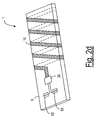
- Figure 2d is a diagrammatic representation illustrating the antenna being disposed on both sides of the substrate.
- Figure 2e is a diagrammatic representation illustrating a coil-like antenna.
- Figure 3 is a block diagram illustrating a plurality of electrical components in the pre-processing module.
- Figure 4a is a block diagram illustrating the connection between the integrated digital broadcast reception system and a common part of the mobile phone.
- Figure 4b is a block diagram illustrating the connection between the integrated analog broadcast reception system and a common part of the mobile phone.
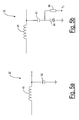
- Figure 5a is a circuit diagram illustrating a fixed band-tuning circuit.
- Figure 5b is a circuit diagram illustrating a variable band-tuning circuit.
- Figure 6a is a circuit diagram illustrating a signal amplifier circuit.
- Figure 6b is a circuit diagram illustrating a signal amplifier circuit having a gain control element.
- Figure 7 is a circuit diagram illustrating an impedance matching circuit.
-
- The basic components of the integrated FM/digital
broadcast reception system 1, according to the present invention, include anantenna 10 directly connected to apre-processing module 20. Theantenna 10 and pre-processingmodule 20 are disposed on asubstrate 5, as shown in Figures 2a and 2b. Theantenna 10 can be printed on thesubstrate 5 or etched out from aground plane 60 of a printed circuit board (PCB) or a printed wire board (PWB). As such, the integratedreception system 1 is easy to produce and install in a hand-held telecommunication device such as amobile phone 100, as shown in Figures 1a - 1c. - As shown in Figures 1 a - 1c, the
mobile phone 100 has a phone body orhousing 110, and achassis 120 on which some or all electronic telecommunication components are disposed. For example, a microprocessor or ASIC is usually disposed on thechassis 120, along with a display, a SIM card reader, memory, battery and so on. The chassis is not part of the invention. Thesubstrate 5 for accommodating theantenna 10 and thepre-processing module 20 can be an integral part of thechassis 120, as shown in Figure 1a. This means that theantenna 10 can be printed on the chassis together with the connecting wires and other electrically conductive parts. Alternatively, theantenna 10 can be etched out from the ground plane of the chassis. - The
substrate 5 can also be a base material separate from the chassis, as shown in Figure 1b. In that case, theantenna 10 and thepre-processing module 20 are produced or assembled on thesubstrate 5, and thesubstrate 5 is then mechanically and electronically connected to thechassis 120 in a separate assembling process. Thesubstrate 5 can be a rigid piece of base material, as shown in Figure 1b. Alternatively, thesubstrate 5 can be a flexible piece of electrically non-conductive polymer or the like, as shown in Figure 1c. A flexible substrate, even with thepre-processing module 20 disposed thereon, can be folded (Figure 2c) or twisted to fit in some small extra space within thehousing 110. As shown in Figures 2a and 2b, asignal connector 50 is also provided so thatpre-processed signals 78 can be conveyed to thechassis 120 of themobile phone 100. Additionally, apower connector 52 is provided to bringpower 80 to thepre-processing module 20. As shown in Figure 2c, thesubstrate 5 is flexible such that it can be rolled up into a small volume. As shown in Figure 2d, theantenna 10 is wound around thesubstrate 5 to form a helix occupying both sides of thesubstrate 5. Similarly, theantenna 10 can be disposed on thesubstrate 5 as a coil and the like, as shown in Figure 2e. The objective of the present invention is to reduce the physical size or dimension of theantenna 10 and that of thesubstrate 5. If the frequency of the carrier waves is 88 MHz, then the wavelength of carrier waves is approximately 341 cm. With the present invention, the physical size of theantenna 10 and that of thesubstrate 5 can be made much smaller than the quarter-wavelength, or 85 cm (33.46 inches). - As shown in Figure 2a, the
pre-processing module 20 and theantenna 10 are disposed on thesame side 6 of thesubstrate 5. However, they can be disposed on different sides of thesubstrate 5, as shown in Figure 2b. As shown in Figure 2b, while theantenna 10 is provided on oneside 7 of thesubstrate 5, thepre-processing module 20 is mounted on theopposite side 6. Theantenna 10 can be etched out from an existingground plane 60 of thesubstrate 5. - The
pre-processing module 20 is disposed together with theantenna 10 on thesubstrate 5 so that band-tuning and active amplification can be carried out on the same substrate. An exemplary circuit of the pre-processing module is shown in Figure 3. As shown in Figure 3, in order to process received broadcast signals 84 (in radio frequency) from theantenna 10, thepre-processing module 20 includes a band-tuning circuit 22, anactive amplification circuit 24, and animpedance matching circuit 26. Preferably, theantenna 10 is tuned by the band-tuning circuit 22 so that theantenna 10 pre-selects all stations in the FM frequency band of 88-108 MHz. The band-tuned signals are denoted byreference numeral 86. Exemplary band-tuning circuits are shown in Figures 5a and 5b. An exemplaryactive amplification circuit 24 is shown in Figure 6a. The amplified signals are denoted byreference numeral 88. Theimpedance matching circuit 26 can simply be acapacitor 76, as shown in Figure 7. The output from thepre-processing module 20 is denoted byreference numeral 90. - The present invention advantageously makes use of existing components of a typical mobile phone. In a digital phone, as shown in Figure 4a, existing
components 200 that can be used for further processing thepre-processed signals 90 includes a digital signal processor (DSP) 210, aspeaker 220 and apower supply 230. For example, thesignals 90 are directly fed to an analog-to-digital converter (A/D) inside theDSP 210. TheDSP 210 is also used for channel selection and demodulation. Additionally, theDSP 210 can be used to generate a tuning voltage VT for band-tuning and a gain-control voltage VG to control the gain of theactive amplification circuit 24. The output 92 (in audio frequency) from theDSP 210 is then conveyed to thespeaker 220 to produce audible sound. Thepower supply 230 of themobile phone 100 can also be used to provide power Vcc to thepre-processing module 20. Preferably, the power Vcc is provided to thepre-processing module 20 only when themobile phone 100 is switched to the broadcast receiving mode. The power Vcc provided to thepre-processing module 20 is turned off by aswitch 240 during a call. The power Vcc provided to thepre-processing module 20 can also be switched off when themobile phone 100 is not used to receive broadcast signals to save power. - When the
mobile phone 100 is used to receive analog broadcast signals,additional components 300 are needed. As shown in Figure 4b, achannel selection tuner 310 allows a user to select a channel from the pre-processed signals 90. The radio frequency signals 94, as selected by thechannel selection tuner 310, are down-converted intoaudio signals 96 by ademodulation module 320. As it is known in the art, thedemodulation module 320 may comprise a local oscillator, mixer, one or more intermediate stages, demodulator and so forth. The audio frequency signals 96 are further processed by anamplifier 212 before being conveyed to thespeaker 220. Theamplifier 212, thespeaker 220 and thepower supply 230 are theaudio components 202 commonly found in amobile phone 100. As shown in Figure 4b, the channel is selected by applying a tuning voltage VT, via anexternal control 330. Preferably, the gain control voltage VG is provided by an automatic gain control unit (AGC), which is not shown. The band-tuning voltage VT, however, should be provided in the manufacturing process. - It is possible that an antenna of a selected size can be used with a resonance circuit to select the frequency band. For example, an LC circuit, as shown in Figure 5a, having a fixed
inductor 60 and a fixedcapacitor 62 can be used for band-tuning. However, antennas in different mobile phones can be of different sizes. Thus, these antennas must be tuned for band selection. For that purpose, it is possible to add avaricap 64 in the LC circuit, as shown in Figure 5b so that antennas of different sizes can be used with asimilar pre-processing module 20. In order to tune theantenna 10, a band-tuning voltage VT, generated by theDSP 210, is fed to thevaricap 64 via aresistor 66, as shown in Figure 5b. - Figure 6a shows an exemplary
signal amplification circuit 24. As shown in Figure 6a, anFET 72 and tworesistors
denotes input impedance of the amplifier. If necessary, an output impedance Zout is provided with acapacitor 76, as shown in Figure 7, such that Zin >> Zout. It is preferred that thecapacitor 76 is located within theDSP 210. Because the output impedance Zout of the FET stage depends also on thedrain resistor 74, it is possible to vary thedrain resistor 74 to adjust the output impedance Zout . Furthermore, it is possible to vary the amplification factor or gain of thesignal amplification circuit 24 by feeding the gain-control voltage VG to acapacitor 71 connected between thegate resistor 70 and the ground, as shown in Figure 6b. - The
additional components 300 can be disposed on thesubstrate 5, or on thechassis 120. - In summary, the present invention integrates an FM broadcast reception system inside a hand-held telecommunication device, such as a mobile phone. The FM antenna is not protruding outside of the phone body. The present invention makes reception of FM broadcast possible without using any external parts. The antenna is lightweight and cost-effective. By disposing the antenna on a substrate inside the phone body, the necessary mechanical and electrical interfacing to the phone is greatly simplified. As it is known, the FM broadcast uses the frequency range of 88 MHz -108 MHz, so as the basic digital broadcasting system. The physical size of the antenna and the substrate of the present invention is much smaller than the quarter-wavelength of the received signals in that frequency range. However, the present invention is also applicable to other frequency ranges as well. For example, the internal broadcast reception system for the present invention is also used to receive the broadcast in the 53 MHz - 99 MHz, or the digital broadcast around 200 MHz.
- Thus, although the invention has been described with respect to a preferred embodiment thereof, it will be understood by those skilled in the art that the foregoing and various other changes, omissions and deviations in the form and detail thereof may be made without departing from the spirit and scope of this invention.
- An integrated reception system for use in a mobile phone for receiving FM/digital broadcast signals. The reception system, which is installed within the phone body, includes a substrate, an antenna having a meandering pattern disposed on the substrate for receiving the broadcast signals, and a pre-processing module disposed on the substrate and connected to the antenna for pre-processing the received signals. The pre-processing module may include a passive filtering network for band-tuning, and an active amplifier for amplifying the received signals from the antenna. The mobile phone has components for converting the received signals into audio signals to produce audio sound.
Claims (40)
- An integrated broadcast reception system for use in a hand-held telecommunication device for receiving broadcast signals, wherein the hand-held telecommunication device has a device body, the reception system comprising:an electrically non-conductive substrate located inside the device body;an electrically conductive element, disposed on the substrate, for receiving the broadcast signals; anda signal processing module disposed on the substrate adjacent and electronically connected to one end of the electrically conductive element, responsive to the received signals, for processing the received signals.
- The broadcast reception system of claim 1, wherein the hand-held telecommunication device includes a chassis within the device body for disposing telecommunication components, and wherein the electrically non-conductive substrate is a part of the chassis.
- The broadcast reception system of claim 1, wherein the electrically non-conductive substrate is made of a rigid material.
- The broadcast reception system of claim 1, wherein the electrically non-conductive substrate is made of a flexible material.
- The broadcast reception system of claim 1, wherein the electrically conductive element has a meandering shape for reducing the size of the electrically non-conductive substrate.
- The broadcast reception system of claim 1, wherein the physical length of the electrically conductive element is substantially smaller than a quarter-wavelength of the received signals.
- The broadcast reception system of claim 1, wherein the physical length of the electrically non-conductive substrate is substantially smaller than a quarter-wavelength of the received signals.
- The broadcast reception system of claim 1, wherein the electrically conductive element is disposed on one side of the electrically non-conductive substrate.
- The broadcast reception system of claim 1, wherein the electrically conductive element is disposed on both sides of the electrically non-conductive substrate.
- The broadcast reception system of claim 1, wherein the electrically conductive element is wound around the electrically non-conductive substrate.
- The broadcast reception system of claim 4, wherein the electrically non-conductive substrate is made into a compact shape to be fitted in the device body.
- The broadcast reception system of claim 1, wherein the electrically conductive element is a wound coil.
- The broadcast reception system of claim 1, wherein the electrically conductive element has a helical shape.
- The broadcast reception system of claim 1, wherein the broadcast signals are frequency-modulated signals.
- The broadcast reception system of claim 14, wherein the broadcast signals are substantially in a frequency range of 88 MHz - 105 MHz.
- The broadcast reception system of claim 1, wherein the broadcast signals are digital broadcast signals.
- The broadcast reception system of claim 16, wherein the broadcast signals are substantially in a frequency range of 88 MHz - 105 MHz.
- The broadcast reception system of claim 16, wherein the broadcast signals are substantially in a frequency of 200 MHz.
- The broadcast reception system of claim 1, wherein the signal processing module comprises an active circuit, responsive to the received signals, for providing amplified signals.
- The broadcast reception system of claim 19, wherein the active circuit is controllable for adjusting a gain of the amplified signals.
- The broadcast reception system of claim 1, wherein the signal processing module comprises a band-tuning circuit, responsive to the received signals, for selecting a broadcasting frequency band for providing band-tuned signals.
- The broadcast reception system of claim 21, wherein the signal processing module further comprises an amplification device, responsive to the band-tuned signals, for providing amplified signals.
- A mobile phone capable of receiving broadcast signals, comprising:a housing;an internal broadcast reception system, disposed within the housing, wherein the reception system comprises:an electrically non-conductive substrate located inside the device body;an electrically conductive element, disposed on the substrate, for receiving the broadcast signals; anda signal processing module disposed on the substrate adjacent and electronically connected to one end of the electrically conductive element, responsive to the received signals, for providing pre-processed signals; andmeans, responsive to the pre-processed signals, for providing audio signals indicative of the broadcast signals.
- The mobile phone of claim 23, wherein the broadcast signals are substantially in a frequency range of 88 MHz - 105 MHz.
- The mobile phone of claim 23, wherein the broadcast signals are substantially in a frequency range of 53 MHz - 99 MHz.
- The mobile phone of claim 23, wherein the broadcast signals are digital broadcast signals.
- The mobile phone of claim 26, wherein the broadcast signals are in a frequency range around 200 MHz.
- The mobile phone of claim 26, wherein said providing means comprises a converter, responsive to the pre-processed signals, for providing signals in a digital form, wherein the audio signals are provided based on the signals in the digital form.
- The mobile phone of claim 26, wherein said providing means comprises further means for controlling the signal processing module for selecting a broadcasting frequency band, wherein the pre-processed signals are indicative of the broadcast signals of the selected frequency band.
- The mobile phone of claim 29, wherein said providing means comprises further means for selecting a broadcast channel in the broadcasting frequency band.
- The mobile phone of claim 26, wherein said providing means comprises further means for selecting a broadcast channel in a broadcast frequency band.
- The mobile phone of claim 23, wherein the broadcast signals are frequency-modulated signals.
- The mobile phone of claim 32, wherein the signal processing module comprises a band-tuning circuit, responsive to the received signals, for selecting a broadcasting frequency band.
- The mobile phone of claim 33, wherein the selected frequency band is substantially within a range of 88 MHz and 108 MHz.
- The mobile phone of claim 32, wherein said providing means comprises a tuning circuit for selecting a broadcast channel in a broadcast frequency band for providing further signals indicative of the broadcast of the selected channel.
- The mobile phone of claim 35, wherein said providing means further comprises a converter, responsive to the further signals, for providing the audio signals.
- The mobile phone of claim 23, further comprising a chassis within the housing for disposing said providing means, wherein the hand-held telecommunication device includes a chassis, and wherein the electrically non-conductive substrate is a part of the chassis.
- The mobile phone of claim 37, wherein the electrically non-conductive substrate is made of a rigid material mechanically linked to the chassis and the integrated broadcast reception system is electronically linked to the chassis.
- The mobile phone of claim 37, wherein the electrically non-conductive substrate is made of a flexible material mechanically linked to the chassis and the integrated broadcast reception system is electronically linked to the chassis.
- The mobile phone of claim 23, wherein the electrically conductive element has a meandering or wound shape for reducing the size of the electrically non-conductive substrate.
Applications Claiming Priority (2)
| Application Number | Priority Date | Filing Date | Title |
|---|---|---|---|
| US954619 | 2001-09-17 | ||
| US09/954,619 US7039437B2 (en) | 2001-09-17 | 2001-09-17 | Internal broadcast reception system for mobile phones |
Publications (2)
| Publication Number | Publication Date |
|---|---|
| EP1294046A2 true EP1294046A2 (en) | 2003-03-19 |
| EP1294046A3 EP1294046A3 (en) | 2004-07-07 |
Family
ID=25495696
Family Applications (1)
| Application Number | Title | Priority Date | Filing Date |
|---|---|---|---|
| EP02018345A Ceased EP1294046A3 (en) | 2001-09-17 | 2002-08-14 | Internal broadcast reception system for mobile phones |
Country Status (3)
| Country | Link |
|---|---|
| US (1) | US7039437B2 (en) |
| EP (1) | EP1294046A3 (en) |
| CN (1) | CN1235428C (en) |
Cited By (7)
| Publication number | Priority date | Publication date | Assignee | Title |
|---|---|---|---|---|
| WO2004091233A1 (en) | 2003-04-09 | 2004-10-21 | Perlos Ab | An apparatus for signal reception |
| WO2005024997A1 (en) * | 2003-09-05 | 2005-03-17 | Lk Products Oy | Antenna structure for listening to radio broadcasts by a mobile station and a mobile station |
| EP1689021A1 (en) * | 2005-02-07 | 2006-08-09 | Sony Ericsson Mobile Communications AB | In-built FM antenna |
| EP2056395A1 (en) | 2007-11-05 | 2009-05-06 | Laird Technologies AB | Antenna device and portable radio communication device comprising such antenna device |
| EP1625586A4 (en) * | 2003-05-20 | 2010-05-12 | Enter Tech Co Ltd | Portable karaoke system |
| WO2010086208A1 (en) * | 2009-01-30 | 2010-08-05 | Cambridge Silicon Radio Limited | Internal fm antenna |
| US7856259B2 (en) | 2007-08-29 | 2010-12-21 | Sony Ericsson Mobile Communications Ab | In-built FM antenna |
Families Citing this family (22)
| Publication number | Priority date | Publication date | Assignee | Title |
|---|---|---|---|---|
| US6928308B2 (en) * | 2002-06-08 | 2005-08-09 | Micro Mobio Corporation Taiwan Branch (Usa) | Mobile phone hand-free extension device |
| JPWO2004047223A1 (en) * | 2002-11-18 | 2006-03-23 | 株式会社ヨコオ | Multi-band antenna |
| JP2004266407A (en) * | 2003-02-28 | 2004-09-24 | Hitachi Ltd | Mobile terminal adapter, mobile terminal, and method for selectively mounting mobile terminal adapter |
| KR100672460B1 (en) | 2004-11-17 | 2007-01-24 | 엘지전자 주식회사 | Frequency tuning device and method therefor |
| US20070021156A1 (en) * | 2005-07-19 | 2007-01-25 | Hoong Chow T | Compact radio communications device |
| US7383060B2 (en) * | 2005-09-06 | 2008-06-03 | Darts Technologies Corp. | Mobile phone with FM antenna |
| JP2007243863A (en) * | 2006-03-13 | 2007-09-20 | Niigata Seimitsu Kk | Portable device with am radio |
| TW200824309A (en) * | 2006-11-20 | 2008-06-01 | Lite On Technology Corp | Receiver of a FM system |
| WO2009048614A1 (en) | 2007-10-12 | 2009-04-16 | Powerwave Technologies, Inc. | Omni directional broadband coplanar antenna element |
| CN101610306B (en) * | 2008-06-16 | 2012-08-29 | 鸿富锦精密工业(深圳)有限公司 | Radio communication device |
| US20100231461A1 (en) * | 2009-03-13 | 2010-09-16 | Qualcomm Incorporated | Frequency selective multi-band antenna for wireless communication devices |
| CN102656744A (en) * | 2009-12-17 | 2012-09-05 | 莱尔德技术股份有限公司 | Antenna arrangement and portable radio communication device therefore |
| CN101917562A (en) * | 2010-07-23 | 2010-12-15 | 中兴通讯股份有限公司 | A mobile TV terminal and its implementation method |
| CN101917563A (en) * | 2010-07-23 | 2010-12-15 | 中兴通讯股份有限公司 | A mobile TV terminal and its implementation method |
| CN102637946B (en) * | 2011-02-14 | 2015-06-03 | 中兴通讯股份有限公司 | Frequency modulation (FM) antenna implementation device and mobile terminal |
| DE102014106815B4 (en) * | 2014-05-14 | 2024-01-18 | Infineon Technologies Ag | Communication module |
| KR102138910B1 (en) * | 2014-06-23 | 2020-07-28 | 삼성전자주식회사 | Electronic device with ring type antenna |
| US10128574B2 (en) * | 2015-11-24 | 2018-11-13 | Aac Acoustic Technologies (Shenzhen) Co., Ltd | Antenna tuning assembly and mobile communication apparatus using same |
| US10957972B2 (en) | 2018-05-29 | 2021-03-23 | Team Ip Holdings, Llc | Audio device |
| US11258165B2 (en) * | 2018-12-31 | 2022-02-22 | Qualcomm Incorporated | Asymmetric antenna structure |
| CN113964514B (en) * | 2021-10-26 | 2024-10-29 | 维沃移动通信有限公司 | Electronic devices |
| US20250047004A1 (en) * | 2023-07-31 | 2025-02-06 | The Trustees of the California State University | Helical antennae, along with their methods of use and production |
Citations (2)
| Publication number | Priority date | Publication date | Assignee | Title |
|---|---|---|---|---|
| JPH09130132A (en) * | 1995-11-01 | 1997-05-16 | S I I R D Center:Kk | Small-sized antenna |
| JPH09199919A (en) * | 1996-01-23 | 1997-07-31 | Yokowo Co Ltd | Antenna system |
Family Cites Families (11)
| Publication number | Priority date | Publication date | Assignee | Title |
|---|---|---|---|---|
| US4001696A (en) * | 1974-08-02 | 1977-01-04 | George Louis Bannerman | Electronic antenna |
| US4409688A (en) * | 1979-04-30 | 1983-10-11 | Masco Corporation Of Indiana | Processor controlled, scanning radio receiver including future code developing means |
| JPS59169207A (en) * | 1983-03-16 | 1984-09-25 | Mitsubishi Electric Corp | Antenna feeding circuit |
| FR2624656B1 (en) * | 1987-12-10 | 1990-05-18 | Centre Nat Etd Spatiales | PROPELLER-TYPE ANTENNA AND ITS MANUFACTURING METHOD |
| JP3082447B2 (en) * | 1992-06-25 | 2000-08-28 | ソニー株式会社 | Digital broadcast receiver |
| JP2586441B2 (en) * | 1994-07-27 | 1997-02-26 | 日本電気株式会社 | Mobile phone |
| SE511295C2 (en) * | 1997-04-30 | 1999-09-06 | Moteco Ab | Antenna for radio communication device |
| US6028567A (en) * | 1997-12-10 | 2000-02-22 | Nokia Mobile Phones, Ltd. | Antenna for a mobile station operating in two frequency ranges |
| JPH11274958A (en) * | 1998-03-23 | 1999-10-08 | Pioneer Electron Corp | Digital broadcast receiver |
| US6046703A (en) * | 1998-11-10 | 2000-04-04 | Nutex Communication Corp. | Compact wireless transceiver board with directional printed circuit antenna |
| GB2358991B (en) | 1999-09-14 | 2002-02-13 | Motorola Inc | Wireless radio frequency peripheral interface for a cellular communication device |
-
2001
- 2001-09-17 US US09/954,619 patent/US7039437B2/en not_active Expired - Lifetime
-
2002
- 2002-08-14 EP EP02018345A patent/EP1294046A3/en not_active Ceased
- 2002-09-17 CN CN02142661.9A patent/CN1235428C/en not_active Expired - Fee Related
Patent Citations (2)
| Publication number | Priority date | Publication date | Assignee | Title |
|---|---|---|---|---|
| JPH09130132A (en) * | 1995-11-01 | 1997-05-16 | S I I R D Center:Kk | Small-sized antenna |
| JPH09199919A (en) * | 1996-01-23 | 1997-07-31 | Yokowo Co Ltd | Antenna system |
Cited By (7)
| Publication number | Priority date | Publication date | Assignee | Title |
|---|---|---|---|---|
| WO2004091233A1 (en) | 2003-04-09 | 2004-10-21 | Perlos Ab | An apparatus for signal reception |
| EP1625586A4 (en) * | 2003-05-20 | 2010-05-12 | Enter Tech Co Ltd | Portable karaoke system |
| WO2005024997A1 (en) * | 2003-09-05 | 2005-03-17 | Lk Products Oy | Antenna structure for listening to radio broadcasts by a mobile station and a mobile station |
| EP1689021A1 (en) * | 2005-02-07 | 2006-08-09 | Sony Ericsson Mobile Communications AB | In-built FM antenna |
| US7856259B2 (en) | 2007-08-29 | 2010-12-21 | Sony Ericsson Mobile Communications Ab | In-built FM antenna |
| EP2056395A1 (en) | 2007-11-05 | 2009-05-06 | Laird Technologies AB | Antenna device and portable radio communication device comprising such antenna device |
| WO2010086208A1 (en) * | 2009-01-30 | 2010-08-05 | Cambridge Silicon Radio Limited | Internal fm antenna |
Also Published As
| Publication number | Publication date |
|---|---|
| EP1294046A3 (en) | 2004-07-07 |
| US7039437B2 (en) | 2006-05-02 |
| CN1235428C (en) | 2006-01-04 |
| US20030054855A1 (en) | 2003-03-20 |
| CN1409569A (en) | 2003-04-09 |
Similar Documents
| Publication | Publication Date | Title |
|---|---|---|
| US7039437B2 (en) | Internal broadcast reception system for mobile phones | |
| JP4574922B2 (en) | Multi-frequency band branch antenna for wireless communication equipment | |
| EP2258049B1 (en) | Apparatus comprising a broadcast receiver circuit and provided with an antenna | |
| JP4523211B2 (en) | Folding dual frequency band antenna for wireless communication device | |
| KR100592209B1 (en) | Multifrequency Antenna | |
| US6707428B2 (en) | Antenna | |
| US6683570B2 (en) | Compact multi-band antenna | |
| JP2003505965A (en) | Flat dual frequency band antenna for wireless communication | |
| US6127979A (en) | Antenna adapted to operate in a plurality of frequency bands | |
| US6198943B1 (en) | Parasitic dual band matching of an internal looped dipole antenna | |
| EP1965502B1 (en) | Antenna device and portable radio communication device comprising such antenna device | |
| CN101682103A (en) | Antenna for mobile terminal unit | |
| JP4207641B2 (en) | Portable receiver | |
| US20050156805A1 (en) | Antenna and electronic device using same | |
| JP2008259039A (en) | Antenna device | |
| US7383060B2 (en) | Mobile phone with FM antenna | |
| US20060139227A1 (en) | Antenna device having enhanced reception sensitivity in wide bands | |
| KR20090038979A (en) | Antenna device of the terminal | |
| EP1689021B1 (en) | In-built FM antenna | |
| AU2008231724A1 (en) | Antenna | |
| WO2004091233A9 (en) | An apparatus for signal reception | |
| JPH10163734A (en) | Antenna device | |
| JPH0779467A (en) | Wrist watch type selective calling receiver | |
| KR20080041900A (en) | Active Antenna Using Dielectric Resonator | |
| JP2002111342A (en) | Antenna unit and receiver using the same |
Legal Events
| Date | Code | Title | Description |
|---|---|---|---|
| PUAI | Public reference made under article 153(3) epc to a published international application that has entered the european phase |
Free format text: ORIGINAL CODE: 0009012 |
|
| AK | Designated contracting states |
Kind code of ref document: A2 Designated state(s): AT BE BG CH CY CZ DE DK EE ES FI FR GB GR IE IT LI LU MC NL PT SE SK TR Designated state(s): AT BE BG CH CY CZ DE DK EE ES FI FR GB GR IE IT LI LU MC NL PT SE SK TR |
|
| AX | Request for extension of the european patent |
Extension state: AL LT LV MK RO SI |
|
| RIC1 | Information provided on ipc code assigned before grant |
Ipc: 7H 04H 1/00 B Ipc: 7H 04B 1/38 B Ipc: 7H 04B 1/16 B Ipc: 7H 01Q 23/00 B Ipc: 7H 01Q 1/08 B Ipc: 7H 01Q 1/24 B Ipc: 7H 01Q 1/36 B Ipc: 7H 01Q 1/38 A |
|
| PUAL | Search report despatched |
Free format text: ORIGINAL CODE: 0009013 |
|
| AK | Designated contracting states |
Kind code of ref document: A3 Designated state(s): AT BE BG CH CY CZ DE DK EE ES FI FR GB GR IE IT LI LU MC NL PT SE SK TR |
|
| AX | Request for extension of the european patent |
Extension state: AL LT LV MK RO SI |
|
| 17P | Request for examination filed |
Effective date: 20040805 |
|
| 17Q | First examination report despatched |
Effective date: 20050114 |
|
| AKX | Designation fees paid |
Designated state(s): DE FI FR GB NL SE |
|
| STAA | Information on the status of an ep patent application or granted ep patent |
Free format text: STATUS: THE APPLICATION HAS BEEN REFUSED |
|
| 18R | Application refused |
Effective date: 20121228 |