EP1293827A1 - Rotating processor for photographic material - Google Patents
Rotating processor for photographic material Download PDFInfo
- Publication number
- EP1293827A1 EP1293827A1 EP02018975A EP02018975A EP1293827A1 EP 1293827 A1 EP1293827 A1 EP 1293827A1 EP 02018975 A EP02018975 A EP 02018975A EP 02018975 A EP02018975 A EP 02018975A EP 1293827 A1 EP1293827 A1 EP 1293827A1
- Authority
- EP
- European Patent Office
- Prior art keywords
- drum
- solution
- photographic material
- chamber
- processing
- Prior art date
- Legal status (The legal status is an assumption and is not a legal conclusion. Google has not performed a legal analysis and makes no representation as to the accuracy of the status listed.)
- Withdrawn
Links
- 239000000463 material Substances 0.000 title claims description 18
- 238000000034 method Methods 0.000 claims description 18
- 239000007921 spray Substances 0.000 claims description 7
- 239000007788 liquid Substances 0.000 claims description 6
- 238000010438 heat treatment Methods 0.000 claims description 2
- 230000003134 recirculating effect Effects 0.000 claims 1
- 239000002699 waste material Substances 0.000 description 5
- XLYOFNOQVPJJNP-UHFFFAOYSA-N water Substances O XLYOFNOQVPJJNP-UHFFFAOYSA-N 0.000 description 4
- BQCADISMDOOEFD-UHFFFAOYSA-N Silver Chemical group [Ag] BQCADISMDOOEFD-UHFFFAOYSA-N 0.000 description 2
- 230000000694 effects Effects 0.000 description 2
- 230000005484 gravity Effects 0.000 description 2
- 238000012986 modification Methods 0.000 description 2
- 230000004048 modification Effects 0.000 description 2
- 229910052709 silver Inorganic materials 0.000 description 2
- 239000004332 silver Substances 0.000 description 2
- 239000000126 substance Substances 0.000 description 2
- 238000005406 washing Methods 0.000 description 2
- 238000009736 wetting Methods 0.000 description 2
- 230000004308 accommodation Effects 0.000 description 1
- 238000013019 agitation Methods 0.000 description 1
- 239000007844 bleaching agent Substances 0.000 description 1
- 238000001311 chemical methods and process Methods 0.000 description 1
- 230000001419 dependent effect Effects 0.000 description 1
- 238000001704 evaporation Methods 0.000 description 1
- 230000008020 evaporation Effects 0.000 description 1
- 238000005086 pumping Methods 0.000 description 1
Images

Classifications
-
- G—PHYSICS
- G03—PHOTOGRAPHY; CINEMATOGRAPHY; ANALOGOUS TECHNIQUES USING WAVES OTHER THAN OPTICAL WAVES; ELECTROGRAPHY; HOLOGRAPHY
- G03D—APPARATUS FOR PROCESSING EXPOSED PHOTOGRAPHIC MATERIALS; ACCESSORIES THEREFOR
- G03D5/00—Liquid processing apparatus in which no immersion is effected; Washing apparatus in which no immersion is effected
- G03D5/04—Liquid processing apparatus in which no immersion is effected; Washing apparatus in which no immersion is effected using liquid sprays
-
- G—PHYSICS
- G03—PHOTOGRAPHY; CINEMATOGRAPHY; ANALOGOUS TECHNIQUES USING WAVES OTHER THAN OPTICAL WAVES; ELECTROGRAPHY; HOLOGRAPHY
- G03D—APPARATUS FOR PROCESSING EXPOSED PHOTOGRAPHIC MATERIALS; ACCESSORIES THEREFOR
- G03D13/00—Processing apparatus or accessories therefor, not covered by groups G11B3/00 - G11B11/00
- G03D13/02—Containers; Holding-devices
- G03D13/04—Trays; Dishes; Tanks ; Drums
- G03D13/046—Drums; Films convolutely fixed on the side of the drum
Definitions
- the invention relates to the field of photographic processing, in particular to drum processors.
- Drum processors are well known apparatus for developing paper photographic prints.
- the drum is mounted and rotated so that its bottom edge dips into a tray of processing solution.
- the solution is carried around the periphery of the drum and returned to the tray.
- the paper to be processed is held against the top of the drum floating on this liquid film.
- the paper is normally held stationary by a fixed backing sheet.
- the longest length of paper that can be accommodated by this type of processing device is governed by the maximum length of the drum surface clear of solution. Longer lengths have to pass further around the drum but it has been found that when they pass through the solution tray they leave the drum surface and get lost. If the lengths of paper are guided through the solution and up the other side of the drum uneven processing can occur. These problems do not occur normally with processing sheets having a maximum length of 12 inches ( ⁇ 30.5 cm) but the diameter of the drum becomes excessive if a long length needs to be processed.
- This invention aims to reduce the diameter of drum type processors. This is especially useful when processing long lengths of paper or other photographic media.
- apparatus for processing photographic media including a rotatable drum housed within an enclosure chamber, the chamber having a first opening and a second opening, means, located at the first opening of the chamber, for applying processing solution to the surface of the drum and means for feeding and withdrawing the photographic media to and from the enclosure chamber and around the periphery of the drum, the sensitised side thereof facing the drum.
- the present invention further provides a method of processing photographic material comprising the steps of applying processing solution to the outer surface of a rotating drum to form a film of solution around a substantial part of the periphery thereof, the drum being housed in an enclosure chamber, feeding the media to be processed into the chamber and around the periphery of the drum to lie above the film of solution, the sensitised side of the media being in contact with the film of solution, and withdrawing the media from the chamber.
- the solution is re-circulated around the surface of the drum.
- the solution is fed into the top of the enclosure chamber as this provides gravity assisted wetting.
- the processing solution is preferably supplied to the top of the drum by pumping it from a drain sump at the bottom Less solution is required than by prior art processors.
- the application of solution can be controlled.
- the solution can be applied to both sides of the material.
- the processor is self loading and as it is smaller than those known in the prior art it requires less energy to heat and run. There are also less moving parts to the processor.
- the processor allows the solutions to be changed very easily to optimise the processing.
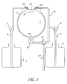
- Figure 1 is a schematic view of the general arrangement of the processor.
- a rotatable processing drum 1 is housed within a housing or enclosure chamber 2.
- the radius of the drum is such that the circumference is substantially the same as the length of photographic media to be processed.
- the surface of the drum is smooth.
- the enclosure chamber 2 is provided with an opening 22 at the upper side thereof for entry of the photographic media to be processed.
- the opening 22 can be located anywhere around the periphery of the enclosure chamber 2 but the method of the invention works best when the opening is at the top.
- a further opening 20 is provided at the bottom of the enclosure chamber 2.
- the gap between the outer surface of the processing drum 1 and the inner wall of the enclosure chamber 2 lies in the range of 1 mm to 200 mm for most of the circumference. The gap widens around the opening 22. The gap also widens at opening 20 so that a puddle of solution does not form.
- an external circulation loop 10 connects the top and bottom of the enclosure chamber 2 between opening 20 and opening-22.
- Application means such as a spray bar 23, is provided at the upper end of the loop 10, within the enclosure chamber 2.
- the circulation loop includes pump 9. This may be located at the bottom end of the loop.
- a valve arrangement 19 is also included in the loop. The valve 19 is in connection with a waste pipe 18. If the waste from each solution is to be kept separate, e.g. for silver bearing waste to be collected separately, valve 19 could be a manifold with separate waste pipes 18.
- a reservoir 4 is connected to the circulation loop 10 via pipe 6 and pump 8.
- the chemical solutions required for processing are stored in the reservoir 4.
- a separate reservoir 4, pipe 6 and pump 8 is required for each solution, i.e developer, bleach, fix, wash solution etc.. Only one is shown in Figure 1 for simplicity.
- a second reservoir 3 is connected via pipe 5 and pump 7 to the top of the enclosure chamber 2. Further wash solution is stored in reservoir 3.
- Application means, such as a spray bar 24, is provided at the end of pipe 5 which terminates within the upper part of enclosure chamber 2 at the other side of opening 22 from application means 23.
- reservoir 3 may be dispensed with if the application means 23 is modified to be able to apply solution to both the front and the back of the media. This modification could, for example, be by means of using a solenoid valve which allows the solutions to be applied either in front of or behind the opening 22.
- a fixed volume of processing solution is pumped out of reservoir 4 by pump 8.
- the volume should be excess to that required for the processing to allow for take up swell in the material being processed. Also it is preferable to have sufficient solution for re-circulation. This ensures the drum does not dry out during the process.
- the solution is pumped from the reservoir 4 into the circulation loop 10 and up to the opening 22 into enclosure chamber 2.
- the solution is applied to the surface of the drum 1 via spray bar 23. It is not necessary that the solution is sprayed. Application could be by other means, such as rollers, pads, a curtain of liquid, etc..
- the solution is applied to the drum just prior to where the photographic media, for example film, 14 is introduced. This could be anywhere around the drum but the invention works best when this is at the top of the enclosure chamber.
- the wetting is then assisted by gravity.
- the solution is drawn around the drum by the rotation of the drum. In operation the drum 1 is rotating continuously.
- the outer surface of the drum is continuously wetted by the processing solution.
- the surface speed of the drum is dependent on the viscosity of the solution being applied.
- the media is supported by the liquid bearing formed on the surface of the drum.
- the solution exits the enclosure chamber 2 via the opening 20 at the lower end of the enclosure and into the circulation loop 10.
- the solution is circulated around the loop and back through the enclosure chamber throughout the processing operation by pump 9.
- the film 14 is loaded.
- the film is loaded by means of drive rollers, not shown. As the drum rotates faster than the film is fed on by the drive rollers it is possible for the processing solution to be applied simultaneously as the film is fed and still have the same effect. The film is fed relatively slowly in comparison with the speed of the drum.
- the rotation of the drum tries to pull the film out of the cassette. However the end of the film may remain attached to its cartridge as it is held in position by the rollers. Once the film is loaded it does not move further.
- wash water for washing the back of the film is applied from the spray applicator 24.
- Wash water for washing the front of the film is applied from spray applicator 23, to the sensitised side of the film.
- the drum is heated. In this case excess solution will be required due to evaporation.
- the drum can be heated-directly or the whole enclosure chamber can be heated.
- the drum may be heated by having a hot liquid contained therein. Due to the thermal mass of the drum the processing solutions are heated almost instantaneously as they come into contact with the drum. This improves the life of the chemical solutions as they are not sitting in tanks at the operating temperature prior to use. No pre-heating of the solution is required.
- timing of each of the process steps can be varied allowing for accommodation of under and over exposure. This information can be found by, for example, the magnetic strip of an APS film or from an infra-red detector in the processor which can identify silver development.
- the invention can be used with conventional development, RX development, with negative film, transparency film etc.
- the invention is applicable to all photographic media, for example, APS film, 35 mm film, 120 mm film or paper.
- the invention can also be used with thicker, stiff webs of material. If these stiffer webs of material are reluctant to follow the curvature of the drum a flexible cover 25 can be provided and positioned around the drum. This is illustrated in Figure 3.
Landscapes
- Physics & Mathematics (AREA)
- General Physics & Mathematics (AREA)
- Photographic Processing Devices Using Wet Methods (AREA)
- Photographic Developing Apparatuses (AREA)
Abstract
Description
- The invention relates to the field of photographic processing, in particular to drum processors.
- Drum processors are well known apparatus for developing paper photographic prints. In this known apparatus the drum is mounted and rotated so that its bottom edge dips into a tray of processing solution. As the drum rotates the motion thereof lifts up the solution on to its surface. The solution is carried around the periphery of the drum and returned to the tray. The paper to be processed is held against the top of the drum floating on this liquid film. The paper is normally held stationary by a fixed backing sheet.
- The longest length of paper that can be accommodated by this type of processing device is governed by the maximum length of the drum surface clear of solution. Longer lengths have to pass further around the drum but it has been found that when they pass through the solution tray they leave the drum surface and get lost. If the lengths of paper are guided through the solution and up the other side of the drum uneven processing can occur. These problems do not occur normally with processing sheets having a maximum length of 12 inches (∼30.5 cm) but the diameter of the drum becomes excessive if a long length needs to be processed.
- This invention aims to reduce the diameter of drum type processors. This is especially useful when processing long lengths of paper or other photographic media.
- According to the present invention there is provided apparatus for processing photographic media including a rotatable drum housed within an enclosure chamber, the chamber having a first opening and a second opening, means, located at the first opening of the chamber, for applying processing solution to the surface of the drum and means for feeding and withdrawing the photographic media to and from the enclosure chamber and around the periphery of the drum, the sensitised side thereof facing the drum.
- The present invention further provides a method of processing photographic material comprising the steps of applying processing solution to the outer surface of a rotating drum to form a film of solution around a substantial part of the periphery thereof, the drum being housed in an enclosure chamber, feeding the media to be processed into the chamber and around the periphery of the drum to lie above the film of solution, the sensitised side of the media being in contact with the film of solution, and withdrawing the media from the chamber.
- Preferably the solution is re-circulated around the surface of the drum.
- Preferably the solution is fed into the top of the enclosure chamber as this provides gravity assisted wetting.
- This invention overcomes the excessive diameter required by known processors. The processing solution is preferably supplied to the top of the drum by pumping it from a drain sump at the bottom Less solution is required than by prior art processors. The application of solution can be controlled. The solution can be applied to both sides of the material. The processor is self loading and as it is smaller than those known in the prior art it requires less energy to heat and run. There are also less moving parts to the processor.
- The processor allows the solutions to be changed very easily to optimise the processing.
- It is advantageous to have the solution run around the circumference of the drum.
- The invention will now be described, by way of example, with reference to the accompanying drawings, in which:
- Figure 1 is a schematic view of a processor according to the invention;
- Figure 2 is a close up view of the top of the processor; and
- Figure 3 is a schematic view of a second embodiment of a processor according to the invention.
-
- Figure 1 is a schematic view of the general arrangement of the processor.
- A
rotatable processing drum 1 is housed within a housing orenclosure chamber 2. The radius of the drum is such that the circumference is substantially the same as the length of photographic media to be processed. The surface of the drum is smooth. Theenclosure chamber 2 is provided with anopening 22 at the upper side thereof for entry of the photographic media to be processed. The opening 22 can be located anywhere around the periphery of theenclosure chamber 2 but the method of the invention works best when the opening is at the top. Afurther opening 20 is provided at the bottom of theenclosure chamber 2. The gap between the outer surface of theprocessing drum 1 and the inner wall of theenclosure chamber 2 lies in the range of 1 mm to 200 mm for most of the circumference. The gap widens around the opening 22. The gap also widens at opening 20 so that a puddle of solution does not form. - In the embodiment illustrated an
external circulation loop 10 connects the top and bottom of theenclosure chamber 2 between opening 20 and opening-22. Application means, such as aspray bar 23, is provided at the upper end of theloop 10, within theenclosure chamber 2. This is shown in more detail in Figure 3. The circulation loop includes pump 9. This may be located at the bottom end of the loop. Avalve arrangement 19 is also included in the loop. Thevalve 19 is in connection with awaste pipe 18. If the waste from each solution is to be kept separate, e.g. for silver bearing waste to be collected separately,valve 19 could be a manifold withseparate waste pipes 18. - A
reservoir 4 is connected to thecirculation loop 10 viapipe 6 andpump 8. The chemical solutions required for processing are stored in thereservoir 4. Aseparate reservoir 4,pipe 6 andpump 8 is required for each solution, i.e developer, bleach, fix, wash solution etc.. Only one is shown in Figure 1 for simplicity. Asecond reservoir 3 is connected viapipe 5 and pump 7 to the top of theenclosure chamber 2. Further wash solution is stored inreservoir 3. Application means, such as aspray bar 24, is provided at the end ofpipe 5 which terminates within the upper part ofenclosure chamber 2 at the other side of opening 22 from application means 23. - Two reservoirs of wash solution are required in this embodiment in order to wash both the front and the back of the media being processed. Alternatively
reservoir 3 may be dispensed with if the application means 23 is modified to be able to apply solution to both the front and the back of the media. This modification could, for example, be by means of using a solenoid valve which allows the solutions to be applied either in front of or behind theopening 22. - In operation a fixed volume of processing solution is pumped out of
reservoir 4 bypump 8. The volume should be excess to that required for the processing to allow for take up swell in the material being processed. Also it is preferable to have sufficient solution for re-circulation. This ensures the drum does not dry out during the process. - The solution is pumped from the
reservoir 4 into thecirculation loop 10 and up to theopening 22 intoenclosure chamber 2. The solution is applied to the surface of thedrum 1 viaspray bar 23. It is not necessary that the solution is sprayed. Application could be by other means, such as rollers, pads, a curtain of liquid, etc.. The solution is applied to the drum just prior to where the photographic media, for example film, 14 is introduced. This could be anywhere around the drum but the invention works best when this is at the top of the enclosure chamber. The wetting is then assisted by gravity. The solution is drawn around the drum by the rotation of the drum. In operation thedrum 1 is rotating continuously. The outer surface of the drum is continuously wetted by the processing solution. The surface speed of the drum is dependent on the viscosity of the solution being applied. The media is supported by the liquid bearing formed on the surface of the drum. The solution exits theenclosure chamber 2 via theopening 20 at the lower end of the enclosure and into thecirculation loop 10. The solution is circulated around the loop and back through the enclosure chamber throughout the processing operation by pump 9. Once the drum is wetted with the processing solution thefilm 14 is loaded. The film is loaded by means of drive rollers, not shown. As the drum rotates faster than the film is fed on by the drive rollers it is possible for the processing solution to be applied simultaneously as the film is fed and still have the same effect. The film is fed relatively slowly in comparison with the speed of the drum. - It can be seen in Figure 2 that the solution is fed between the film and the drum. As the
film 14 enters into the enclosure chamber it passes right around the circumference of thedrum 1, floating on the solution. The film is fed in with the sensitised surface towards the drum. The film is kept on the drum by attraction to the solution, which lies between the drum and the film. This is a distinct advantage over the prior art where the media passes through a reservoir of solution and would often fall off. The relative motion between the drum and the film causes agitation. - It is possible to feed the
film 14 onto the drum at an angle such that a spiral is formed. This would further reduce the diameter of the drum required for processing although the width would have to increase. In this case it would be necessary to ensure that thespray applicator 23 covers the whole width of the drum. - The rotation of the drum tries to pull the film out of the cassette. However the end of the film may remain attached to its cartridge as it is held in position by the rollers. Once the film is loaded it does not move further.
- At no time is there sufficient solution in the system to form a puddle of solution at the lower part of the enclosure chamber. The system is drained between each processing solution by opening the
valve 19 and allowing the solution to pass through to thewaste pipe 18. The next solution required by the process is then fed into thecirculation loop 10 from thenext reservoir 4 and thus onto thedrum 1. This is done quickly and the drum does not dry out between solutions. The drum continues to rotate with the film floating on the residue of solution. - After the film has been processed it needs to be washed. It can be seen from Figure 4 that in this embodiment the wash water for washing the back of the film is applied from the
spray applicator 24. Wash water for washing the front of the film is applied fromspray applicator 23, to the sensitised side of the film. Once the film has been washed the drive rollers are reversed and the film is unloaded from the processor. It is possible to continue supplying wash water as the film is removed. Wash water could also be applied directly to the surface of the drum between films. - Preferably the drum is heated. In this case excess solution will be required due to evaporation. The drum can be heated-directly or the whole enclosure chamber can be heated. The drum may be heated by having a hot liquid contained therein. Due to the thermal mass of the drum the processing solutions are heated almost instantaneously as they come into contact with the drum. This improves the life of the chemical solutions as they are not sitting in tanks at the operating temperature prior to use. No pre-heating of the solution is required.
- There are no fixed path lengths in the processor. It is therefore possible to vary the timing of each of the process steps to optimise the processing of the media. The timing can be varied allowing for accommodation of under and over exposure. This information can be found by, for example, the magnetic strip of an APS film or from an infra-red detector in the processor which can identify silver development.
- It is easy to vary the chemical process because there are no fixed tanks. The invention can be used with conventional development, RX development, with negative film, transparency film etc.
- The invention is applicable to all photographic media, for example, APS film, 35 mm film, 120 mm film or paper. The invention can also be used with thicker, stiff webs of material. If these stiffer webs of material are reluctant to follow the curvature of the drum a
flexible cover 25 can be provided and positioned around the drum. This is illustrated in Figure 3. - It is possible for the processor to work continuously, i.e. one film after another.
- The invention has been described in detail with reference to preferred embodiments thereof. It will be understood by those skilled in the art that variations and modifications can be effected within the scope of the invention.
Claims (22)
- Apparatus for processing photographic media including a rotatable drum housed within an enclosure chamber, the chamber having a first opening and a second opening, means, located at the first opening of the chamber, for applying processing solution to the surface of the drum and means for feeding and withdrawing the photographic media to and from the enclosure chamber and around the periphery of the drum, the sensitised side thereof facing the drum.
- Apparatus as claimed in claim 1 including a circulation system external to the chamber for circulating the solution from the second opening to the first opening for re-application to the surface of the drum.
- Apparatus as claimed in claim 1, or 2 wherein means for applying wash solution is located at the first opening of the chamber.
- Apparatus as claimed in claim 1, 2 or 3 wherein the first opening of the enclosure chamber is located at the upper half thereof.
- Apparatus as claimed in any of claims 1 to 4 wherein solution is applied by spray means.
- Apparatus as claimed in any of claims 1 to 4 wherein solution is applied by roller means.
- Apparatus as claimed in any of claims 1 to 4 wherein solution is applied by means of pads.
- Apparatus as claimed in any preceding claim including means for heating the rotatable drum.
- Apparatus as claimed in claim 8 wherein the drum contains a heated liquid.
- A method of processing photographic material comprising the steps of applying processing solution to the outer surface of a rotating drum to form a film of solution around a substantial part of the periphery thereof, the drum being housed in an enclosure chamber, feeding the media to be processed into the chamber and around the periphery of the drum to lie above the film of solution, the sensitised side of the media being in contact with the film of solution, and withdrawing the media from the chamber.
- A method as claimed in claim 10 including the step of recirculating the solution around the surface of the drum.
- A method of processing photographic material as claimed in claim 10 or 11 wherein wash solution is applied to the media prior to withdrawal from the chamber.
- A method of processing photographic material as claimed in claim 10, 11 or 12 wherein solution is applied to the top half of the drum.
- A method of processing photographic material as claimed in any of claims 10 to 13 wherein the media is fed onto the periphery of the drum at an angle to form a spiral.
- A method of processing photographic material as claimed in any of claims 10 to 14 wherein more than one processing solution is applied serially to the outer surface of the drum, the previous solution being drained from the enclosure chamber before the next is applied.
- A method of processing photographic material as claimed in any of claims 10 to 15 wherein the solution is sprayed onto the drum.
- A method of processing photographic material as claimed in any of claims 10 to 15 wherein the solution is applied to the drum by means of rollers.
- A method of processing photographic material as claimed in any of claims 10 to 15 wherein the solution is applied to the drum by means of pads.
- A method of processing photographic material as claimed in any of claims 10 to 18 wherein the media is washed simultaneously as it is withdrawn.
- A method of processing photographic material as claimed in any of claims 10 to 19 wherein the rotatable drum is heated, the solution being heated on contact with the surface of the drum.
- A method of processing photographic material as claimed in claim 20 wherein the drum is heated by hot air.
- A method of processing photographic material as claimed in claim 20 wherein the drum is heated by a hot liquid contained therein.
Applications Claiming Priority (2)
| Application Number | Priority Date | Filing Date | Title |
|---|---|---|---|
| GBGB0122457.5A GB0122457D0 (en) | 2001-09-18 | 2001-09-18 | Rotating processor |
| GB0122457 | 2001-09-18 |
Publications (1)
| Publication Number | Publication Date |
|---|---|
| EP1293827A1 true EP1293827A1 (en) | 2003-03-19 |
Family
ID=9922252
Family Applications (1)
| Application Number | Title | Priority Date | Filing Date |
|---|---|---|---|
| EP02018975A Withdrawn EP1293827A1 (en) | 2001-09-18 | 2002-08-26 | Rotating processor for photographic material |
Country Status (4)
| Country | Link |
|---|---|
| US (1) | US6719465B2 (en) |
| EP (1) | EP1293827A1 (en) |
| JP (1) | JP2003107651A (en) |
| GB (1) | GB0122457D0 (en) |
Families Citing this family (1)
| Publication number | Priority date | Publication date | Assignee | Title |
|---|---|---|---|---|
| US7173254B2 (en) * | 2004-05-19 | 2007-02-06 | Light Sources, Inc. | Compact germicidal lamp having multiple wavelengths |
Citations (5)
| Publication number | Priority date | Publication date | Assignee | Title |
|---|---|---|---|---|
| US3709138A (en) * | 1971-05-21 | 1973-01-09 | L Brasher | Photographic print processing apparatus |
| US3727535A (en) * | 1970-09-25 | 1973-04-17 | R Streeter | Photographic processing apparatus |
| DE3102074A1 (en) * | 1981-01-23 | 1982-08-19 | Jobo Labortechnik Gmbh & Co Kg, 5270 Gummersbach | Device for developing photo material having a cylindrical drum which is driven to rotate |
| US5692188A (en) * | 1996-01-11 | 1997-11-25 | Watts; Todd A. | System for processing and washing photographic images |
| US6091480A (en) * | 1997-07-17 | 2000-07-18 | 3M Innovative Properties Company | Film removal mechanism for use with a thermal drum processor system |
Family Cites Families (1)
| Publication number | Priority date | Publication date | Assignee | Title |
|---|---|---|---|---|
| DE2416393A1 (en) * | 1974-04-04 | 1975-10-09 | Merz & Co | DEVICE FOR TREATING, IN PARTICULAR DEVELOPING, PHOTOGRAPHIC MATERIALS |
-
2001
- 2001-09-18 GB GBGB0122457.5A patent/GB0122457D0/en not_active Ceased
-
2002
- 2002-08-26 EP EP02018975A patent/EP1293827A1/en not_active Withdrawn
- 2002-09-16 US US10/244,315 patent/US6719465B2/en not_active Expired - Fee Related
- 2002-09-17 JP JP2002270153A patent/JP2003107651A/en active Pending
Patent Citations (5)
| Publication number | Priority date | Publication date | Assignee | Title |
|---|---|---|---|---|
| US3727535A (en) * | 1970-09-25 | 1973-04-17 | R Streeter | Photographic processing apparatus |
| US3709138A (en) * | 1971-05-21 | 1973-01-09 | L Brasher | Photographic print processing apparatus |
| DE3102074A1 (en) * | 1981-01-23 | 1982-08-19 | Jobo Labortechnik Gmbh & Co Kg, 5270 Gummersbach | Device for developing photo material having a cylindrical drum which is driven to rotate |
| US5692188A (en) * | 1996-01-11 | 1997-11-25 | Watts; Todd A. | System for processing and washing photographic images |
| US6091480A (en) * | 1997-07-17 | 2000-07-18 | 3M Innovative Properties Company | Film removal mechanism for use with a thermal drum processor system |
Also Published As
| Publication number | Publication date |
|---|---|
| US6719465B2 (en) | 2004-04-13 |
| GB0122457D0 (en) | 2001-11-07 |
| JP2003107651A (en) | 2003-04-09 |
| US20030053807A1 (en) | 2003-03-20 |
Similar Documents
| Publication | Publication Date | Title |
|---|---|---|
| US6719465B2 (en) | Rotating processor | |
| JP2942663B2 (en) | Photosensitive material processing equipment | |
| US6139204A (en) | Cleaning device, cleaning device for developing processing apparatus, drying device, and drying device for developing processing apparatus | |
| US5752121A (en) | Photographic processing apparatus | |
| EP0450842B1 (en) | Camera and film developer system | |
| US6485202B1 (en) | Photographic processor and method of operation | |
| JP3421513B2 (en) | Photosensitive material processing equipment | |
| US6517263B1 (en) | Photographic processor having side by side processing paths and method of operation | |
| US6485204B1 (en) | Photographic processor having an adjustable drum | |
| US6729779B2 (en) | Photographic processing drum having a metering blade assembly | |
| JP3848194B2 (en) | Automatic developing device | |
| JP3455373B2 (en) | Photosensitive material processing equipment | |
| JP3604833B2 (en) | Photosensitive material processing equipment | |
| JPH0121501B2 (en) | ||
| US6698946B1 (en) | Dual groove photographic processing drum | |
| JP2002148776A (en) | Photosensitive material processing | |
| US6722797B1 (en) | Photographic processing drum having a circular media holding cylinder and a linear dryer | |
| JP3236695B2 (en) | Processing equipment for photosensitive lithographic printing plates | |
| JP2831207B2 (en) | Image recording device | |
| JPH0635164A (en) | Drying device for photosensitive material | |
| JPH0862813A (en) | Development processor | |
| JPH0157334B2 (en) | ||
| JPH083625B2 (en) | Diffusion transfer method and device | |
| JPH1062947A (en) | Photosensitive material processing equipment | |
| JPH06242583A (en) | Image recording device |
Legal Events
| Date | Code | Title | Description |
|---|---|---|---|
| PUAI | Public reference made under article 153(3) epc to a published international application that has entered the european phase |
Free format text: ORIGINAL CODE: 0009012 |
|
| AK | Designated contracting states |
Kind code of ref document: A1 Designated state(s): AT BE BG CH CY CZ DE DK EE ES FI FR GB GR IE IT LI LU MC NL PT SE SK TR Designated state(s): AT BE BG CH CY CZ DE DK EE ES FI FR GB GR IE IT LI LU MC NL PT SE SK TR |
|
| AX | Request for extension of the european patent |
Extension state: AL LT LV MK RO SI |
|
| 17P | Request for examination filed |
Effective date: 20030818 |
|
| AKX | Designation fees paid |
Designated state(s): DE FR GB |
|
| 17Q | First examination report despatched |
Effective date: 20040810 |
|
| STAA | Information on the status of an ep patent application or granted ep patent |
Free format text: STATUS: THE APPLICATION IS DEEMED TO BE WITHDRAWN |
|
| 18D | Application deemed to be withdrawn |
Effective date: 20041221 |