EP1293302A2 - A self lubricating, non-sealing piston ring for an internal combustion fastener driving tool - Google Patents
A self lubricating, non-sealing piston ring for an internal combustion fastener driving tool Download PDFInfo
- Publication number
- EP1293302A2 EP1293302A2 EP02292118A EP02292118A EP1293302A2 EP 1293302 A2 EP1293302 A2 EP 1293302A2 EP 02292118 A EP02292118 A EP 02292118A EP 02292118 A EP02292118 A EP 02292118A EP 1293302 A2 EP1293302 A2 EP 1293302A2
- Authority
- EP
- European Patent Office
- Prior art keywords
- sealing
- ring
- self
- piston
- lubricating
- Prior art date
- Legal status (The legal status is an assumption and is not a legal conclusion. Google has not performed a legal analysis and makes no representation as to the accuracy of the status listed.)
- Granted
Links
Images


Classifications
-
- F—MECHANICAL ENGINEERING; LIGHTING; HEATING; WEAPONS; BLASTING
- F02—COMBUSTION ENGINES; HOT-GAS OR COMBUSTION-PRODUCT ENGINE PLANTS
- F02F—CYLINDERS, PISTONS OR CASINGS, FOR COMBUSTION ENGINES; ARRANGEMENTS OF SEALINGS IN COMBUSTION ENGINES
- F02F5/00—Piston rings, e.g. associated with piston crown
-
- B—PERFORMING OPERATIONS; TRANSPORTING
- B25—HAND TOOLS; PORTABLE POWER-DRIVEN TOOLS; MANIPULATORS
- B25C—HAND-HELD NAILING OR STAPLING TOOLS; MANUALLY OPERATED PORTABLE STAPLING TOOLS
- B25C1/00—Hand-held nailing tools; Nail feeding devices
- B25C1/08—Hand-held nailing tools; Nail feeding devices operated by combustion pressure
Definitions
- the present invention generally relates to piston rings for lubricating a cylinder wall of a piston housing in a combustion tool and, more particularly, to piston rings made of self lubricating materials.
- piston rings can be molded from a wearable low friction, e.g. self-lubricating, material in a shape to act as self-lubricating, sealing piston rings.
- piston rings are made of PTFE (polytetraflouroethylene) which have extraordinarily low coefficients of sliding friction, high thermal stability and satisfactory wear properties.
- PTFE polytetraflouroethylene
- these PTFE rings are used in the vast majority of cordless, internal combustion engine-driven pneumatic nailers and air compressors.
- the presence of a PTFE ring in the piston assembly of an internal combustion engine would negate the need for an external lubricant, and allows the engine to run on lubricant-free fuel which is less costly than lubricant-added fuel.
- PTFE rings to perform both self-lubricating and sealing functions has certain disadvantages.
- the natural lubricity of the PTFE rings is so excellent that it makes the cylinder wall too slippery.
- the piston will not retain its position at the top of the stroke (TDC). This causes problems in fuel-air mixture and in the pre-travel of the driver blade.
- the non-sealing, self-lubricating ring is configured to optimize the lubricity of the piston housing by uniformly transferring the self-lubricating material onto the cylinder wall.
- a piston assembly comprises a reciprocating piston axially movable within a cylinder, and a piston ring assembly.
- the piston ring assembly includes at least one sealing ring, for sealing between an inner wall of the cylinder and the piston, and a non-sealing, self-lubricating ring positioned between the inner wall of the cylinder and the piston and axially spaced from the sealing ring.
- the non-sealing, self-lubricating ring is made at least partially of a low-friction wearable material.
- the non-sealing, self-lubricating ring is made of PTFE while the sealing ring is a steel sealing ring.
- the non-sealing, PTFE ring is used in conjunction with the steel ring wherein the PTFE ring will be used solely to lubricate the cylinder wall and the steel ring will perform the sealing function of the piston to the cylinder wall.
- the PTFE ring By not utilizing the PTFE ring as a seal, many different shapes and geometries of the PTFE ring are possible to achieve-maximum lubrication results.
- a non-sealing, self-lubricating ring configured to be in contact with the cylinder wall and rotate about the piston during engine operation, thereby evenly transferring the self-lubricating material onto the cylinder wall.
- the non-sealing, self-lubricating ring has an outer circumferential portion which forms a plurality of obliquely extending gas passages communicating upper and lower surfaces of the non-sealing, self-lubricating ring.
- the non-sealing, self-lubricating ring comprises an annular cylindrical body adapted to be mounted on and carried by a piston axially movable within a cylinder, and a plurality of fins of a low-friction wearable material formed on the outer circumferential surface of the annular body and adapted to be in constant contact with an inner wall of the cylinder.
- the radial fins extend obliquely between the end faces of the annular body to promote rotation of the non-sealing, self-lubricating ring about the piston during axial movements of the piston within the cylinder.
- the low-friction wearable material which is preferably PTFE, will transfer itself easily and uniformly to the inner wall of the cylinder.
- a non-sealing, self-lubricating ring, a piston assembly utilizing the non-sealing, self-lubricating ring, and an internal combustion engine utilizing the piston assembly according to the present invention are described.
- numerous specific details are set forth in order to provide a thorough understanding of the present invention. It will be apparent, however, that the present invention may be practiced without these specific details. In other instances, well-known structures and devices are schematically shown in order to simplify the drawing.
- the internal combustion engine 10 comprises a cylinder and a reciprocating piston 12.
- the cylinder includes a cylinder wall 11 and a cylinder head (not shown).
- the cylinder head, cylinder wall 11 and piston 12 together define a combustion chamber 19 into which fuel is infected for ignition or self-ignition.
- Piston 12 may be connected by a piston rod (not shown) to a crankshaft (not shown) to transmit power to the outside. It should be understood that the invention is equally suitable for use in any type of internal combustion engine where it is desirable to prevent combustion gases from leaking into other parts of the engine and/or to prevent contaminants from entering combustion chamber 19.
- Piston rings 13, 14 are provided to seal between piston 12 and cylinder wall 11 during engine operation. Piston rings 13, 14 seal in the combustion gases and the compression pressures generated at the end of the ignition stroke. Furthermore, the interface between cylinder wall 11 and piston rings 13, 14 prevents the leakage of contaminants, such as crankcase oil, into combustion chamber 19 during engine operation.
- piston rings 13, 14 possess high lubricity, cylinder wall 11 may be made so slippery that piston 12 may not retain its position at the top of the stroke (TDC). This in turn causes problems in fuel-air mixture and in the pre-travel of the driver blade. Therefore, it is important to configure piston rings 13, 14 to supply the necessary friction to keep piston 12 at the top of its stroke. Without this friction, piston 12 will slide down and not be ready for the next combustion cycle.
- piston rings 13, 14 of the present invention serve two functions i) to act as the main seal during combustion, and ii) to supply the necessary friction between cylinder wall 11 and piston 12.
- Any arrangement of piston rings 13, 14 which meets the above two requirements will be suitable for the purpose of the present invention.
- piston rings 13, 14 are made of steel though other materials are not excluded.
- the present invention is not limited to the double-ring configuration shown in Fig. 1, i.e. any other number of piston rings may be used.
- piston assembly of the present invention is further provided with a ring 15 for lubricating cylinder wall 11.
- a ring 15 for lubricating cylinder wall 11 As can be seen in Fig. 1, non-sealing, self-lubricating ring 15 of the invention is placed below piston rings 13, 14 with respect to combustion chamber 19. However, other arrangements are not excluded. For example, non-sealing, self-lubricating ring 15 can be positioned closer to combustion chamber 19, e.g. above at least one of piston rings 13, 14.
- ring 15 is a non-sealing, self-lubricating ring.
- non-sealing, self-lubricating ring 15 is not necessarily subject to strict requirements of a seal, and its configuration could be more flexible than those of self-lubricating sealing rings known in the art which function as both a seal and a self-lubricating element.
- the configuration, i.e. material and shape, of non-sealing, self-lubricating ring 15 can be selected to exclusively optimize the lubricity of cylinder wall 11.
- non-sealing, self-lubricating ring 15, or at least its outer portion which contacts with cylinder wall 11, is made of a wearable low-friction material.
- the wearable (self-lubricating) low-friction material should be capable of transferring itself to cylinder wall 11 during axial movements of piston 12 within the cylinder, thereby allowing non-sealing, self-lubricating ring 15 to move easily along and efficiently lubricate cylinder wall 11.
- non-sealing, self-lubricating ring 15 is made of a synthetic-resin material with low friction coefficient and self-lubricating properties, such as polytetrafluoroethylene (PTFE).
- PTFE polytetrafluoroethylene
- non-sealing, self-lubricating ring 15 is configured to ensure uniform distribution of the wearable low-friction material on, and hence uniform lubrication of, the entire cylinder wall 11. This can best be done if non-sealing, self-lubricating ring 15 is, for instance, caused to rotate during axial movements of piston 12 within the cylinder.
- non-sealing, self-lubricating ring 15 is provided with surfaces which are slanted with respect to the axial direction of the cylinder.
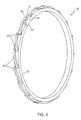
- FIGs. 2-4, 5 and 6 illustrate exemplary embodiments of a non-sealing, self-lubricating ring having such slanted surfaces in accordance with the present invention.
- a non-sealing, self-lubricating ring 20 includes an annular body 21, and a plurality of radial fins 22 formed on the outer surface of annular body 21.
- fins 22 obliquely extend between upper and lower end faces 31, 32 of annular body 21. More particularly, fins 22 extend from upper end face 31 of annular body 21 to the lower end face 32 thereof.
- Each adjacent pair of fins 22 forms in between a channel 23 which also obliquely extends between upper and lower end faces 31, 32 of annular body 21.
- Non-sealing self-lubricating ring 50 comprises an annular body 51 and radial fins 52 formed on the outer surface of annular body 51.
- Ring 50 differs from ring 20 in that ring 50 has channels 53 smaller than fins 52 while in ring 20, channels 23 are larger than fins 22.
- fins 52 of ring 50 are slanted at a steeper angle than that of fins 22 in ring 20.
- both rings 20 and 50 are formed with a plurality of gas/fluid passages (in the form of channels 23, 53) which communicate upper and lower end faces of the rings. Therefore, during engine operation, i.e.
- channels 23, 53 have been shown and described to be formed at the interface of cylinder wall 11 and non-sealing, self-lubricating ring 20, 50, other arrangements can be contemplated.
- the gas/fluid passages can be formed inside the non-sealing, self-lubricating ring itself (not shown).
- the non-sealing, self-lubricating ring of the present invention does not necessarily have the "open" configurations with gas/fluid passages as depicted in Figs. 2-3 and 5. A "closed" configuration may be available as illustrated in Fig. 6.
- non-sealing, self-lubricating ring 60 has an inner annular body 61 and a plurality of slanted primary fins 62.
- Ring 60 further includes a plurality of secondary fins 63 extending between the end faces of annular body 61 and connecting adjacent primary fins 62 with each other.
- secondary fins 63 extend substantially in the axial direction of the cylinder and therefore will not impede rotation of ring 60.
- the slanted upper and under sides of primary fins 62 will be acted upon by gasses and fluids contained in the cylinder thereby causing ring 60 to rotate.
- non-sealing, self-lubricating ring 15 loosely fits in an annular groove 16 formed in a wall of piston 12.
- An inner portion of ring 15, such as annular body 21 or 51 of rings 20, 50, is at least partially received within groove 16.
- the non-sealing, loose fit between cylinder wall 11 and ring 15 allows ring 15 to rotate and distribute its lubricity evenly on cylinder wall 11.
- ring 15 needs to be in constant contact with cylinder wall 11.
- an O-ring or other type ring 70 is preferably placed behind, or partially embedded in, non-sealing, self-lubricating ring 15 to maintain a certain contact force to cylinder wall 11, so that the transfer of the wearable low-friction material is maintained.
- the contact force exercised by O-ring 70 and non-sealing, self-lubricating ring 15 on cylinder wall 11 is not necessarily as large as a sealing force required to seal between e.g. piston rings 13, 14 and cylinder wall 11. Instead, the contact force should be sufficiently small to not impede rotation of ring 15.
- ring 15 can be molded directly over a spring steel ring or a wire spring ring (not shown) by, e.g., an insert molding process. In this manner, ring 15 can have more controlled and longer lasting spring properties.
- the gas/fluid passages of the non-sealing, self-lubricating ring such as channels 23, 53 of rings 20, 50, completely in gap 18 between cylinder wall 11 and piston 12, as shown in Fig. 1. Then, the gas/fluid passages will not be limited, at least partially, by the piston wall immediately above and below groove 16.
- ring 20 may be discontinuous and have a split 23 which is shown in larger detail in Fig. 4.
- ring 20 has first and second circumferential end portions 41, 42 overlapping each other.
- ring 60 has first and second circumferential end portions 64, 65 overlapping each other.
- the difference between ring 20 and 60 resides in that circumferential end portions 64, 65 of ring 60 further include projections 66, 67, respectively, extending toward one another.
- a step lock is formed to keep ring 60 in place after ring 60 has been installed on piston 12.
- FIG. 5 Another split annulus arrangement for the non-sealing, self-lubricating ring of the present invention is depicted in Fig. 5 at 54.
- ring 50 extends circumferentially for less than 360 degree, and has a first end 55 stopping short of a second end 56. Spacing 54 between first and second ends 55, 56 is approximately of the same size as channels 53 formed between fins 52.
- the sealing rings are not required to be made of a material with high self-lubricating properties, and can be configured to provide sufficient friction with the cylinder wall to retain the piston at the top of the stroke.
- the non-sealing, self-lubricating ring is not required to function as a seal between the piston and the cylinder. Therefore, the non-sealing, self-lubricating ring may have many different shapes and geometries to achieve optimal lubrication of the cylinder wall. The non-sealing, self-lubricating ring may be even configured to rotate about the piston during engine operation to uniformly transfer the self-lubricating material on the cylinder wall. The service life of the non-sealing, self-lubricating ring is thus prolonged.
- a self-lubricating ring is configured to also form a complete seal between the piston and the cylinder because such a self-lubricating sealing ring would not be able to rotate and evenly distribute its lubricity to the cylinder wall.
- the service life of the self-lubricating sealing ring is also shortened.
Landscapes
- Engineering & Computer Science (AREA)
- Chemical & Material Sciences (AREA)
- Combustion & Propulsion (AREA)
- Mechanical Engineering (AREA)
- General Engineering & Computer Science (AREA)
- Pistons, Piston Rings, And Cylinders (AREA)
- Portable Nailing Machines And Staplers (AREA)
Abstract
Description
Claims (25)
- A non-sealing, self-lubricating piston ring, comprising
an annular cylindrical body adapted to be mounted on and carried by a piston (12) axially movable within a cylinder (11) said body being defined by first and second end faces axially spaced by a thickness of said body and by inner and outer circumferential surfaces ; and
a plurality of fins (22, 52, 62) of a low-friction wearable material formed on the outer circumferential surface of said body and adapted to be in constant contact with an inner wall of the cylinder, said fins extending obliquely between the first and second end faces of said body to promote rotation of said non-sealing, self-lubricating ring about the piston during axial movements of the piston within the cylinder thereby uniformly transferring said low-friction wearable material onto the inner wall of the cylinder. - The non-sealing, self-lubricating ring of claim 1, wherein said low-friction wearable material is PTFE.
- The non-sealing, self-lubricating ring of claim 1 or 2, wherein said fins extend from the first end face to the second end face of said body.
- The non-sealing, self-lubricating ring according any of claims 1 to 3, wherein said fins form a plurality of channels (23, 53) therebetween, whereby gases contained in the cylinder are free to move from the first end face to the second end face of said body.
- The non-sealing, self-lubricating ring of claim 4, wherein said fins (52) have a circumferential dimension larger than that of said channels (53).
- The non-sealing, self-lubricating ring according any of claims 1 to 5, wherein said fins are distributed evenly circumferentially of said body.
- The non-sealing, self-lubricating ring according any of claims 1 to 6, wherein said body (21,51,61) is formed as a split annulus.
- The non-sealing, self-lubricating ring of claim 7, wherein said body extends circumferentially for less than 360 degrees, and has first (55) and second (56) ends circumferentially spaced from each other.
- The non-sealing, self-lubricating ring of claim 8, wherein a spacing (54) between the first and second ends of said body is located between adjacent ones of said fins.
- The non-sealing, self-lubricating ring of claim 7, wherein said body extends circumferentially for more than 360 degrees, and has first (41) and second (42) end portions overlapping each other.
- The non-sealing, self-lubricating ring of claim 10, wherein the first and second end portions extend from the first and second end faces toward the second and first end faces of said body, respectively, to cooperatively form a step lock.
- The non-sealing, self-lubricating ring of claim 1, further comprising a plurality of secondary (63) fins on the outer circumferential surface of said body, each of said secondary fins extending between the first and second end faces of said body and connecting an adjacent pair of said fins.
- The non-sealing, self-lubricating ring of claim 12, wherein said secondary fins extend substantially axially of the cylinder.
- The non-sealing, self-lubricating ring according any of claims 1 to 13, further comprising an O-ring (70) at least partially embedded in said body in the inner circumferential surface side of said body.
- The non-sealing, self-lubricating ring of claim 1, wherein said body and said fins are integrally molded as a single piece directly over a wire spring ring.
- A piston assembly, comprising:a reciprocating piston (12) axially movable within a cylinder (11),at least one sealing ring (13, 14) for sealing between an inner wall of the cylinder and the piston ; anda non-sealing, self-lubricating ring (15) positioned between the inner wall of the cylinder and the piston and axially spaced from said at least one sealing ring, said non-sealing, self-lubricating ring made at least partially of a low-friction wearable material.
- The piston assembly of claim 16, wherein said at least one sealing ring is made of steel.
- The piston assembly of claim 16, wherein the non-sealing, self-lubricating ring comprises
an inner circumferential portion at least partially received in an annular groove formed on the piston ; and
an outer circumferential portion made of said low-friction wearable material and adapted to be in constant contact with the inner wall of the cylinder. - The piston assembly of claim 16, with a non-sealing, self-lubricating ring according any of the claims 1 to 15.
- A internal combustion engine for a fastener driving tool, comprising
a piston assembly according any of the claims 16 to 19. - The internal combustion engine of claim 20, wherein the non-sealing, self-lubricating ring is loosely mounted on the piston.
- The internal combustion engine of claim 20, wherein said at least one sealing ring is positioned between the combustion chamber and said non-sealing, self-lubricating ring.
- The internal combustion engine of claim 20, wherein said non-sealing, self-lubricating ring is configured to rotate about the piston during axial movements of the piston within the cylinder, thereby uniformly transferring said low-friction wearable material onto the cylinder wall.
- The internal combustion engine of claim 20, wherein said at least one sealing ring is configured to provide necessary fiction between the cylinder wall and the piston to retain the piston at a top-of the-stroke position during operation of the internal combustion engine.
- The internal combustion engine of claim 20, wherein the combustion chamber is filed with lubricant-free fuel during operation of the internal combustion engine.
Applications Claiming Priority (2)
| Application Number | Priority Date | Filing Date | Title |
|---|---|---|---|
| US945443 | 2001-08-30 | ||
| US09/945,443 US6685193B2 (en) | 2001-08-30 | 2001-08-30 | Self lubricating, non-sealing piston ring for an internal combustion fastener driving tool |
Publications (3)
| Publication Number | Publication Date |
|---|---|
| EP1293302A2 true EP1293302A2 (en) | 2003-03-19 |
| EP1293302A3 EP1293302A3 (en) | 2004-05-12 |
| EP1293302B1 EP1293302B1 (en) | 2007-08-01 |
Family
ID=25483092
Family Applications (1)
| Application Number | Title | Priority Date | Filing Date |
|---|---|---|---|
| EP02292118A Expired - Lifetime EP1293302B1 (en) | 2001-08-30 | 2002-08-28 | A self lubricating, non-sealing piston ring for an internal combustion fastener driving tool |
Country Status (12)
| Country | Link |
|---|---|
| US (1) | US6685193B2 (en) |
| EP (1) | EP1293302B1 (en) |
| JP (1) | JP4290944B2 (en) |
| KR (1) | KR20030019844A (en) |
| CN (1) | CN1256506C (en) |
| AT (1) | ATE368813T1 (en) |
| AU (1) | AU2002300712B2 (en) |
| DE (1) | DE60221475T2 (en) |
| DK (1) | DK1293302T3 (en) |
| ES (1) | ES2289065T3 (en) |
| MX (1) | MXPA02008405A (en) |
| TW (1) | TW536598B (en) |
Cited By (4)
| Publication number | Priority date | Publication date | Assignee | Title |
|---|---|---|---|---|
| WO2005123347A1 (en) * | 2004-06-14 | 2005-12-29 | Illinois Tool Works Inc. | Seal for portable fastener driving tool |
| EP3006788A4 (en) * | 2013-06-03 | 2017-02-15 | NOK Corporation | Seal ring |
| EP3199301A1 (en) * | 2016-02-01 | 2017-08-02 | HILTI Aktiengesellschaft | Combustion chamber and driving tool |
| EP3237150A4 (en) * | 2014-12-23 | 2017-12-27 | Techtronic Industries Company Limited | Drive blade lubrication assembly and powered fastener driver containing the same |
Families Citing this family (24)
| Publication number | Priority date | Publication date | Assignee | Title |
|---|---|---|---|---|
| JP4079170B2 (en) * | 2002-07-26 | 2008-04-23 | Nok株式会社 | Seal ring |
| KR100624734B1 (en) * | 2005-05-11 | 2006-09-15 | 엘지전자 주식회사 | Lubricating oil pump of linear compressor |
| JP5287715B2 (en) | 2007-04-09 | 2013-09-11 | Nok株式会社 | Sealing device |
| US20080272326A1 (en) * | 2007-05-02 | 2008-11-06 | Buck William C | Driving tool and head valve assembly for a driving tool |
| US8555635B2 (en) * | 2009-01-15 | 2013-10-15 | Hallite Seals Americas, Inc. | Hydraulic system for synchronizing a plurality of pistons and an associated method |
| SE533233C2 (en) * | 2009-01-26 | 2010-07-27 | Heed Consulting Ab | sealing sleeve |
| CN101813034A (en) * | 2010-04-01 | 2010-08-25 | 奇瑞汽车股份有限公司 | Piston ring for optical controlled engine |
| JP5620794B2 (en) * | 2010-11-18 | 2014-11-05 | いすゞ自動車株式会社 | piston ring |
| US20180274675A1 (en) * | 2012-11-09 | 2018-09-27 | Federal-Mogul Burscheid Gmbh | Piston ring with varying apex lines |
| DE102013206399A1 (en) * | 2013-04-11 | 2014-10-16 | Federal-Mogul Friedberg Gmbh | Piston ring with periodically varying tread width |
| KR102122837B1 (en) * | 2014-02-21 | 2020-06-15 | 두산인프라코어 주식회사 | Piston ring and piston having the same |
| EP2954983B1 (en) * | 2014-06-10 | 2017-03-08 | Sandvik Mining and Construction Oy | Seal of tool and method of sealing |
| US10759031B2 (en) | 2014-08-28 | 2020-09-01 | Power Tech Staple and Nail, Inc. | Support for elastomeric disc valve in combustion driven fastener hand tool |
| US9862083B2 (en) | 2014-08-28 | 2018-01-09 | Power Tech Staple and Nail, Inc. | Vacuum piston retention for a combustion driven fastener hand tool |
| KR101637705B1 (en) * | 2014-10-28 | 2016-07-07 | 현대자동차주식회사 | Piston Assembly for Vehicle Engine |
| US10344862B2 (en) | 2015-01-12 | 2019-07-09 | Rolls-Royce Corporation | Shaft coupling seal assembly |
| DE102015109826A1 (en) * | 2015-06-19 | 2016-12-22 | Federal-Mogul Burscheid Gmbh | Piston ring with groove seal |
| EP3184250A1 (en) * | 2015-12-22 | 2017-06-28 | HILTI Aktiengesellschaft | Internal combustion gas operated driving tool |
| EP3565913B1 (en) * | 2017-01-06 | 2023-05-03 | Materion Corporation | Piston compression rings of copper-nickel-tin alloys |
| USD838752S1 (en) * | 2017-04-28 | 2019-01-22 | Lindsay Corporation | Track belt for irrigation systems |
| USD890310S1 (en) * | 2018-02-08 | 2020-07-14 | Nok Corporation | Seal |
| US11624314B2 (en) | 2018-08-21 | 2023-04-11 | Power Tech Staple and Nail, Inc. | Combustion chamber valve and fuel system for driven fastener hand tool |
| EP3867017B1 (en) * | 2018-10-17 | 2025-04-09 | Kyocera Senco Industrial Tools, Inc. | Working cylinder for power tool with piston lubricating system |
| DE102020100652B4 (en) | 2020-01-14 | 2022-03-17 | Helga Wanzke | Sealing arrangement with an insertable ring seal for external, internal or flange sealing |
Family Cites Families (47)
| Publication number | Priority date | Publication date | Assignee | Title |
|---|---|---|---|---|
| US307334A (en) * | 1884-10-28 | Anti-friction packing for pistons | ||
| US1406763A (en) * | 1920-12-11 | 1922-02-14 | John L Schoen | Piston ring |
| US1457461A (en) * | 1921-10-03 | 1923-06-05 | Renshaw Joseph Howard | Metallic packing |
| US1806143A (en) * | 1923-03-14 | 1931-05-19 | Simplex Piston Ring Company | Piston ring |
| US1877414A (en) * | 1925-02-13 | 1932-09-13 | Simplex Piston Ring Company | Piston packing |
| US1710485A (en) * | 1927-02-09 | 1929-04-23 | Leo J Mckone | Piston ring |
| US1769974A (en) * | 1927-08-03 | 1930-07-08 | Otto E Szekely | Piston ring |
| US2258169A (en) * | 1939-03-10 | 1941-10-07 | Standard Piston Ring Company | Lamina for assembled piston rings |
| US2345589A (en) * | 1940-10-21 | 1944-04-04 | Wilkening Mfg Co | Piston ring |
| US2428031A (en) * | 1944-03-31 | 1947-09-30 | Mayes Martin | Piston and sealing ring therefor |
| FR1599308A (en) * | 1968-06-08 | 1970-07-15 | ||
| DE1918690C3 (en) * | 1969-04-12 | 1974-08-08 | Demag Ag, 4100 Duisburg | Sealing ring |
| DE1929630A1 (en) | 1969-06-11 | 1971-01-07 | Linde Ag | Dry running piston machine, for example dry running piston compressor, the pistons of which are equipped with so-called captured piston rings |
| US3784215A (en) * | 1971-11-12 | 1974-01-08 | Koppers Co Inc | Interlocking joint for sealing rings |
| US4094519A (en) * | 1972-02-14 | 1978-06-13 | Chicago Rawhide Manufacturing Company | Shaft seal with helical pumping element |
| US3735992A (en) * | 1972-03-14 | 1973-05-29 | I S Prostorov | Piston ring |
| DE2239488A1 (en) * | 1972-08-11 | 1974-02-21 | Bauer Kompressoren | PISTON MACHINE, IN PARTICULAR DRY RUNNING PISTON COMPRESSORS, WITH GUIDE RING |
| PL76739B1 (en) | 1973-05-10 | 1975-02-28 | ||
| AR205075A1 (en) * | 1975-01-01 | 1976-03-31 | Leone M | LUBRICATION RETAINER |
| US4102608A (en) * | 1975-12-24 | 1978-07-25 | Commonwealth Scientific And Industrial Research Organization | Reciprocatory piston and cylinder machines |
| US5312117A (en) * | 1977-04-12 | 1994-05-17 | Taiho Kogyo Co., Ltd. | Mechanical seal |
| US4200213A (en) * | 1977-08-10 | 1980-04-29 | Agence Nationale De Valorisation De La Recherche (Anvar) | Percussion apparatus |
| US4516481A (en) * | 1981-02-06 | 1985-05-14 | Robert Geffroy | Piston and piston rings set |
| US4533149A (en) * | 1981-06-10 | 1985-08-06 | J. I. Case Company | Split seal ring with interlocking cut |
| GB8321051D0 (en) * | 1983-08-04 | 1983-09-07 | Ae Plc | Piston rings |
| US4526388A (en) | 1984-05-17 | 1985-07-02 | Dixon Industries Corporation | One-piece sealing ring for a shaft |
| US4610319A (en) * | 1984-10-15 | 1986-09-09 | Kalsi Manmohan S | Hydrodynamic lubricant seal for drill bits |
| US4576381A (en) | 1984-11-23 | 1986-03-18 | Rix Industries | Spiral piston ring with tapered ends and recesses |
| DE3520668A1 (en) * | 1985-06-08 | 1986-06-26 | Daimler-Benz Ag, 7000 Stuttgart | Continuous piston ring |
| US5172921A (en) * | 1985-09-16 | 1992-12-22 | Flutron Ab | Sealing device |
| DE3621726A1 (en) | 1986-06-28 | 1988-01-14 | Deutsche Forsch Luft Raumfahrt | PISTON PUMP FOR CONVEYING A CRYOGENIC LIQUID |
| AU634731B2 (en) * | 1988-12-02 | 1993-03-04 | Sanden Corporation | Piston ring having a function which is for facilitating supply of lubricating oil into an annular groove of a piston |
| US5193821A (en) * | 1989-03-31 | 1993-03-16 | Leber Corporation | Substantially zero leakage path sealing assembly with zero degree bias angle |
| US5117742A (en) * | 1989-04-28 | 1992-06-02 | Iwata Air Compressor Mfg. Co. Ltd. | Piston of composite material with c-shaped ring groove |
| US5378123A (en) * | 1990-02-02 | 1995-01-03 | Carmelo J. Scuderi | Apparatus for recovering refrigerant with offset cam |
| US5191861A (en) * | 1991-07-12 | 1993-03-09 | Stanley-Bostitch, Inc. | Internal combustion actuated portable tool |
| US5409240A (en) | 1992-11-12 | 1995-04-25 | Unilab Bearing Protection Company, Inc. | Seal with self-lubricating contact surface |
| US5695199A (en) * | 1994-03-14 | 1997-12-09 | Rao; V. Durga Nageswar | Piston sealing assembly |
| US5524904A (en) * | 1994-11-10 | 1996-06-11 | Kelsey-Hayes Company | Lip seal for antilock braking system isolation valve and similar valves |
| US5794516A (en) | 1995-08-30 | 1998-08-18 | Ingersoll-Rand Company | Piston for a self-lubricating, fluid-actuated, percussive down-the-hole drill |
| CN2233988Y (en) | 1995-09-27 | 1996-08-28 | 王保东 | Automatic lubricating and gap-adjusting piston ring |
| DE19630745A1 (en) * | 1996-07-30 | 1998-02-05 | Hans Helpap | Sealing package |
| US5676380A (en) * | 1996-10-02 | 1997-10-14 | Ingersoll-Rand Company | Venting piston ring |
| US6158643A (en) | 1997-12-31 | 2000-12-12 | Porter-Cable Corporation | Internal combustion fastener driving tool piston and piston ring |
| US6494462B2 (en) * | 1998-05-06 | 2002-12-17 | Kalsi Engineering, Inc. | Rotary seal with improved dynamic interface |
| US6116489A (en) * | 1998-10-28 | 2000-09-12 | Pow-R-Tools Corporation | Manually operable internal combustion-type impact tool with reduced recycler stroke |
| US6142393A (en) * | 1999-11-22 | 2000-11-07 | Lincoln Industrial Corporation | Cap seal for lubricant injector |
-
2001
- 2001-08-30 US US09/945,443 patent/US6685193B2/en not_active Expired - Fee Related
-
2002
- 2002-06-26 KR KR1020020035975A patent/KR20030019844A/en not_active Ceased
- 2002-08-16 CN CNB021305560A patent/CN1256506C/en not_active Expired - Fee Related
- 2002-08-21 AU AU2002300712A patent/AU2002300712B2/en not_active Ceased
- 2002-08-23 TW TW091119100A patent/TW536598B/en not_active IP Right Cessation
- 2002-08-26 JP JP2002244914A patent/JP4290944B2/en not_active Expired - Fee Related
- 2002-08-28 DK DK02292118T patent/DK1293302T3/en active
- 2002-08-28 ES ES02292118T patent/ES2289065T3/en not_active Expired - Lifetime
- 2002-08-28 DE DE60221475T patent/DE60221475T2/en not_active Expired - Lifetime
- 2002-08-28 AT AT02292118T patent/ATE368813T1/en not_active IP Right Cessation
- 2002-08-28 MX MXPA02008405A patent/MXPA02008405A/en active IP Right Grant
- 2002-08-28 EP EP02292118A patent/EP1293302B1/en not_active Expired - Lifetime
Cited By (7)
| Publication number | Priority date | Publication date | Assignee | Title |
|---|---|---|---|---|
| WO2005123347A1 (en) * | 2004-06-14 | 2005-12-29 | Illinois Tool Works Inc. | Seal for portable fastener driving tool |
| EP3006788A4 (en) * | 2013-06-03 | 2017-02-15 | NOK Corporation | Seal ring |
| US10634254B2 (en) | 2013-06-03 | 2020-04-28 | Nok Corporation | Seal ring |
| EP3237150A4 (en) * | 2014-12-23 | 2017-12-27 | Techtronic Industries Company Limited | Drive blade lubrication assembly and powered fastener driver containing the same |
| US10518396B2 (en) | 2014-12-23 | 2019-12-31 | Tti (Macao Commercial Offshore) Limited | Drive blade lubrication assembly and powered fastener driver containing the same |
| EP3199301A1 (en) * | 2016-02-01 | 2017-08-02 | HILTI Aktiengesellschaft | Combustion chamber and driving tool |
| WO2017134021A1 (en) * | 2016-02-01 | 2017-08-10 | Hilti Aktiengesellschaft | Combustion chamber and drive-in device |
Also Published As
| Publication number | Publication date |
|---|---|
| DK1293302T3 (en) | 2007-10-29 |
| DE60221475D1 (en) | 2007-09-13 |
| EP1293302B1 (en) | 2007-08-01 |
| TW536598B (en) | 2003-06-11 |
| US6685193B2 (en) | 2004-02-03 |
| ES2289065T3 (en) | 2008-02-01 |
| KR20030019844A (en) | 2003-03-07 |
| US20030042686A1 (en) | 2003-03-06 |
| JP4290944B2 (en) | 2009-07-08 |
| MXPA02008405A (en) | 2003-03-05 |
| EP1293302A3 (en) | 2004-05-12 |
| CN1407224A (en) | 2003-04-02 |
| ATE368813T1 (en) | 2007-08-15 |
| AU2002300712B2 (en) | 2004-12-23 |
| DE60221475T2 (en) | 2008-05-15 |
| CN1256506C (en) | 2006-05-17 |
| JP2003097711A (en) | 2003-04-03 |
Similar Documents
| Publication | Publication Date | Title |
|---|---|---|
| EP1293302B1 (en) | A self lubricating, non-sealing piston ring for an internal combustion fastener driving tool | |
| CA2836807C (en) | Eccentricity tolerant valve stem seal assembly | |
| US6378872B1 (en) | Seal assembly | |
| EP1184558B1 (en) | Piston and piston ring assembly | |
| US4384729A (en) | Interlocking dual plane gapped compression rings | |
| US6615788B2 (en) | Piston assembly for an internal combustion engine | |
| US4210338A (en) | Piston ring assembly | |
| US5072653A (en) | Piston biased to one side to cover ring gap | |
| CN104220791A (en) | Piston ring for an internal combustion engine | |
| JP6240098B2 (en) | Piston rings for internal combustion engines | |
| US7429047B1 (en) | Piston ring assembly | |
| US5197746A (en) | Substantially zero leakage path sealing assembly with expander void | |
| JP3890750B2 (en) | Valve stem seal | |
| US6135008A (en) | Piston with lubricant-scraping ring and lubricant return ports | |
| US5147094A (en) | Substantially zero leakage path sealing assembly with insulating member | |
| CN104246190B (en) | Piston rings for internal combustion engines | |
| JP3799629B2 (en) | Piston ring structure | |
| JPH08226542A (en) | piston ring | |
| CN119572458B (en) | A combined sealing piston structure for a liquid-driven piston compressor | |
| JP6345124B2 (en) | Piston rings for internal combustion engines | |
| WO1998016763A1 (en) | Gap-sealed piston ring | |
| KR20210108698A (en) | Oil seal | |
| EP1599666A1 (en) | Piston assembly for an internal combustion engine | |
| KR19980026904A (en) | Valve structure of automobile engine | |
| JP2007532813A (en) | Piston rod sealing ring |
Legal Events
| Date | Code | Title | Description |
|---|---|---|---|
| PUAI | Public reference made under article 153(3) epc to a published international application that has entered the european phase |
Free format text: ORIGINAL CODE: 0009012 |
|
| AK | Designated contracting states |
Kind code of ref document: A2 Designated state(s): AT BE BG CH CY CZ DE DK EE ES FI FR GB GR IE IT LI LU MC NL PT SE SK TR Designated state(s): AT BE BG CH CY CZ DE DK EE ES FI FR GB GR IE IT LI LU MC NL PT SE SK TR |
|
| AX | Request for extension of the european patent |
Extension state: AL LT LV MK RO SI |
|
| PUAL | Search report despatched |
Free format text: ORIGINAL CODE: 0009013 |
|
| RIC1 | Information provided on ipc code assigned before grant |
Ipc: 7F 16J 9/20 B Ipc: 7F 16J 9/28 B Ipc: 7B 25C 1/08 B Ipc: 7F 16J 9/00 A |
|
| AK | Designated contracting states |
Kind code of ref document: A3 Designated state(s): AT BE BG CH CY CZ DE DK EE ES FI FR GB GR IE IT LI LU MC NL PT SE SK TR |
|
| AX | Request for extension of the european patent |
Extension state: AL LT LV MK RO SI |
|
| 17P | Request for examination filed |
Effective date: 20041112 |
|
| AKX | Designation fees paid |
Designated state(s): AT BE BG CH CY CZ DE DK EE ES FI FR GB GR IE IT LI LU MC NL PT SE SK TR |
|
| 17Q | First examination report despatched |
Effective date: 20060719 |
|
| GRAP | Despatch of communication of intention to grant a patent |
Free format text: ORIGINAL CODE: EPIDOSNIGR1 |
|
| GRAS | Grant fee paid |
Free format text: ORIGINAL CODE: EPIDOSNIGR3 |
|
| GRAA | (expected) grant |
Free format text: ORIGINAL CODE: 0009210 |
|
| AK | Designated contracting states |
Kind code of ref document: B1 Designated state(s): AT BE BG CH CY CZ DE DK EE ES FI FR GB GR IE IT LI LU MC NL PT SE SK TR |
|
| REG | Reference to a national code |
Ref country code: GB Ref legal event code: FG4D |
|
| REG | Reference to a national code |
Ref country code: CH Ref legal event code: EP |
|
| REG | Reference to a national code |
Ref country code: IE Ref legal event code: FG4D |
|
| REF | Corresponds to: |
Ref document number: 60221475 Country of ref document: DE Date of ref document: 20070913 Kind code of ref document: P |
|
| REG | Reference to a national code |
Ref country code: DK Ref legal event code: T3 |
|
| ET | Fr: translation filed | ||
| PG25 | Lapsed in a contracting state [announced via postgrant information from national office to epo] |
Ref country code: FI Free format text: LAPSE BECAUSE OF FAILURE TO SUBMIT A TRANSLATION OF THE DESCRIPTION OR TO PAY THE FEE WITHIN THE PRESCRIBED TIME-LIMIT Effective date: 20070801 Ref country code: BG Free format text: LAPSE BECAUSE OF FAILURE TO SUBMIT A TRANSLATION OF THE DESCRIPTION OR TO PAY THE FEE WITHIN THE PRESCRIBED TIME-LIMIT Effective date: 20071101 |
|
| REG | Reference to a national code |
Ref country code: ES Ref legal event code: FG2A Ref document number: 2289065 Country of ref document: ES Kind code of ref document: T3 |
|
| REG | Reference to a national code |
Ref country code: CH Ref legal event code: PL |
|
| PG25 | Lapsed in a contracting state [announced via postgrant information from national office to epo] |
Ref country code: CH Free format text: LAPSE BECAUSE OF FAILURE TO SUBMIT A TRANSLATION OF THE DESCRIPTION OR TO PAY THE FEE WITHIN THE PRESCRIBED TIME-LIMIT Effective date: 20070801 Ref country code: LI Free format text: LAPSE BECAUSE OF FAILURE TO SUBMIT A TRANSLATION OF THE DESCRIPTION OR TO PAY THE FEE WITHIN THE PRESCRIBED TIME-LIMIT Effective date: 20070801 |
|
| PG25 | Lapsed in a contracting state [announced via postgrant information from national office to epo] |
Ref country code: MC Free format text: LAPSE BECAUSE OF NON-PAYMENT OF DUE FEES Effective date: 20070831 Ref country code: GR Free format text: LAPSE BECAUSE OF FAILURE TO SUBMIT A TRANSLATION OF THE DESCRIPTION OR TO PAY THE FEE WITHIN THE PRESCRIBED TIME-LIMIT Effective date: 20071102 |
|
| PG25 | Lapsed in a contracting state [announced via postgrant information from national office to epo] |
Ref country code: SK Free format text: LAPSE BECAUSE OF FAILURE TO SUBMIT A TRANSLATION OF THE DESCRIPTION OR TO PAY THE FEE WITHIN THE PRESCRIBED TIME-LIMIT Effective date: 20070801 Ref country code: PT Free format text: LAPSE BECAUSE OF FAILURE TO SUBMIT A TRANSLATION OF THE DESCRIPTION OR TO PAY THE FEE WITHIN THE PRESCRIBED TIME-LIMIT Effective date: 20080102 Ref country code: CZ Free format text: LAPSE BECAUSE OF FAILURE TO SUBMIT A TRANSLATION OF THE DESCRIPTION OR TO PAY THE FEE WITHIN THE PRESCRIBED TIME-LIMIT Effective date: 20070801 |
|
| PLBE | No opposition filed within time limit |
Free format text: ORIGINAL CODE: 0009261 |
|
| STAA | Information on the status of an ep patent application or granted ep patent |
Free format text: STATUS: NO OPPOSITION FILED WITHIN TIME LIMIT |
|
| PG25 | Lapsed in a contracting state [announced via postgrant information from national office to epo] |
Ref country code: SE Free format text: LAPSE BECAUSE OF FAILURE TO SUBMIT A TRANSLATION OF THE DESCRIPTION OR TO PAY THE FEE WITHIN THE PRESCRIBED TIME-LIMIT Effective date: 20071101 |
|
| 26N | No opposition filed |
Effective date: 20080506 |
|
| PG25 | Lapsed in a contracting state [announced via postgrant information from national office to epo] |
Ref country code: EE Free format text: LAPSE BECAUSE OF FAILURE TO SUBMIT A TRANSLATION OF THE DESCRIPTION OR TO PAY THE FEE WITHIN THE PRESCRIBED TIME-LIMIT Effective date: 20070801 |
|
| PG25 | Lapsed in a contracting state [announced via postgrant information from national office to epo] |
Ref country code: CY Free format text: LAPSE BECAUSE OF FAILURE TO SUBMIT A TRANSLATION OF THE DESCRIPTION OR TO PAY THE FEE WITHIN THE PRESCRIBED TIME-LIMIT Effective date: 20070801 |
|
| PG25 | Lapsed in a contracting state [announced via postgrant information from national office to epo] |
Ref country code: LU Free format text: LAPSE BECAUSE OF NON-PAYMENT OF DUE FEES Effective date: 20070828 |
|
| PG25 | Lapsed in a contracting state [announced via postgrant information from national office to epo] |
Ref country code: TR Free format text: LAPSE BECAUSE OF FAILURE TO SUBMIT A TRANSLATION OF THE DESCRIPTION OR TO PAY THE FEE WITHIN THE PRESCRIBED TIME-LIMIT Effective date: 20070801 |
|
| PGFP | Annual fee paid to national office [announced via postgrant information from national office to epo] |
Ref country code: IE Payment date: 20090825 Year of fee payment: 8 Ref country code: ES Payment date: 20090826 Year of fee payment: 8 Ref country code: DK Payment date: 20090827 Year of fee payment: 8 |
|
| PGFP | Annual fee paid to national office [announced via postgrant information from national office to epo] |
Ref country code: NL Payment date: 20090824 Year of fee payment: 8 Ref country code: AT Payment date: 20090803 Year of fee payment: 8 |
|
| PGFP | Annual fee paid to national office [announced via postgrant information from national office to epo] |
Ref country code: BE Payment date: 20090915 Year of fee payment: 8 |
|
| PGFP | Annual fee paid to national office [announced via postgrant information from national office to epo] |
Ref country code: IT Payment date: 20090825 Year of fee payment: 8 |
|
| BERE | Be: lapsed |
Owner name: ILLINOIS TOOL WORKS INC. Effective date: 20100831 |
|
| REG | Reference to a national code |
Ref country code: NL Ref legal event code: V1 Effective date: 20110301 |
|
| REG | Reference to a national code |
Ref country code: DK Ref legal event code: EBP |
|
| PG25 | Lapsed in a contracting state [announced via postgrant information from national office to epo] |
Ref country code: AT Free format text: LAPSE BECAUSE OF NON-PAYMENT OF DUE FEES Effective date: 20100828 Ref country code: IT Free format text: LAPSE BECAUSE OF NON-PAYMENT OF DUE FEES Effective date: 20100828 Ref country code: NL Free format text: LAPSE BECAUSE OF NON-PAYMENT OF DUE FEES Effective date: 20110301 |
|
| PG25 | Lapsed in a contracting state [announced via postgrant information from national office to epo] |
Ref country code: BE Free format text: LAPSE BECAUSE OF NON-PAYMENT OF DUE FEES Effective date: 20100831 Ref country code: IE Free format text: LAPSE BECAUSE OF NON-PAYMENT OF DUE FEES Effective date: 20100830 |
|
| PG25 | Lapsed in a contracting state [announced via postgrant information from national office to epo] |
Ref country code: DK Free format text: LAPSE BECAUSE OF NON-PAYMENT OF DUE FEES Effective date: 20100831 |
|
| REG | Reference to a national code |
Ref country code: ES Ref legal event code: FD2A Effective date: 20111019 |
|
| PG25 | Lapsed in a contracting state [announced via postgrant information from national office to epo] |
Ref country code: ES Free format text: LAPSE BECAUSE OF NON-PAYMENT OF DUE FEES Effective date: 20100829 |
|
| PGFP | Annual fee paid to national office [announced via postgrant information from national office to epo] |
Ref country code: DE Payment date: 20140827 Year of fee payment: 13 |
|
| PGFP | Annual fee paid to national office [announced via postgrant information from national office to epo] |
Ref country code: FR Payment date: 20140818 Year of fee payment: 13 Ref country code: GB Payment date: 20140827 Year of fee payment: 13 |
|
| REG | Reference to a national code |
Ref country code: DE Ref legal event code: R119 Ref document number: 60221475 Country of ref document: DE |
|
| GBPC | Gb: european patent ceased through non-payment of renewal fee |
Effective date: 20150828 |
|
| REG | Reference to a national code |
Ref country code: FR Ref legal event code: ST Effective date: 20160429 |
|
| PG25 | Lapsed in a contracting state [announced via postgrant information from national office to epo] |
Ref country code: DE Free format text: LAPSE BECAUSE OF NON-PAYMENT OF DUE FEES Effective date: 20160301 Ref country code: GB Free format text: LAPSE BECAUSE OF NON-PAYMENT OF DUE FEES Effective date: 20150828 |
|
| PG25 | Lapsed in a contracting state [announced via postgrant information from national office to epo] |
Ref country code: FR Free format text: LAPSE BECAUSE OF NON-PAYMENT OF DUE FEES Effective date: 20150831 |