EP1293265B1 - Improved method and apparatus for repairing screens - Google Patents
Improved method and apparatus for repairing screens Download PDFInfo
- Publication number
- EP1293265B1 EP1293265B1 EP20020254479 EP02254479A EP1293265B1 EP 1293265 B1 EP1293265 B1 EP 1293265B1 EP 20020254479 EP20020254479 EP 20020254479 EP 02254479 A EP02254479 A EP 02254479A EP 1293265 B1 EP1293265 B1 EP 1293265B1
- Authority
- EP
- European Patent Office
- Prior art keywords
- mesh
- window
- damaged
- place
- windows
- Prior art date
- Legal status (The legal status is an assumption and is not a legal conclusion. Google has not performed a legal analysis and makes no representation as to the accuracy of the status listed.)
- Expired - Lifetime
Links
Images


Classifications
-
- B—PERFORMING OPERATIONS; TRANSPORTING
- B07—SEPARATING SOLIDS FROM SOLIDS; SORTING
- B07B—SEPARATING SOLIDS FROM SOLIDS BY SIEVING, SCREENING, SIFTING OR BY USING GAS CURRENTS; SEPARATING BY OTHER DRY METHODS APPLICABLE TO BULK MATERIAL, e.g. LOOSE ARTICLES FIT TO BE HANDLED LIKE BULK MATERIAL
- B07B1/00—Sieving, screening, sifting, or sorting solid materials using networks, gratings, grids, or the like
- B07B1/46—Constructional details of screens in general; Cleaning or heating of screens
- B07B1/4609—Constructional details of screens in general; Cleaning or heating of screens constructional details of screening surfaces or meshes
- B07B1/4627—Repairing of screening surfaces
-
- Y—GENERAL TAGGING OF NEW TECHNOLOGICAL DEVELOPMENTS; GENERAL TAGGING OF CROSS-SECTIONAL TECHNOLOGIES SPANNING OVER SEVERAL SECTIONS OF THE IPC; TECHNICAL SUBJECTS COVERED BY FORMER USPC CROSS-REFERENCE ART COLLECTIONS [XRACs] AND DIGESTS
- Y10—TECHNICAL SUBJECTS COVERED BY FORMER USPC
- Y10T—TECHNICAL SUBJECTS COVERED BY FORMER US CLASSIFICATION
- Y10T29/00—Metal working
- Y10T29/49—Method of mechanical manufacture
- Y10T29/49616—Structural member making
- Y10T29/4962—Grille making
-
- Y—GENERAL TAGGING OF NEW TECHNOLOGICAL DEVELOPMENTS; GENERAL TAGGING OF CROSS-SECTIONAL TECHNOLOGIES SPANNING OVER SEVERAL SECTIONS OF THE IPC; TECHNICAL SUBJECTS COVERED BY FORMER USPC CROSS-REFERENCE ART COLLECTIONS [XRACs] AND DIGESTS
- Y10—TECHNICAL SUBJECTS COVERED BY FORMER USPC
- Y10T—TECHNICAL SUBJECTS COVERED BY FORMER US CLASSIFICATION
- Y10T428/00—Stock material or miscellaneous articles
- Y10T428/12—All metal or with adjacent metals
- Y10T428/12347—Plural layers discontinuously bonded [e.g., spot-weld, mechanical fastener, etc.]
-
- Y—GENERAL TAGGING OF NEW TECHNOLOGICAL DEVELOPMENTS; GENERAL TAGGING OF CROSS-SECTIONAL TECHNOLOGIES SPANNING OVER SEVERAL SECTIONS OF THE IPC; TECHNICAL SUBJECTS COVERED BY FORMER USPC CROSS-REFERENCE ART COLLECTIONS [XRACs] AND DIGESTS
- Y10—TECHNICAL SUBJECTS COVERED BY FORMER USPC
- Y10T—TECHNICAL SUBJECTS COVERED BY FORMER US CLASSIFICATION
- Y10T428/00—Stock material or miscellaneous articles
- Y10T428/12—All metal or with adjacent metals
- Y10T428/12361—All metal or with adjacent metals having aperture or cut
-
- Y—GENERAL TAGGING OF NEW TECHNOLOGICAL DEVELOPMENTS; GENERAL TAGGING OF CROSS-SECTIONAL TECHNOLOGIES SPANNING OVER SEVERAL SECTIONS OF THE IPC; TECHNICAL SUBJECTS COVERED BY FORMER USPC CROSS-REFERENCE ART COLLECTIONS [XRACs] AND DIGESTS
- Y10—TECHNICAL SUBJECTS COVERED BY FORMER USPC
- Y10T—TECHNICAL SUBJECTS COVERED BY FORMER US CLASSIFICATION
- Y10T428/00—Stock material or miscellaneous articles
- Y10T428/12—All metal or with adjacent metals
- Y10T428/12444—Embodying fibers interengaged or between layers [e.g., paper, etc.]
-
- Y—GENERAL TAGGING OF NEW TECHNOLOGICAL DEVELOPMENTS; GENERAL TAGGING OF CROSS-SECTIONAL TECHNOLOGIES SPANNING OVER SEVERAL SECTIONS OF THE IPC; TECHNICAL SUBJECTS COVERED BY FORMER USPC CROSS-REFERENCE ART COLLECTIONS [XRACs] AND DIGESTS
- Y10—TECHNICAL SUBJECTS COVERED BY FORMER USPC
- Y10T—TECHNICAL SUBJECTS COVERED BY FORMER US CLASSIFICATION
- Y10T428/00—Stock material or miscellaneous articles
- Y10T428/12—All metal or with adjacent metals
- Y10T428/12493—Composite; i.e., plural, adjacent, spatially distinct metal components [e.g., layers, joint, etc.]
- Y10T428/12771—Transition metal-base component
- Y10T428/12861—Group VIII or IB metal-base component
- Y10T428/12951—Fe-base component
- Y10T428/12958—Next to Fe-base component
- Y10T428/12965—Both containing 0.01-1.7% carbon [i.e., steel]
-
- Y—GENERAL TAGGING OF NEW TECHNOLOGICAL DEVELOPMENTS; GENERAL TAGGING OF CROSS-SECTIONAL TECHNOLOGIES SPANNING OVER SEVERAL SECTIONS OF THE IPC; TECHNICAL SUBJECTS COVERED BY FORMER USPC CROSS-REFERENCE ART COLLECTIONS [XRACs] AND DIGESTS
- Y10—TECHNICAL SUBJECTS COVERED BY FORMER USPC
- Y10T—TECHNICAL SUBJECTS COVERED BY FORMER US CLASSIFICATION
- Y10T428/00—Stock material or miscellaneous articles
- Y10T428/249921—Web or sheet containing structurally defined element or component
- Y10T428/249923—Including interlaminar mechanical fastener
-
- Y—GENERAL TAGGING OF NEW TECHNOLOGICAL DEVELOPMENTS; GENERAL TAGGING OF CROSS-SECTIONAL TECHNOLOGIES SPANNING OVER SEVERAL SECTIONS OF THE IPC; TECHNICAL SUBJECTS COVERED BY FORMER USPC CROSS-REFERENCE ART COLLECTIONS [XRACs] AND DIGESTS
- Y10—TECHNICAL SUBJECTS COVERED BY FORMER USPC
- Y10T—TECHNICAL SUBJECTS COVERED BY FORMER US CLASSIFICATION
- Y10T428/00—Stock material or miscellaneous articles
- Y10T428/29—Coated or structually defined flake, particle, cell, strand, strand portion, rod, filament, macroscopic fiber or mass thereof
- Y10T428/2913—Rod, strand, filament or fiber
- Y10T428/298—Physical dimension
Definitions
- This invention concerns screens which can be used as filters in industrial filtration equipment such as shakers that are used in the oil drilling industry for separating solids from the liquid phase of oil and water based muds retrieved from drilling operations.
- the invention is concerned with a method and device for plugging small areas of the mesh of such screens which can become damaged in use.
- Filtering machines of this type are described in UK 2237521 and UK 2229771 and screens of the type are described in WO95/23655 and UK 2322590. Also WO92/00133 discloses a filter screen assembly in which damaged mesh is cut away and a module snap fitted in its place.
- Damage tends to be in the form of perforation of the mesh in one or more of the small unsupported areas of mesh, causing that area of the mesh to allow through larger particles than it should. Once this occurs the screen must be replaced or repaired.
- mesh herein means woven wire mesh and the invention is equally applicable to screens having a single layer of woven wire mesh or two or more layers of woven wire mesh stretched over and secured to the frame and ribs as above described.
- a method of plugging an area of damaged mesh in a sifting screen the upper surface of which is substantially flat and is comprised of mesh stretched and tensioned over, and bonded to, a generally flat upper surface of a supporting frame, and wherein the underside of a supporting frame is made up of intersecting orthogonal rows and columns of ribs defining rectangular windows in the frame wherein the damaged area is within the mesh stretched over one of the windows in the supporting frame, characterised by the step of: inserting into the said one window from the underside of the frame and beneath the mesh a closure device which is a close fit therein, and securing the device in the window so as to completely cover the area of damaged mesh and block the window, so that the window ceases to filter product and the blockage prevents solids from passing through the damaged mesh.
- the device may be a plate or block.
- the device may comprise a former having stretched thereacross and secured thereto mesh similar to that stretched across the window in question.
- the device may be secured in place by a force fit in the window.
- the device is secured may be place by an interference fit with the window.
- the device may be secured in place by mechanical means.
- the device may be secured in place by an adhesive.
- the device is resiliently deformable to allow it to be pushed past at least one projection on at least one of the elements which define the window, so that the step of fitting the device so as to cover the damaged mesh in the window involves pushing the device into the window and snapping it into place.
- side faces of the ribs are provided with lips which are parallel to but spaced from the underside of the mesh, and the device is adapted to be fitted in place by forcing at least part of it beyond the lips so that it snaps into place below the damaged mesh.
- the invention also lies in a sifting screen comprising a frame having a plurality of similarly sized rectilinear openings or windows defined by ribs and support tensioned mesh secured thereover during manufacture, characterised in that at least some of the inwardly facing walls of the ribs defining the openings or windows include at least one ridge or lip, spaced from the upper ends of the openings over which the mesh is to be secured; which are thereby adapted to receive and retain a rectilinear closure device having appropriate dimensions and formed with at least one complementary ridge or lip along corresponding sides to those of the openings which carry a ridge or lip, whereby the closure device is adapted to be pushed into an opening from the end thereof opposite to that which is covered by the mesh, and retained in place by engagement between the ridges or lips on the sides of the opening and those on the sides of the closure device, thereby to completely block the opening and prevent solids from passing therethrough in the event that the mesh secured thereover becomes damaged.
- the invention also lies in a rectilinear closure device, of plastics or reinforced plastics material, in combination with a sifting screen according to the preceding paragraph, wherein the closure device is adapted to be fitted into an opening in the sifting screen.
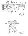
- Fig 1 shows in cross section one edge region of a rectilinear support frame moulded from a composite of glass reinforced plastics material of the type generally shown in Fig 24 of UK Patent Specification 2322590.
- the edge includes a flange 10 the upper face of which is ridged at 12, 14 etc., so that wire mesh laid thereon and pressed down with the application of heat, will sink into the softened crests of the ridges 12, 14 etc., and remain embedded therein when the composite material cools.
- the support frame is divided by a rectilinear array of perpendicularly crossing ribs arranged as rows and columns and formed integrally with the four edge flanges of the frame of which one is shown at 10.
- Fig 1 shows some of the ribs forming rows of the array denoted by 16, 18 etc., and the upper end of each is formed with a 60° ridge 20 (as best seen in Fig 2) which extends from two symmetrically slanting faces or lands 22, 24 at the upper end of the rib.
- Fig 3 Two of the transversely extending ribs 26, 28 are shown in Fig 3, the flat face of one of which is identified by reference numeral 28 in Fig 1.
- ribs 16, 18 etc. are cutaway as at 30 in rib 18 (and 32 in rib 19 in Fig 1).
- each rib 26, 28 etc. is, like the ribs 16, 18 etc., formed with a 60° ridge at 34 which extends along the length of the rib (26 in the case of Fig 4) from two symmetrical inclined faces or lands 36, 38.
- the ridges 20 and 34 are also formed from composite material which softens on being heated, so that under pressure, wire mesh stretched both the frame and the ribs will not only become embedded in the ridges such as 12, 14 etc., in the flanges along the sides and ends of the frame, but also in the ridges such as 20 and 34 along all of the ribs intersecting the frame and dividing the large opening therein into a large number of small similarly dimensioned rectangular openings or windows.
- a block 40 is provided such as shown in Fig 5, which is conveniently formed from resilient plastics material, or a composite of glass reinforced plastics material, for plugging one of the windows.
- the cross section profile of the block 40 is best seen in Fig 6 from which it will be noted that the upper section is of reduced width at 42 and along part of the length of the block.
- triangular cross section ridges 44, 46 are formed along opposite faces of the reduced width section.
- two such ridges 44 and 45 are formed along one face 48, and two similar ridges 46, 47 are formed along the opposite face 50, none of which can be seen in Fig 5, but which are visible in the plan view of Fig 7.
- each window such as formed by the ribs 16 and 18 are each provided with complementary triangular ridges on both sides of each rib, as shown at 52, 54 in the case of rib 16, and 56, 58 in the case of rib 18 in Fig 1.
- a block such as 40 is pushed upwardly from below until the ridges 44, 45 first snap over the ridge 56 on rib 18, and thereafter the ridges 46, 47 can be snapped over the ridge 54 on rib 16.
- the block is now held securely with its upper face in close contact with the damaged mesh extending over the window.
- the block 40 may be solid or hollow.
- a plurality of blocks such as 40 can be fitted to plug a corresponding number of the windows in a screen, until such time as the total area which has become blinded by the blocks is too great to allow the screen to remain in service.
- the invention provides a simpler and quicker method of replacing screens in situ, than hitherto.
- previous methods have required the screens to be removed and cleaned before damaged areas could be treated.
- Some previously proposed methods have required all the cloth stretched over one of the small windows in the support frame to be removed by cutting, to enable a piece of material to be let in and bonded in place to effect the repair. Again this was time consuming, and could be hazardous to the operator, given that the cut ends of the wire cloth are like the sharp ends of pins and without protective clothing the operator's hands could easily suffer cuts and abrasions.
Landscapes
- Combined Means For Separation Of Solids (AREA)
- Application Of Or Painting With Fluid Materials (AREA)
- Separation By Low-Temperature Treatments (AREA)
- Sewage (AREA)
- Electrolytic Production Of Metals (AREA)
- Diaphragms For Electromechanical Transducers (AREA)
- Chemical Treatment Of Metals (AREA)
- Manufacture, Treatment Of Glass Fibers (AREA)
- Formation Of Various Coating Films On Cathode Ray Tubes And Lamps (AREA)
- Photoreceptors In Electrophotography (AREA)
- Preparation Of Compounds By Using Micro-Organisms (AREA)
- Measuring Or Testing Involving Enzymes Or Micro-Organisms (AREA)
- Heating, Cooling, Or Curing Plastics Or The Like In General (AREA)
- Electrical Discharge Machining, Electrochemical Machining, And Combined Machining (AREA)
- Working Measures On Existing Buildindgs (AREA)
Abstract
Description
- This invention concerns screens which can be used as filters in industrial filtration equipment such as shakers that are used in the oil drilling industry for separating solids from the liquid phase of oil and water based muds retrieved from drilling operations. In particular the invention is concerned with a method and device for plugging small areas of the mesh of such screens which can become damaged in use.
- Filtering machines of this type are described in UK 2237521 and UK 2229771 and screens of the type are described in WO95/23655 and UK 2322590. Also WO92/00133 discloses a filter screen assembly in which damaged mesh is cut away and a module snap fitted in its place.
- As best seen from Figs 1, 11 and 24 of UK 2322590 it has become conventional practice to effectively divide up the mesh area by stretching and securing layers of mesh over a frame, the large opening in which is divided into a large number of similarly sized smaller windows by an orthogonal array of ribs. The mesh is secured to the ribs as well as to the surrounding frame, so that each area of unsupported mesh is relatively small and is defined by the area of each of the small windows defined by the ribs.
- Damage tends to be in the form of perforation of the mesh in one or more of the small unsupported areas of mesh, causing that area of the mesh to allow through larger particles than it should. Once this occurs the screen must be replaced or repaired.
- Since each small area only accounts for a small percentage of the overall throughput of filtered material, it is possible to block a number of windows in a screen before its throughput falls too much to enable it to continue to be used. It is known to patch such windows with a layer of quick-setting epoxy or other plastics or resin based material, which when cured forms an impenetrable film or coating over the window concerned. This prevents the escape of oversize particles through the window due to the opening in the mesh caused by the damage.
- It is an object of the present invention to provide an improved screen design and improved device and method for blocking off (i.e. plugging) windows in screens as aforesaid in this way.
- Reference to mesh herein means woven wire mesh and the invention is equally applicable to screens having a single layer of woven wire mesh or two or more layers of woven wire mesh stretched over and secured to the frame and ribs as above described.
- According to the present invention there is provided a method of plugging an area of damaged mesh in a sifting screen the upper surface of which is substantially flat and is comprised of mesh stretched and tensioned over, and bonded to, a generally flat upper surface of a supporting frame, and wherein the underside of a supporting frame is made up of intersecting orthogonal rows and columns of ribs defining rectangular windows in the frame wherein the damaged area is within the mesh stretched over one of the windows in the supporting frame, characterised by the step of: inserting into the said one window from the underside of the frame and beneath the mesh a closure device which is a close fit therein, and securing the device in the window so as to completely cover the area of damaged mesh and block the window, so that the window ceases to filter product and the blockage prevents solids from passing through the damaged mesh.
- The device may be a plate or block.
- Alternatively the device may comprise a former having stretched thereacross and secured thereto mesh similar to that stretched across the window in question.
- The device may be secured in place by a force fit in the window.
- Alternatively the device is secured may be place by an interference fit with the window.
- Alternatively the device may be secured in place by mechanical means.
- Alternatively the device may be secured in place by an adhesive.
- In a preferred embodiment the device is resiliently deformable to allow it to be pushed past at least one projection on at least one of the elements which define the window, so that the step of fitting the device so as to cover the damaged mesh in the window involves pushing the device into the window and snapping it into place.
- Where all the windows are of similar shape and size, only one design of device is required.
- Preferably side faces of the ribs are provided with lips which are parallel to but spaced from the underside of the mesh, and the device is adapted to be fitted in place by forcing at least part of it beyond the lips so that it snaps into place below the damaged mesh.
- The invention also lies in a sifting screen comprising a frame having a plurality of similarly sized rectilinear openings or windows defined by ribs and support tensioned mesh secured thereover during manufacture, characterised in that at least some of the inwardly facing walls of the ribs defining the openings or windows include at least one ridge or lip, spaced from the upper ends of the openings over which the mesh is to be secured; which are thereby adapted to receive and retain a rectilinear closure device having appropriate dimensions and formed with at least one complementary ridge or lip along corresponding sides to those of the openings which carry a ridge or lip, whereby the closure device is adapted to be pushed into an opening from the end thereof opposite to that which is covered by the mesh, and retained in place by engagement between the ridges or lips on the sides of the opening and those on the sides of the closure device, thereby to completely block the opening and prevent solids from passing therethrough in the event that the mesh secured thereover becomes damaged.
- The invention also lies in a rectilinear closure device, of plastics or reinforced plastics material, in combination with a sifting screen according to the preceding paragraph, wherein the closure device is adapted to be fitted into an opening in the sifting screen.
- The invention will now be described by way of example with reference to the accompanying drawings, in which:-
- Fig 1 is a cross section through an edge region of the frame of a rectilinear screen adapted to received plugging blocks for repair, in accordance with the present invention;
- Fig 2 is a cross section through the upper end of one of the ribs in the frame;
- Fig 3 is a cross section through a region of the screen and frame of Fig 1 at right angles to the view of Fig 1;
- Fig 4 is a cross section to an enlarged scale through the upper end of one of the transverse ribs of the frame of Fig 3;
- Fig 5 is a perspective view of a block for plugging a window in the frame of Fig 1 in accordance with the invention;
- Fig 6 is an end view of the block of Fig 5; and
- Fig 7 is a top plan view of the block of Fig 5.
- Fig 1 shows in cross section one edge region of a rectilinear support frame moulded from a composite of glass reinforced plastics material of the type generally shown in Fig 24 of UK Patent Specification 2322590. The edge includes a
flange 10 the upper face of which is ridged at 12, 14 etc., so that wire mesh laid thereon and pressed down with the application of heat, will sink into the softened crests of theridges - The support frame is divided by a rectilinear array of perpendicularly crossing ribs arranged as rows and columns and formed integrally with the four edge flanges of the frame of which one is shown at 10.
- Fig 1 shows some of the ribs forming rows of the array denoted by 16, 18 etc., and the upper end of each is formed with a 60° ridge 20 (as best seen in Fig 2) which extends from two symmetrically slanting faces or
lands - Two of the transversely extending
ribs reference numeral 28 in Fig 1. - Some of the
ribs rib 19 in Fig 1). - The cutaway is shown in elevation in Fig 3 where
flange 18 is shown viewed from the side in the direction of arrows III, III (see Fig 1). - The upper edge of each
rib ribs lands ridges - In accordance with the invention a
block 40 is provided such as shown in Fig 5, which is conveniently formed from resilient plastics material, or a composite of glass reinforced plastics material, for plugging one of the windows. The cross section profile of theblock 40 is best seen in Fig 6 from which it will be noted that the upper section is of reduced width at 42 and along part of the length of the block. On opposite faces of the reduced width section are formed triangularcross section ridges such ridges face 48, and twosimilar ridges opposite face 50, none of which can be seen in Fig 5, but which are visible in the plan view of Fig 7. - Likewise the longer sides of each window such as formed by the
ribs rib rib 18 in Fig 1. Thus if a window defined byribs ridges ridge 56 onrib 18, and thereafter theridges ridge 54 onrib 16. The block is now held securely with its upper face in close contact with the damaged mesh extending over the window. - By ensuring the
block 40 is a close fit within the opening, little or no liquid or solids will be able to migrate between ribs such as 16, 18, 26 and 28 and although that window will cease to filter product, it will not permit solids to pass through any damaged area of the mesh which registers with that window. - By arranging the ridges so that the inclined faces are first to engage and the perpendicular undersides engage after being snapped into place, there is little chance of a
block 40 from being dislodged even under considerable top loading during filtering or as a consequence of vibration. - The
block 40 may be solid or hollow. - Depending on acceptable lower levels of throughput, a plurality of blocks such as 40 can be fitted to plug a corresponding number of the windows in a screen, until such time as the total area which has become blinded by the blocks is too great to allow the screen to remain in service.
- The invention provides a simpler and quicker method of replacing screens in situ, than hitherto. Thus previous methods have required the screens to be removed and cleaned before damaged areas could be treated. Some previously proposed methods have required all the cloth stretched over one of the small windows in the support frame to be removed by cutting, to enable a piece of material to be let in and bonded in place to effect the repair. Again this was time consuming, and could be hazardous to the operator, given that the cut ends of the wire cloth are like the sharp ends of pins and without protective clothing the operator's hands could easily suffer cuts and abrasions.
Claims (9)
- A method of plugging an area of damaged mesh in a sifting screen (10) the upper surface of which is substantially flat and is comprised of mesh stretched and tensioned over, and bonded to, a generally flat upper surface of a supporting frame, and wherein the underside of a supporting frame is made up of intersecting orthogonal rows and columns of ribs (16, 18) defining rectangular windows in the frame wherein the damaged area is within the mesh stretched over one of the windows in the supporting frame, characterised by the step of: inserting into the said one window from the underside of the frame and beneath the mesh a closure device (40) which is a close fit therein, and securing the device in the window so as to completely cover the area of damaged mesh and block the window, so that the window ceases to filter product and the blockage prevents solids from passing through the damaged mesh.
- A method as claimed in claim 1 wherein the device (40) is a plate or block.
- A method as claimed in claim 1 or claim 2 wherein the device (40) is secured in place in the window by a force fit, interference fit, by mechanical means, or by an adhesive.
- A method as claimed in claim 1 or claim 2 wherein the device (40) is resiliently deformable to allow it to be pushed past at least one projection (52, 54) on at least one of the elements which define the window, so that the step of fitting the device so as to cover the damaged mesh in the window involves pushing the device into the window and snapping it into place.
- A method as claimed in any of claims 1 to 4 wherein all the windows are of similar shape and size so that only one design of device is required.
- A method as claimed in any of claims 1 to 5 wherein side faces of the ribs are provided with lips which are parallel to but spaced from the underside of the mesh, and the device is adapted to be fitted in place by forcing at least part of it beyond the lips so that is snaps into place below the damaged mesh.
- A method as claimed in claim 6 wherein the edges of the device are shaped so as to facilitate its insertion beyond the lips on the ribs, but are such that once in place, the edges of the device impede its movement in the reverse direction.
- A sifting screen comprising a frame having a plurality of similarly sized rectilinear openings or windows defined by ribs (16, 18) and support tensioned mesh secured thereover during manufacture, characterised in that at least some of the inwardly facing walls of the ribs defining the openings or windows include at least one ridge or lip (52, 54), spaced from the upper ends of the openings over which the mesh is to be secured; which are thereby adapted to receive and retain a rectilinear closure device (40) having appropriate dimensions and formed with at least one complementary ridge or lip (44-47) along corresponding sides to those of the openings which carry a ridge or lip, whereby the closure device is adapted to be pushed into an opening from the end thereof opposite to that which is covered by the mesh, and retained in place by engagement between the ridges or lips on the sides of the opening and those on the sides of the closure device, thereby to completely block the opening and prevent solids from passing therethrough in the event that the mesh secured thereover becomes damaged.
- A rectilinear closure device, of plastics or reinforced plastics material in combination with a sifting screen according to claim 8, wherein the closure device is adapted to be fitted into an opening in the frame of the sifting screen.
Applications Claiming Priority (2)
| Application Number | Priority Date | Filing Date | Title |
|---|---|---|---|
| GB0120863A GB0120863D0 (en) | 2001-08-29 | 2001-08-29 | Improved method of apparatus for repairing screens |
| GB0120863 | 2001-08-29 |
Publications (3)
| Publication Number | Publication Date |
|---|---|
| EP1293265A2 EP1293265A2 (en) | 2003-03-19 |
| EP1293265A3 EP1293265A3 (en) | 2003-05-14 |
| EP1293265B1 true EP1293265B1 (en) | 2007-03-21 |
Family
ID=9921118
Family Applications (1)
| Application Number | Title | Priority Date | Filing Date |
|---|---|---|---|
| EP20020254479 Expired - Lifetime EP1293265B1 (en) | 2001-08-29 | 2002-06-26 | Improved method and apparatus for repairing screens |
Country Status (15)
| Country | Link |
|---|---|
| US (1) | US6872466B2 (en) |
| EP (1) | EP1293265B1 (en) |
| JP (1) | JP4395289B2 (en) |
| CN (1) | CN1200780C (en) |
| AT (1) | ATE357296T1 (en) |
| AU (1) | AU2002300106B8 (en) |
| BR (1) | BR0203411B1 (en) |
| CA (1) | CA2393818C (en) |
| DE (1) | DE60218949T8 (en) |
| DK (1) | DK1293265T3 (en) |
| GB (2) | GB0120863D0 (en) |
| HK (1) | HK1055570A1 (en) |
| NO (1) | NO330873B1 (en) |
| SG (1) | SG120881A1 (en) |
| ZA (1) | ZA200205847B (en) |
Families Citing this family (15)
| Publication number | Priority date | Publication date | Assignee | Title |
|---|---|---|---|---|
| NO313845B1 (en) * | 2001-02-23 | 2002-12-09 | Thor Bjoernstad | Device for Õ extending the life of a sieve doll |
| GB2459049B (en) * | 2007-07-25 | 2009-12-16 | United Wire Ltd | Plugs for repairing sifting or filtering screens |
| GB2451264B (en) * | 2007-07-25 | 2012-03-28 | United Wire Ltd | Plugs for repairing sifting or filtering screens |
| KR101257389B1 (en) * | 2011-03-29 | 2013-04-23 | 현대제철 주식회사 | Emergency processing device for screen |
| GB2499223A (en) * | 2012-02-09 | 2013-08-14 | United Wire Ltd | Plugs for repairing sifting or filtering screens |
| CA2910273C (en) * | 2013-04-30 | 2018-05-29 | M-I Drilling Fluids Uk Ltd. | Screen having frame members with angled surface(s) |
| US9946806B2 (en) | 2013-05-07 | 2018-04-17 | Axure Software Solutions, Inc. | Exporting responsive designs from a graphical design tool |
| US9389759B2 (en) * | 2013-05-07 | 2016-07-12 | Axure Software Solutions, Inc. | Environment for responsive graphical designs |
| US8671352B1 (en) | 2013-05-07 | 2014-03-11 | Axure Software Solutions, Inc. | Variable dimension version editing for graphical designs |
| NO347457B1 (en) | 2013-07-25 | 2023-11-06 | M I Drilling Fluids Uk Ltd | System and method for modular filter screens |
| RU2663013C2 (en) * | 2013-10-22 | 2018-08-01 | Эм-Ай ДРИЛЛИНГ ФЛЮИДЗ ЮКей ЛТД. | System, apparatus and/or method for repairing sifting and/or filtering screens using plugs with a mesh layer |
| MX2017006196A (en) * | 2014-11-12 | 2017-12-04 | M I Drilling Fluids Uk Ltd | Plug for filtering screen. |
| US10369501B2 (en) | 2016-05-03 | 2019-08-06 | M-I Drilling Fluids Uk Ltd. | Apparatus, system and method for combining modular repair plugs |
| DE102016011817A1 (en) * | 2016-10-05 | 2018-04-05 | Hein, Lehmann Gmbh | Torque screening machine with optimized screen lining attachment |
| US10592589B1 (en) | 2018-08-21 | 2020-03-17 | Axure Software Solutions, Inc. | Multi-view masters for graphical designs |
Family Cites Families (14)
| Publication number | Priority date | Publication date | Assignee | Title |
|---|---|---|---|---|
| US3725271A (en) * | 1964-01-29 | 1973-04-03 | Giannotti Ass | Apparatus and method for separating particles from a flow of fluid |
| US5076924A (en) * | 1987-05-04 | 1991-12-31 | Hydrotech Nils-Ake Persson Ab | Filter plate |
| US5137622A (en) * | 1988-09-27 | 1992-08-11 | United Wire Limited | Filter screen assembly |
| GB2245191B (en) * | 1990-06-22 | 1994-01-26 | United Wire Ltd | Filter screen assembly |
| US5490598A (en) * | 1994-03-30 | 1996-02-13 | Drexel Oilfield Services, Inc. | Screen for vibrating separator |
| US5971159A (en) * | 1993-04-30 | 1999-10-26 | Tuboscope I/P, Inc. | Screen assembly for a vibratory separator |
| US6722504B2 (en) * | 1993-04-30 | 2004-04-20 | Varco I/P, Inc. | Vibratory separators and screens |
| GB9404071D0 (en) * | 1994-03-03 | 1994-04-20 | United Wire Ltd | Improved sifting screen |
| US6029824A (en) * | 1994-03-30 | 2000-02-29 | Tuboscope I/P, Inc. | Screen for vibrating separator |
| US5851393A (en) * | 1995-11-14 | 1998-12-22 | Emerson Electric Co. | Screen assembly |
| GB2337019B (en) * | 1997-03-01 | 2001-06-13 | United Wire Ltd | Improved filtering screen and support frame therefor |
| US6736270B2 (en) * | 1998-10-30 | 2004-05-18 | Varco I/P, Inc. | Glued screens for shale shakers |
| US6220449B1 (en) * | 1999-10-01 | 2001-04-24 | Tuboscope I/P, Inc. | Flat top cloth support screen |
| US6461513B1 (en) * | 2000-05-19 | 2002-10-08 | Filtration Solutions, Inc. | Secondary-flow enhanced filtration system |
-
2001
- 2001-08-29 GB GB0120863A patent/GB0120863D0/en not_active Ceased
-
2002
- 2002-06-26 DK DK02254479T patent/DK1293265T3/en active
- 2002-06-26 EP EP20020254479 patent/EP1293265B1/en not_active Expired - Lifetime
- 2002-06-26 GB GB0214777A patent/GB2379177C/en not_active Expired - Lifetime
- 2002-06-26 DE DE2002618949 patent/DE60218949T8/en active Active
- 2002-06-26 AT AT02254479T patent/ATE357296T1/en not_active IP Right Cessation
- 2002-07-08 US US10/191,357 patent/US6872466B2/en not_active Expired - Lifetime
- 2002-07-12 AU AU2002300106A patent/AU2002300106B8/en not_active Ceased
- 2002-07-16 CA CA 2393818 patent/CA2393818C/en not_active Expired - Lifetime
- 2002-07-22 ZA ZA200205847A patent/ZA200205847B/en unknown
- 2002-08-05 JP JP2002227063A patent/JP4395289B2/en not_active Expired - Fee Related
- 2002-08-19 SG SG200205015A patent/SG120881A1/en unknown
- 2002-08-27 NO NO20024087A patent/NO330873B1/en not_active IP Right Cessation
- 2002-08-28 BR BRPI0203411-5A patent/BR0203411B1/en not_active IP Right Cessation
- 2002-08-29 CN CNB021422869A patent/CN1200780C/en not_active Expired - Fee Related
-
2003
- 2003-09-19 HK HK03106734.5A patent/HK1055570A1/en unknown
Also Published As
| Publication number | Publication date |
|---|---|
| CA2393818A1 (en) | 2003-02-28 |
| SG120881A1 (en) | 2006-04-26 |
| JP4395289B2 (en) | 2010-01-06 |
| AU2002300106B2 (en) | 2006-08-24 |
| CA2393818C (en) | 2011-06-07 |
| HK1055570A1 (en) | 2004-01-16 |
| NO330873B1 (en) | 2011-08-01 |
| BR0203411A (en) | 2003-05-27 |
| DK1293265T3 (en) | 2007-07-16 |
| EP1293265A2 (en) | 2003-03-19 |
| DE60218949T8 (en) | 2008-03-20 |
| EP1293265A3 (en) | 2003-05-14 |
| GB2379177B (en) | 2003-09-24 |
| CN1401441A (en) | 2003-03-12 |
| GB0214777D0 (en) | 2002-08-07 |
| DE60218949T2 (en) | 2007-11-29 |
| DE60218949D1 (en) | 2007-05-03 |
| ATE357296T1 (en) | 2007-04-15 |
| AU2002300106B8 (en) | 2006-12-21 |
| GB0120863D0 (en) | 2001-10-17 |
| JP2003080172A (en) | 2003-03-18 |
| CN1200780C (en) | 2005-05-11 |
| US20030042190A1 (en) | 2003-03-06 |
| GB2379177A (en) | 2003-03-05 |
| ZA200205847B (en) | 2003-03-31 |
| US6872466B2 (en) | 2005-03-29 |
| NO20024087L (en) | 2003-03-03 |
| NO20024087D0 (en) | 2002-08-27 |
| GB2379177C (en) | 2011-10-26 |
| BR0203411B1 (en) | 2010-12-28 |
Similar Documents
| Publication | Publication Date | Title |
|---|---|---|
| US6872466B2 (en) | Method and apparatus for repairing screens | |
| US5137622A (en) | Filter screen assembly | |
| AU639117B2 (en) | Filter screen assembly | |
| EP1179357B1 (en) | Screen assembly, vibratory separator and method of screening | |
| EP1002588B1 (en) | Panel for a screen | |
| US4347129A (en) | Screening module | |
| EP0359878A1 (en) | Filter screen assembly | |
| CA2419155C (en) | A screen assembly for a vibratory separator | |
| RU2414967C2 (en) | Sifting device | |
| US20200230653A1 (en) | Screening Material and Screen Assembly | |
| RU2663013C2 (en) | System, apparatus and/or method for repairing sifting and/or filtering screens using plugs with a mesh layer | |
| EP1615728B1 (en) | Filtering screen | |
| CA1184538A (en) | Screen |
Legal Events
| Date | Code | Title | Description |
|---|---|---|---|
| PUAI | Public reference made under article 153(3) epc to a published international application that has entered the european phase |
Free format text: ORIGINAL CODE: 0009012 |
|
| AK | Designated contracting states |
Kind code of ref document: A2 Designated state(s): AT BE CH CY DE DK ES FI FR GB GR IE IT LI LU MC NL PT SE TR Designated state(s): AT BE CH CY DE DK ES FI FR GB GR IE IT LI LU MC NL PT SE TR |
|
| AX | Request for extension of the european patent |
Extension state: AL LT LV MK RO SI |
|
| PUAL | Search report despatched |
Free format text: ORIGINAL CODE: 0009013 |
|
| AK | Designated contracting states |
Designated state(s): AT BE CH CY DE DK ES FI FR GB GR IE IT LI LU MC NL PT SE TR |
|
| AX | Request for extension of the european patent |
Extension state: AL LT LV MK RO SI |
|
| 17P | Request for examination filed |
Effective date: 20030522 |
|
| AKX | Designation fees paid |
Designated state(s): AT BE CH CY DE DK ES FI FR GB GR IE IT LI LU MC NL PT SE TR |
|
| 17Q | First examination report despatched |
Effective date: 20060109 |
|
| GRAP | Despatch of communication of intention to grant a patent |
Free format text: ORIGINAL CODE: EPIDOSNIGR1 |
|
| GRAS | Grant fee paid |
Free format text: ORIGINAL CODE: EPIDOSNIGR3 |
|
| GRAA | (expected) grant |
Free format text: ORIGINAL CODE: 0009210 |
|
| AK | Designated contracting states |
Kind code of ref document: B1 Designated state(s): AT BE CH CY DE DK ES FI FR GB GR IE IT LI LU MC NL PT SE TR |
|
| PG25 | Lapsed in a contracting state [announced via postgrant information from national office to epo] |
Ref country code: LI Free format text: LAPSE BECAUSE OF FAILURE TO SUBMIT A TRANSLATION OF THE DESCRIPTION OR TO PAY THE FEE WITHIN THE PRESCRIBED TIME-LIMIT Effective date: 20070321 Ref country code: CH Free format text: LAPSE BECAUSE OF FAILURE TO SUBMIT A TRANSLATION OF THE DESCRIPTION OR TO PAY THE FEE WITHIN THE PRESCRIBED TIME-LIMIT Effective date: 20070321 Ref country code: FI Free format text: LAPSE BECAUSE OF FAILURE TO SUBMIT A TRANSLATION OF THE DESCRIPTION OR TO PAY THE FEE WITHIN THE PRESCRIBED TIME-LIMIT Effective date: 20070321 |
|
| REG | Reference to a national code |
Ref country code: GB Ref legal event code: FG4D |
|
| REG | Reference to a national code |
Ref country code: CH Ref legal event code: EP |
|
| REF | Corresponds to: |
Ref document number: 60218949 Country of ref document: DE Date of ref document: 20070503 Kind code of ref document: P |
|
| REG | Reference to a national code |
Ref country code: IE Ref legal event code: FG4D |
|
| PG25 | Lapsed in a contracting state [announced via postgrant information from national office to epo] |
Ref country code: SE Free format text: LAPSE BECAUSE OF FAILURE TO SUBMIT A TRANSLATION OF THE DESCRIPTION OR TO PAY THE FEE WITHIN THE PRESCRIBED TIME-LIMIT Effective date: 20070621 |
|
| PGFP | Annual fee paid to national office [announced via postgrant information from national office to epo] |
Ref country code: ES Payment date: 20070704 Year of fee payment: 6 |
|
| REG | Reference to a national code |
Ref country code: DK Ref legal event code: T3 |
|
| PG25 | Lapsed in a contracting state [announced via postgrant information from national office to epo] |
Ref country code: PT Free format text: LAPSE BECAUSE OF FAILURE TO SUBMIT A TRANSLATION OF THE DESCRIPTION OR TO PAY THE FEE WITHIN THE PRESCRIBED TIME-LIMIT Effective date: 20070821 |
|
| ET | Fr: translation filed | ||
| REG | Reference to a national code |
Ref country code: CH Ref legal event code: PL |
|
| PLBE | No opposition filed within time limit |
Free format text: ORIGINAL CODE: 0009261 |
|
| STAA | Information on the status of an ep patent application or granted ep patent |
Free format text: STATUS: NO OPPOSITION FILED WITHIN TIME LIMIT |
|
| PG25 | Lapsed in a contracting state [announced via postgrant information from national office to epo] |
Ref country code: MC Free format text: LAPSE BECAUSE OF NON-PAYMENT OF DUE FEES Effective date: 20070630 |
|
| 26N | No opposition filed |
Effective date: 20071227 |
|
| PG25 | Lapsed in a contracting state [announced via postgrant information from national office to epo] |
Ref country code: GR Free format text: LAPSE BECAUSE OF FAILURE TO SUBMIT A TRANSLATION OF THE DESCRIPTION OR TO PAY THE FEE WITHIN THE PRESCRIBED TIME-LIMIT Effective date: 20070622 |
|
| PG25 | Lapsed in a contracting state [announced via postgrant information from national office to epo] |
Ref country code: CY Free format text: LAPSE BECAUSE OF FAILURE TO SUBMIT A TRANSLATION OF THE DESCRIPTION OR TO PAY THE FEE WITHIN THE PRESCRIBED TIME-LIMIT Effective date: 20070321 |
|
| PGFP | Annual fee paid to national office [announced via postgrant information from national office to epo] |
Ref country code: DK Payment date: 20090511 Year of fee payment: 8 Ref country code: IE Payment date: 20090423 Year of fee payment: 8 |
|
| PG25 | Lapsed in a contracting state [announced via postgrant information from national office to epo] |
Ref country code: LU Free format text: LAPSE BECAUSE OF NON-PAYMENT OF DUE FEES Effective date: 20070626 |
|
| PGFP | Annual fee paid to national office [announced via postgrant information from national office to epo] |
Ref country code: FR Payment date: 20090605 Year of fee payment: 8 |
|
| PG25 | Lapsed in a contracting state [announced via postgrant information from national office to epo] |
Ref country code: TR Free format text: LAPSE BECAUSE OF FAILURE TO SUBMIT A TRANSLATION OF THE DESCRIPTION OR TO PAY THE FEE WITHIN THE PRESCRIBED TIME-LIMIT Effective date: 20070321 |
|
| REG | Reference to a national code |
Ref country code: HK Ref legal event code: WD Ref document number: 1055570 Country of ref document: HK |
|
| REG | Reference to a national code |
Ref country code: DK Ref legal event code: EBP |
|
| REG | Reference to a national code |
Ref country code: FR Ref legal event code: ST Effective date: 20110228 |
|
| PG25 | Lapsed in a contracting state [announced via postgrant information from national office to epo] |
Ref country code: IE Free format text: LAPSE BECAUSE OF NON-PAYMENT OF DUE FEES Effective date: 20100628 |
|
| PG25 | Lapsed in a contracting state [announced via postgrant information from national office to epo] |
Ref country code: FR Free format text: LAPSE BECAUSE OF NON-PAYMENT OF DUE FEES Effective date: 20100630 Ref country code: AT Free format text: LAPSE BECAUSE OF NON-PAYMENT OF DUE FEES Effective date: 20100626 |
|
| PG25 | Lapsed in a contracting state [announced via postgrant information from national office to epo] |
Ref country code: DK Free format text: LAPSE BECAUSE OF NON-PAYMENT OF DUE FEES Effective date: 20100630 |
|
| PG25 | Lapsed in a contracting state [announced via postgrant information from national office to epo] |
Ref country code: ES Free format text: THE PATENT HAS BEEN ANNULLED BY A DECISION OF A NATIONAL AUTHORITY Effective date: 20070702 |
|
| PGFP | Annual fee paid to national office [announced via postgrant information from national office to epo] |
Ref country code: IT Payment date: 20140611 Year of fee payment: 13 |
|
| PGFP | Annual fee paid to national office [announced via postgrant information from national office to epo] |
Ref country code: BE Payment date: 20140611 Year of fee payment: 13 |
|
| PG25 | Lapsed in a contracting state [announced via postgrant information from national office to epo] |
Ref country code: IT Free format text: LAPSE BECAUSE OF NON-PAYMENT OF DUE FEES Effective date: 20150626 |
|
| PG25 | Lapsed in a contracting state [announced via postgrant information from national office to epo] |
Ref country code: BE Free format text: LAPSE BECAUSE OF NON-PAYMENT OF DUE FEES Effective date: 20150630 |
|
| PGFP | Annual fee paid to national office [announced via postgrant information from national office to epo] |
Ref country code: AT Payment date: 20190522 Year of fee payment: 13 |
|
| REG | Reference to a national code |
Ref country code: DE Ref legal event code: R119 Ref document number: 60218949 Country of ref document: DE |
|
| PG25 | Lapsed in a contracting state [announced via postgrant information from national office to epo] |
Ref country code: DE Free format text: LAPSE BECAUSE OF NON-PAYMENT OF DUE FEES Effective date: 20210101 |
|
| PGFP | Annual fee paid to national office [announced via postgrant information from national office to epo] |
Ref country code: NL Payment date: 20210615 Year of fee payment: 20 |
|
| PGFP | Annual fee paid to national office [announced via postgrant information from national office to epo] |
Ref country code: GB Payment date: 20210603 Year of fee payment: 20 |
|
| REG | Reference to a national code |
Ref country code: NL Ref legal event code: MK Effective date: 20220625 |
|
| REG | Reference to a national code |
Ref country code: GB Ref legal event code: PE20 Expiry date: 20220625 |
|
| PG25 | Lapsed in a contracting state [announced via postgrant information from national office to epo] |
Ref country code: GB Free format text: LAPSE BECAUSE OF EXPIRATION OF PROTECTION Effective date: 20220625 |