EP1293257A1 - Liquid droplet ejecting device and liquid droplet ejecting method - Google Patents
Liquid droplet ejecting device and liquid droplet ejecting method Download PDFInfo
- Publication number
- EP1293257A1 EP1293257A1 EP01941088A EP01941088A EP1293257A1 EP 1293257 A1 EP1293257 A1 EP 1293257A1 EP 01941088 A EP01941088 A EP 01941088A EP 01941088 A EP01941088 A EP 01941088A EP 1293257 A1 EP1293257 A1 EP 1293257A1
- Authority
- EP
- European Patent Office
- Prior art keywords
- ejection
- liquid
- bore
- pressurizing chamber
- liquid droplet
- Prior art date
- Legal status (The legal status is an assumption and is not a legal conclusion. Google has not performed a legal analysis and makes no representation as to the accuracy of the status listed.)
- Withdrawn
Links
- 239000007788 liquid Substances 0.000 title claims abstract description 240
- 238000000034 method Methods 0.000 title claims description 4
- 239000000919 ceramic Substances 0.000 claims abstract description 28
- 230000008859 change Effects 0.000 claims abstract description 25
- 239000005871 repellent Substances 0.000 claims description 13
- MCMNRKCIXSYSNV-UHFFFAOYSA-N Zirconium dioxide Chemical compound O=[Zr]=O MCMNRKCIXSYSNV-UHFFFAOYSA-N 0.000 claims description 12
- 230000007423 decrease Effects 0.000 claims description 8
- 238000004891 communication Methods 0.000 abstract description 4
- 230000005684 electric field Effects 0.000 description 5
- 239000000446 fuel Substances 0.000 description 4
- 230000006735 deficit Effects 0.000 description 3
- 238000002474 experimental method Methods 0.000 description 3
- 230000007547 defect Effects 0.000 description 2
- 230000002708 enhancing effect Effects 0.000 description 2
- 230000001747 exhibiting effect Effects 0.000 description 2
- 230000004044 response Effects 0.000 description 2
- YCKRFDGAMUMZLT-UHFFFAOYSA-N Fluorine atom Chemical compound [F] YCKRFDGAMUMZLT-UHFFFAOYSA-N 0.000 description 1
- 230000009471 action Effects 0.000 description 1
- 230000004913 activation Effects 0.000 description 1
- 238000002485 combustion reaction Methods 0.000 description 1
- 230000008602 contraction Effects 0.000 description 1
- 239000012530 fluid Substances 0.000 description 1
- 229910052731 fluorine Inorganic materials 0.000 description 1
- 239000011737 fluorine Substances 0.000 description 1
- 238000002347 injection Methods 0.000 description 1
- 239000007924 injection Substances 0.000 description 1
- 239000011344 liquid material Substances 0.000 description 1
- 238000004519 manufacturing process Methods 0.000 description 1
- 239000003595 mist Substances 0.000 description 1
- 230000004048 modification Effects 0.000 description 1
- 238000012986 modification Methods 0.000 description 1
- 230000010287 polarization Effects 0.000 description 1
- 239000000843 powder Substances 0.000 description 1
- 238000004080 punching Methods 0.000 description 1
- 239000011347 resin Substances 0.000 description 1
- 229920005989 resin Polymers 0.000 description 1
Images



Classifications
-
- F—MECHANICAL ENGINEERING; LIGHTING; HEATING; WEAPONS; BLASTING
- F02—COMBUSTION ENGINES; HOT-GAS OR COMBUSTION-PRODUCT ENGINE PLANTS
- F02M—SUPPLYING COMBUSTION ENGINES IN GENERAL WITH COMBUSTIBLE MIXTURES OR CONSTITUENTS THEREOF
- F02M61/00—Fuel-injectors not provided for in groups F02M39/00 - F02M57/00 or F02M67/00
- F02M61/16—Details not provided for in, or of interest apart from, the apparatus of groups F02M61/02 - F02M61/14
- F02M61/18—Injection nozzles, e.g. having valve seats; Details of valve member seated ends, not otherwise provided for
- F02M61/1806—Injection nozzles, e.g. having valve seats; Details of valve member seated ends, not otherwise provided for characterised by the arrangement of discharge orifices, e.g. orientation or size
- F02M61/1846—Dimensional characteristics of discharge orifices
-
- B—PERFORMING OPERATIONS; TRANSPORTING
- B05—SPRAYING OR ATOMISING IN GENERAL; APPLYING FLUENT MATERIALS TO SURFACES, IN GENERAL
- B05B—SPRAYING APPARATUS; ATOMISING APPARATUS; NOZZLES
- B05B17/00—Apparatus for spraying or atomising liquids or other fluent materials, not covered by the preceding groups
- B05B17/04—Apparatus for spraying or atomising liquids or other fluent materials, not covered by the preceding groups operating with special methods
- B05B17/06—Apparatus for spraying or atomising liquids or other fluent materials, not covered by the preceding groups operating with special methods using ultrasonic or other kinds of vibrations
- B05B17/0607—Apparatus for spraying or atomising liquids or other fluent materials, not covered by the preceding groups operating with special methods using ultrasonic or other kinds of vibrations generated by electrical means, e.g. piezoelectric transducers
-
- F—MECHANICAL ENGINEERING; LIGHTING; HEATING; WEAPONS; BLASTING
- F02—COMBUSTION ENGINES; HOT-GAS OR COMBUSTION-PRODUCT ENGINE PLANTS
- F02M—SUPPLYING COMBUSTION ENGINES IN GENERAL WITH COMBUSTIBLE MIXTURES OR CONSTITUENTS THEREOF
- F02M51/00—Fuel-injection apparatus characterised by being operated electrically
- F02M51/04—Pumps peculiar thereto
-
- F—MECHANICAL ENGINEERING; LIGHTING; HEATING; WEAPONS; BLASTING
- F02—COMBUSTION ENGINES; HOT-GAS OR COMBUSTION-PRODUCT ENGINE PLANTS
- F02M—SUPPLYING COMBUSTION ENGINES IN GENERAL WITH COMBUSTIBLE MIXTURES OR CONSTITUENTS THEREOF
- F02M51/00—Fuel-injection apparatus characterised by being operated electrically
- F02M51/06—Injectors peculiar thereto with means directly operating the valve needle
- F02M51/0603—Injectors peculiar thereto with means directly operating the valve needle using piezoelectric or magnetostrictive operating means
-
- F—MECHANICAL ENGINEERING; LIGHTING; HEATING; WEAPONS; BLASTING
- F02—COMBUSTION ENGINES; HOT-GAS OR COMBUSTION-PRODUCT ENGINE PLANTS
- F02M—SUPPLYING COMBUSTION ENGINES IN GENERAL WITH COMBUSTIBLE MIXTURES OR CONSTITUENTS THEREOF
- F02M57/00—Fuel-injectors combined or associated with other devices
- F02M57/02—Injectors structurally combined with fuel-injection pumps
- F02M57/021—Injectors structurally combined with fuel-injection pumps the injector being of valveless type, e.g. the pump piston co-operating with a conical seat of an injection nozzle at the end of the pumping stroke
-
- F—MECHANICAL ENGINEERING; LIGHTING; HEATING; WEAPONS; BLASTING
- F02—COMBUSTION ENGINES; HOT-GAS OR COMBUSTION-PRODUCT ENGINE PLANTS
- F02M—SUPPLYING COMBUSTION ENGINES IN GENERAL WITH COMBUSTIBLE MIXTURES OR CONSTITUENTS THEREOF
- F02M57/00—Fuel-injectors combined or associated with other devices
- F02M57/02—Injectors structurally combined with fuel-injection pumps
- F02M57/022—Injectors structurally combined with fuel-injection pumps characterised by the pump drive
- F02M57/027—Injectors structurally combined with fuel-injection pumps characterised by the pump drive electric
-
- F—MECHANICAL ENGINEERING; LIGHTING; HEATING; WEAPONS; BLASTING
- F02—COMBUSTION ENGINES; HOT-GAS OR COMBUSTION-PRODUCT ENGINE PLANTS
- F02M—SUPPLYING COMBUSTION ENGINES IN GENERAL WITH COMBUSTIBLE MIXTURES OR CONSTITUENTS THEREOF
- F02M61/00—Fuel-injectors not provided for in groups F02M39/00 - F02M57/00 or F02M67/00
- F02M61/16—Details not provided for in, or of interest apart from, the apparatus of groups F02M61/02 - F02M61/14
- F02M61/166—Selection of particular materials
-
- F—MECHANICAL ENGINEERING; LIGHTING; HEATING; WEAPONS; BLASTING
- F02—COMBUSTION ENGINES; HOT-GAS OR COMBUSTION-PRODUCT ENGINE PLANTS
- F02M—SUPPLYING COMBUSTION ENGINES IN GENERAL WITH COMBUSTIBLE MIXTURES OR CONSTITUENTS THEREOF
- F02M61/00—Fuel-injectors not provided for in groups F02M39/00 - F02M57/00 or F02M67/00
- F02M61/16—Details not provided for in, or of interest apart from, the apparatus of groups F02M61/02 - F02M61/14
- F02M61/18—Injection nozzles, e.g. having valve seats; Details of valve member seated ends, not otherwise provided for
-
- F—MECHANICAL ENGINEERING; LIGHTING; HEATING; WEAPONS; BLASTING
- F02—COMBUSTION ENGINES; HOT-GAS OR COMBUSTION-PRODUCT ENGINE PLANTS
- F02M—SUPPLYING COMBUSTION ENGINES IN GENERAL WITH COMBUSTIBLE MIXTURES OR CONSTITUENTS THEREOF
- F02M61/00—Fuel-injectors not provided for in groups F02M39/00 - F02M57/00 or F02M67/00
- F02M61/16—Details not provided for in, or of interest apart from, the apparatus of groups F02M61/02 - F02M61/14
- F02M61/18—Injection nozzles, e.g. having valve seats; Details of valve member seated ends, not otherwise provided for
- F02M61/1806—Injection nozzles, e.g. having valve seats; Details of valve member seated ends, not otherwise provided for characterised by the arrangement of discharge orifices, e.g. orientation or size
- F02M61/1833—Discharge orifices having changing cross sections, e.g. being divergent
-
- F—MECHANICAL ENGINEERING; LIGHTING; HEATING; WEAPONS; BLASTING
- F02—COMBUSTION ENGINES; HOT-GAS OR COMBUSTION-PRODUCT ENGINE PLANTS
- F02M—SUPPLYING COMBUSTION ENGINES IN GENERAL WITH COMBUSTIBLE MIXTURES OR CONSTITUENTS THEREOF
- F02M61/00—Fuel-injectors not provided for in groups F02M39/00 - F02M57/00 or F02M67/00
- F02M61/16—Details not provided for in, or of interest apart from, the apparatus of groups F02M61/02 - F02M61/14
- F02M61/18—Injection nozzles, e.g. having valve seats; Details of valve member seated ends, not otherwise provided for
- F02M61/1853—Orifice plates
- F02M61/186—Multi-layered orifice plates
-
- F—MECHANICAL ENGINEERING; LIGHTING; HEATING; WEAPONS; BLASTING
- F02—COMBUSTION ENGINES; HOT-GAS OR COMBUSTION-PRODUCT ENGINE PLANTS
- F02M—SUPPLYING COMBUSTION ENGINES IN GENERAL WITH COMBUSTIBLE MIXTURES OR CONSTITUENTS THEREOF
- F02M2200/00—Details of fuel-injection apparatus, not otherwise provided for
- F02M2200/90—Selection of particular materials
-
- F—MECHANICAL ENGINEERING; LIGHTING; HEATING; WEAPONS; BLASTING
- F02—COMBUSTION ENGINES; HOT-GAS OR COMBUSTION-PRODUCT ENGINE PLANTS
- F02M—SUPPLYING COMBUSTION ENGINES IN GENERAL WITH COMBUSTIBLE MIXTURES OR CONSTITUENTS THEREOF
- F02M2200/00—Details of fuel-injection apparatus, not otherwise provided for
- F02M2200/90—Selection of particular materials
- F02M2200/9007—Ceramic materials
-
- F—MECHANICAL ENGINEERING; LIGHTING; HEATING; WEAPONS; BLASTING
- F02—COMBUSTION ENGINES; HOT-GAS OR COMBUSTION-PRODUCT ENGINE PLANTS
- F02M—SUPPLYING COMBUSTION ENGINES IN GENERAL WITH COMBUSTIBLE MIXTURES OR CONSTITUENTS THEREOF
- F02M2200/00—Details of fuel-injection apparatus, not otherwise provided for
- F02M2200/90—Selection of particular materials
- F02M2200/9015—Elastomeric or plastic materials
-
- F—MECHANICAL ENGINEERING; LIGHTING; HEATING; WEAPONS; BLASTING
- F02—COMBUSTION ENGINES; HOT-GAS OR COMBUSTION-PRODUCT ENGINE PLANTS
- F02M—SUPPLYING COMBUSTION ENGINES IN GENERAL WITH COMBUSTIBLE MIXTURES OR CONSTITUENTS THEREOF
- F02M2200/00—Details of fuel-injection apparatus, not otherwise provided for
- F02M2200/90—Selection of particular materials
- F02M2200/9038—Coatings
-
- F—MECHANICAL ENGINEERING; LIGHTING; HEATING; WEAPONS; BLASTING
- F02—COMBUSTION ENGINES; HOT-GAS OR COMBUSTION-PRODUCT ENGINE PLANTS
- F02M—SUPPLYING COMBUSTION ENGINES IN GENERAL WITH COMBUSTIBLE MIXTURES OR CONSTITUENTS THEREOF
- F02M2200/00—Details of fuel-injection apparatus, not otherwise provided for
- F02M2200/90—Selection of particular materials
- F02M2200/9046—Multi-layered materials
-
- F—MECHANICAL ENGINEERING; LIGHTING; HEATING; WEAPONS; BLASTING
- F02—COMBUSTION ENGINES; HOT-GAS OR COMBUSTION-PRODUCT ENGINE PLANTS
- F02M—SUPPLYING COMBUSTION ENGINES IN GENERAL WITH COMBUSTIBLE MIXTURES OR CONSTITUENTS THEREOF
- F02M61/00—Fuel-injectors not provided for in groups F02M39/00 - F02M57/00 or F02M67/00
- F02M61/16—Details not provided for in, or of interest apart from, the apparatus of groups F02M61/02 - F02M61/14
- F02M61/168—Assembling; Disassembling; Manufacturing; Adjusting
Definitions
- the present invention relates to a liquid droplet ejection apparatus for ejecting droplets of liquid, such as liquid material or fluid, from an ejection opening through pressurization of the liquid within a pressurizing chamber.
- liquid such as liquid material or fluid
- the liquid droplet ejection apparatus of this type includes a pressurizing chamber into which liquid is introduced via a liquid introduction bore, an ejection nozzle communicating with the pressurizing chamber, and pressurizing means, such as a piezoelectric/electrostrictive element, for changing the volume of the pressurizing chamber.
- the apparatus pressurizes liquid contained in the pressurizing chamber through change in the volume of the pressurizing chamber to thereby eject the liquid in the form of droplets from an ejection opening of the ejection nozzle.
- Such a liquid droplet ejection apparatus is used in, for example, a color printer.
- An object of the present invention is to provide a liquid droplet ejection apparatus capable of ejecting liquid in a mistlike form.
- the present invention provides a liquid droplet ejection apparatus comprising a pressurizing chamber communicating with a liquid supply path via a liquid introduction bore assuming a hollow cylindrical form, an ejection nozzle including an ejection bore which is connected to the pressurizing chamber and whose end portion assumes a hollow cylindrical form having a bottom face serving as an ejection opening, and a piezoelectric/electrostrictive element for changing the volume of the pressurizing chamber.
- the liquid droplet ejection apparatus pressurizes, by means of a change in the volume of the pressurizing chamber, liquid introduced into the pressurizing chamber via the liquid introduction bore to thereby eject the liquid in the form of liquid droplets from the circular ejection opening of the ejection bore.
- the liquid droplet ejection apparatus is configured such that the diameter of the largest liquid droplet among liquid droplets ejected is not greater than the diameter of the ejection opening.
- the present invention provides a similar liquid droplet ejection apparatus configured such that a plurality of liquid droplets are simultaneously ejected from the ejection opening by means of a single operation of pressurization.
- the present invention provides a similar liquid droplet ejection apparatus configured such that a plurality of liquid droplets ejected from the ejection opening by means of a single operation of pressurization simultaneously reach an imaginary plane defined in a manner such that all points on the plane maintain an equal distance to the ejection opening.
- liquid droplet ejection apparatuses can be used in mechanical equipment requiring mistlike fuel or the like (e.g., a gasoline-injection-type internal combustion engine) and eject (inject) liquid through effective utilization of a piezoelectric/electrostrictive element.
- a hollow cylindrical form means "a hollow, substantially cylindrical form.” Accordingly, a hollow cylindrical form includes "a hollow, truncated cone.”
- any one of the liquid droplet ejection apparatuses described above is configured such that the ratio of the diameter of the liquid introduction bore to the diameter of the ejection opening is 0.6 to 1.6; the ratio of the diameter of the ejection opening to the height of the hollow cylinder forming the ejection bore located at the end portion of the ejection nozzle is 0.2 to 4; and the rate of change (per unit time) in the ratio of the amount of change in the volume of the pressurizing chamber to the sum of the volume of the ejection nozzle and the volume of the pressurizing chamber is 6 ppm/ ⁇ s to 40 ppm/ ⁇ s.
- the ratio of the diameter d0 of the liquid introduction bore to the diameter d1 of the ejection opening (d0/d1) is 0.6 to 1.6 for the following reason.
- the ratio (d0/d1) is less than 0.6, the amount of liquid to be introduced into the pressurizing chamber via the liquid introduction bore becomes small in relation to the amount of liquid to be ejected from the ejection opening, causing an ejection defect.
- the ratio (d0/d1) is in excess of 1.6, during pressurization, a large amount of liquid flows back into the liquid supply path from the pressurizing chamber via the liquid introduction bore, resulting in a failure to eject liquid from the ejection opening.
- the ratio of the diameter d1 of the ejection opening i.e., the diameter d1 of the bottom face of the hollow cylinder
- the height h1 of the hollow cylinder forming the ejection bore located at the end portion of the ejection nozzle (d1/h1) is 0.2 to 4 for the following reason.
- the ratio (d1/h1) is not greater than 4
- contact resistance between liquid and the inside wall surface of the end portion of the ejection nozzle becomes relatively large, so that vibration remaining, on liquid surface, immediately after ejection settles promptly, thereby preventing air (a bubble) from being caught in the ejection nozzle.
- the rate of change (per unit time) R in the ratio of the amount of change ⁇ V in the volume of the pressurizing chamber to the sum of the volume Vn of the ejection nozzle and the volume Vk of the pressurizing chamber ( ⁇ V/(Vn + Vk)) is 6 ppm/ ⁇ s to 40 ppm/ ⁇ s for the following reason.
- the greater the rate of change R the smaller liquid droplets become.
- the rate of change R is in excess of 40 ppm/ ⁇ s, ejection becomes unstable.
- the rate of change R is less than 6 ppm/ ⁇ s, droplets to be ejected become granular. As a result, an object that a plurality of liquid droplets are ejected by means of a single operation of pressurization cannot be attained.
- any one of the liquid droplet ejection apparatuses described above is configured such that the inside diameter of the hollow cylinder forming the ejection bore located at the end portion of the ejection nozzle increases toward the ejection opening.
- a value obtained by dividing, by the height h1 of the hollow cylinder, the difference between the diameter d1 of the bottom face of the hollow cylinder forming the ejection bore located at the end portion of the ejection nozzle and the diameter d2 of the top face of the hollow cylinder serving as an opening located on the side of the pressurizing chamber ((d1 - d2)/h1) is 0.05 to 0.7.
- the liquid is ejected in a mistlike form for the following reason.
- the liquid is subjected to not only a force imposed along the axial direction of the hollow cylinder (i.e., along the direction perpendicular to a plane serving as the ejection opening), but also a force imposed along a direction perpendicular to the axial direction and exerted from the inside wall surface of the hollow cylinder; thus, the liquid becomes unlikely to assume a large granular form.
- the ejection bore located at the end portion of the ejection nozzle comprises a first ejection bore formed in a thin-plate member and assuming a hollow cylindrical form having a top face located on the side of the pressurizing chamber and a bottom face located on the side of the ejection opening; and a second ejection bore assuming a hollow cylindrical form and formed in a liquid-repellent layer formed on the surface of the thin-plate member located on the side of the ejection opening, a top face of the hollow cylinder forming an opening connected to the bottom face of the first ejection bore, a bottom face of the hollow cylinder forming the ejection opening of the ejection nozzle.
- the inside diameter of the second ejection bore increases toward the ejection opening.
- a value obtained by dividing, by the height h2 of the second ejection bore, the difference between the diameter d3 of the ejection opening of the second ejection bore and the diameter d4 of the opening of the second ejection bore connected to the first ejection bore ((d3 -d4)/h2) is 0.5 to 2.0.
- the liquid-repellent layer is provided in order to prevent adhesion of liquid droplets to an area around the ejection opening during ejection.
- the liquid-repellent layer substantially serves as the end portion of the ejection nozzle. Accordingly, when, as mentioned above, the hollow cylindrical second ejection bore formed in the liquid-repellent layer is configured such that the inside diameter thereof increases toward the ejection opening, the liquid is subjected to not only a force imposed along the axial direction of the second ejection bore (hollow cylinder), but also a force imposed along a direction perpendicular to the axial direction; thus, the liquid becomes unlikely to assume a granular form. As a result, the liquid is ejected in a mistlike form.
- the inside diameter of the first ejection bore decreases toward the second ejection bore.
- a protrusion portion is formed on the inside wall surface of the ejection bore.
- the ratio of the height t of the protrusion portion to the diameter d6 of the ejection opening (t/d6) is 0.03 to 0.17.
- the protrusion portions are formed in an amount of 3 to 12.
- the protrusion portions split a liquid droplet immediately before ejection, thereby facilitating ejection of liquid in a mistlike form.
- the pressurizing chamber and the ejection nozzle are integrally formed of zirconia ceramics.
- piezoelectric/electrostrictive means piezoelectric and/or electrostrictive.
- the piezoelectric/electrostrictive element is widely known as an element characterized by extending primarily in a direction parallel to an externally applied electric field and contracting in a direction perpendicular to the electric field and adapted to convert electrical energy to mechanical energy and vice versa.
- a piezoelectric element is characterized by exhibiting coercive electric field (external electric field as observed upon inversion of polarization) of relatively high intensity.
- An electrostrictive element is characterized by exhibiting coercive electric field of very low intensity.
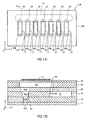
- FIG. 1A is a plan view of a liquid droplet ejection apparatus 10 according to a first embodiment of the present invention.
- FIG. 1B is a sectional view of the liquid droplet ejection apparatus 10 taken along line 1-1 of FIG. 1A.
- the liquid droplet ejection apparatus 10 is formed such that a plurality of ceramic thin-plate members (hereinafter called “ceramic sheets”) 11-16 are sequentially stacked and press-bonded.
- the liquid droplet ejection apparatus 10 includes a body 10a assuming substantially the form of a rectangular parallelepiped whose sides extend in parallel with the corresponding X, Y, and Z axes of a rectangular coordinate system, and a piezoelectric/electrostrictive element 17 bonded on an outer surface of the ceramic sheet 16.
- the liquid droplet ejection apparatus 10 includes a liquid supply path 21, a plurality of mutually independent pressurizing chambers 22, a plurality of liquid introduction bores 23 for establishing communication between the corresponding pressurizing chambers 22 and the liquid supply path 21, and a plurality of ejection nozzles 24 for establishing communication between the corresponding pressurizing chambers 22 and the exterior of the liquid droplet ejection apparatus 10.
- the liquid supply path 21 is a space defined by the side wall surface of an oval cutout portion formed in the ceramic sheet 13 and whose major and minor axes extend along the X axis and the Y axis, respectively, the upper surface of the ceramic sheet 12, and the lower surface of the ceramic sheet 14.
- the liquid supply path 21 communicates with an unillustrated liquid source to thereby be always filled with liquid to be ejected.
- the plurality of pressurizing chambers 22 are spaces each of which is defined by the side wall surface of an oval cutout portion formed in the ceramic sheet 15 and whose major and minor axes extend along the Y axis and the X axis, respectively, the upper surface of the ceramic sheet 14, and the lower surface of the ceramic sheet 16.
- An end portion of each pressurizing chamber 22 in relation to the positive direction of the Y axis extends in such a manner as to project above the liquid supply path 21, so that the pressurizing chamber 22 communicates, at the end portion, with the liquid supply path 21 through the corresponding hollow cylindrical liquid introduction bore 23 of diameter d0 formed in the ceramic sheet 14.
- Each piezoelectric/electrostrictive element 17 is slightly smaller than the corresponding pressurizing chamber 22 as viewed from above and is bonded on the upper surface of the ceramic sheet 16 in such a manner as to be disposed within the pressurizing chamber 22 as viewed from above.
- Each piezoelectric/electrostrictive element 17 operates according to the potential difference between unillustrated electrodes disposed on the upper and lower surfaces of the piezoelectric/electrostrictive element 17, thereby deforming the ceramic sheet 16 (upper wall of the pressurizing chamber 22) and thus changing the volume of the pressurizing chamber 22 by ⁇ V.
- the plurality of ejection nozzles 24 are each formed through coaxial arrangement hollow, substantially cylindrical (i.e., circular as viewed from above) through-bores 24a-24d formed in the ceramic sheets 11-14, respectively.
- the through-bore 24d communicates with the pressurizing chamber 22 at the lower surface of an end portion of the pressurizing chamber 22 in relation to the negative direction of the Y axis (i.e., an end portion opposite an end portion at which the liquid introduction bore 23 is located).
- the through-bore 24d is the largest in diameter among the through-bores 24a-24d.
- the diameter of the through-bore 24c is greater than that of the through-bore 24b.
- the diameter of the through-bore 24b is greater than that of the through-bore 24a (the maximum diameter of the through-bore 24a).
- the through-bore 24a serves as the end portion of the ejection nozzle (i.e., an ejection-side end portion).
- the bottom face of the hollow cylinder serves as an ejection opening for ejecting liquid droplets toward the exterior of the liquid droplet ejection apparatus 10. Accordingly, hereinafter the through-bore 24a is called the ejection bore 24a.
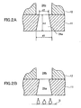
- the ejection bore 24a assumes a hollow, substantially cylindrical form and is formed such that the inside diameter of the cylinder increases toward the ejection opening; i.e., the ejection bore 24a assumes the form of a truncated cone.
- d1 is greater than d2, where d1 is the diameter of the bottom face (i.e., the ejection opening) of the cylinder and d2 is the diameter of the top face (i.e., an opening connected to the through-bore 24b located on the side of the pressurizing chamber 22) of the cylinder.
- the operation of the liquid droplet ejection apparatus 10 will be described.
- the liquid droplet ejection apparatus 10 maintains a state shown in FIG. 1B.
- the pressurizing chamber 22 and the ejection nozzle 24 are filled with liquid.
- the piezoelectric/electrostrictive element 17 attempts to contract in the X-Y plane. The force of contraction in the X-Y plane is transmitted to the upper surface of the ceramic sheet 16 on which the piezoelectric/electrostrictive element 17 is bonded.
- the ceramic sheet 16 deforms in such a manner as to decrease the volume of the pressurizing chamber 22 by ⁇ V. Accordingly, liquid contained in the pressurizing chamber 22 is pressurized and is thus ejected, in the form of a droplet, from the ejection opening of the ejection bore 24a.
- a single operation of pressurization causes simultaneous ejection of a plurality of liquid droplets for the following reason.
- pressurized liquid to be ejected is subjected to not only a force imposed along the axial direction of the cylinder (i.e., along the direction perpendicular to the ejection opening), but also a force imposed along a direction perpendicular to the axial direction of the cylinder and exerted from the inside wall surface of the hollow cylindrical ejection bore 24a; thus, the liquid becomes unlikely to assume a large granular form.
- the ratio of the diameter d0 of the liquid introduction bore 23 to the diameter d1 of the ejection opening (the diameter d1 of the bottom face of the hollow cylinder forming the ejection bore 24a) (d0/d1) must be 0.6 to 1.6.
- the ratio (d0/d1) When the ratio (d0/d1) is excessively large, during pressurization, a large amount of liquid flows back into the liquid supply path 21 from the pressurizing chamber 22 via the liquid introduction bore 23, resulting in a failure to eject liquid from the ejection opening of the ejection bore 24a.
- the present inventors studied the ratio (d0/d1) and found that a ratio (d0/d1) of 0.6-1.6 is preferred.
- the ratio of the diameter d1 of the ejection opening (the diameter d1 of the bottom face of the hollow cylinder) to the height h1 of the hollow cylinder forming the ejection bore 24a (d1/h1) must be 0.2 to 4.
- ratio (d1/h1) is less than 0.2, during ejection, contact resistance between liquid and the inside wall surface of the ejection bore 24a becomes excessively large. As a result, the force of ejection becomes insufficient, resulting in ejection defect.
- a ratio (d1/h1) of 0.2-4 is preferred.
- the rate of change (per unit time) R in the ratio of the amount of change ⁇ V in the volume of the pressurizing chamber 22 to the sum (Vn + Vk) of the volume Vn of the ejection nozzle 22 and the volume Vk of the pressurizing chamber 22, ( ⁇ V/(Vn + Vk)), must be 6 ppm/ ⁇ s to 40 ppm/ ⁇ s.
- the rate of change R represents the ejection velocity of a droplet.
- the higher the ejection velocity the greater the rate of change R
- the reason for such phenomena is, for example, as follows. Cavitation occurs within the ejection nozzle to thereby generate a bubble, which hinders stable ejection. Alternatively, after ejection, a bubble is caught in the ejection nozzle 24 (ejection bore 24a) through the ejection opening, thereby disabling next ejection.
- Table 1 shows the results of an experiment which was conducted to study ejection stability and whether or not liquid is ejected in a mistlike form, while the rate of change R was varied.
- the mark " ⁇ " appearing in the ejection stability column means that when the operation of pressurization was repeated continuously, a liquid droplet was able to be ejected in response to each operation of pressurization; and the mark "X" appearing in the ejection stability column means that a droplet was unable to be ejected in response to each operation of pressurization.
- the mark " ⁇ " appearing in the mistlike form column means that a plurality of liquid droplets were simultaneously ejected by means of a single operation of pressurization while the diameter of each liquid droplet was smaller than that of the ejection opening; and the mark "X" appearing in the mistlike form column means that ejection of liquid in a mistlike form failed.
- the expression “widened toward outlet” means the case of the first embodiment described above (i.e., the case where the inside diameter of the ejection bore 24a increases toward the ejection opening); the term “straight” means the case where the inside diameter is constant; and the expression “narrowed toward outlet” means the case where the inside diameter decreases toward the ejection opening. Liquid used in the experiment was CLENSOL having a viscosity of 0.82 mPa ⁇ S.
- a rate of change R of 6-40 ppm/ ⁇ m is preferred.
- a value obtained by dividing, by the height h1 of the hollow cylinder, the difference (d1 - d2) between the diameter d1 of the bottom face of the hollow cylinder forming the ejection bore 24a and the diameter d2 of the top face of the hollow cylinder, ((d1 - d2)/h1), must be 0.05 to 0.7.
- FIG. 3A is a plan view of a liquid droplet ejection apparatus 30 according to the second embodiment of the present invention.
- FIG. 3B is a sectional view of the liquid droplet ejection apparatus 30 taken along line 2-2 of FIG. 3A.
- the liquid droplet ejection apparatus 30 differs from the liquid droplet ejection apparatus 10 of the first embodiment merely in that a plurality of liquid-repellent layers 18 are formed on the outer side (lower side) of the ceramic sheet 11. Accordingly, this difference will be described below.
- Each liquid-repellent layer 18 is made of a fluorine-containing resin and assumes a ring-like form formed around the ejection opening of the corresponding through-bore 24a.
- the liquid-repellent layer 18 has a hollow cylindrical ejection bore formed therein, and the bottom face of the hollow cylinder forms an ejection opening.
- the through-bore 24a is called a first ejection bore 24a
- the ejection bore formed in the liquid-repellent layer 18 is called a second ejection bore 18a.
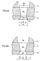
- FIGS. 4A and 4B are enlarged sectional views of the first and second ejection bores 24a and 18a.
- the first ejection bore 24a assumes a hollow, substantially cylindrical form such that the inside diameter thereof decreases toward the second ejection bore 18a.
- the second ejection bore 18a is formed such that the inside diameter thereof increases toward the ejection opening.
- d3 > d4 and d5 > d4 are established, where d3 is the diameter of the ejection opening of the second ejection bore 18a, d4 is the diameter of the opening where the first ejection bore 24a and the second ejection bore 18a are connected, and d5 is the diameter of the first ejection bore 24a as measured on the side of the through-bore 24b (pressurizing chamber 22).
- the thus-configured liquid droplet ejection apparatus 30 operates as does the liquid droplet ejection apparatus 10 described above.
- the inside diameter of the second ejection bore 18a increases toward the ejection opening.
- a single operation of pressurization induced by the piezoelectric/electrostrictive element 17 causes simultaneous ejection of a plurality of liquid droplets from the ejection opening; the diameter of the largest liquid droplet among liquid droplets ejected is not greater than the diameter d3 of the ejection opening; and the ejected liquid droplets simultaneously reach the imaginary plane S formed in such a manner as to maintain an equal distance to the ejection opening.
- a plurality of liquid droplets are simultaneously ejected by means of a single operation of pressurization for the same reason as that in the case of the liquid droplet ejection apparatus 10. Additionally, since the liquid droplet ejection apparatus 30 has the liquid-repellent layer 18 formed around the ejection opening, an ejected liquid droplet is unlikely to adhere to an area around the ejection opening. Also, since the size of the liquid-repellent layer 18 is limited, a liquid droplet adhering to the liquid-repellent layer 18 does not grow to an excessively large size. Thus, ejection of liquid is not hindered.
- This liquid droplet ejection apparatus differs from the liquid droplet ejection apparatus 10 of the first embodiment merely in that a plurality of protrusion portions for accelerating ejection of liquid in a mistlike form are formed on the inside wall of the ejection bore 24a.
- FIG. 5A is an enlarged sectional view of the ejection bore 24a
- FIG. 5B which is a sectional view of the ejection bore 24a taken along line 3-3 of FIG. 5A.
- four substantially hemispheric protrusion portions 11a each having a height t are formed on the inside wall of the ejection bore 24a. These protrusion portions 11a are circumferentially disposed in a substantially equally spaced condition while a substantially constant distance is established to the ejection opening.
- the protrusion portions 11a spit liquid while the liquid passes through the ejection bore 24a (i.e., immediately before ejection); thus, the liquid is ejected in a further mistlike form.
- the ratio of the height t of the protrusion portion to the diameter d6 of the ejection bore 24a (t/d6) is 0.03 to 0.17.
- the protrusion portion 11a is substantially hemispheric but may assume another shape so long as liquid to be ejected can be effectively split.
- the protrusion portion 11a may be formed such that a cross-sectional area thereof decreases toward the ejection opening, as in the case of FIG. 5C in which a cross section thereof is substantially triangular.
- the protrusion portion 11a may assume the form of a triangle or quadrilateral as viewed from the ejection opening (i.e., as viewed from the bottom side).
- the number of protrusion portions may be 3 as shown in FIG. 6 to 12.
- the ejection bore 24a having the protrusion portions (protrusions) 11a is formed in the ceramic sheet 11 according to the following steps.
- the diameter dp of the punch 41 is equal to the diameter d2 of the top face of the hollow cylindrical ejection bore 24a to be formed.
- the diameter D of the die 42 is greater than the diameter dp of the punch 41.
- the difference between the diameter D of the die and the diameter dp of the punch i.e., clearance between the punch 41 and the die 42 (D - dp) is not greater than 0.04 mm, preferably not greater than 0.02 mm.
- Each of the above-described liquid droplet ejection apparatuses of the present invention simultaneously eject a plurality of liquid droplets from the ejection opening by means of a single operation of pressurization effected by the piezoelectric/electrostrictive element 17 and is thus favorably applicable to, for example, a fuel injection apparatus which must inject fuel in the form of mist.
- the above-described liquid droplet apparatuses can be easily manufactured since at least the liquid supply path, the pressurizing chamber, and the ejection nozzle are integrally formed from zirconia ceramics. Also, by virtue of characteristics of zirconia ceramics, the liquid droplet ejection apparatuses exhibit high durability against frequent deformation (frequent operation of pressurization).
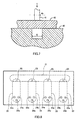
- a plurality of ejection bores 24a may be provided for a single pressurizing chamber 22.
- a common piezoelectric/electrostrictive element 17 (a single element) may be provided for a plurality of pressurizing chambers so long as liquid pressure within the pressurizing chambers can be increased.
- the first and second ejection bores 24a and 18a of the liquid droplet ejection apparatus of the second embodiment may be provided with the protrusion portions 11a of the third embodiment.
Landscapes
- Engineering & Computer Science (AREA)
- Chemical & Material Sciences (AREA)
- Combustion & Propulsion (AREA)
- Mechanical Engineering (AREA)
- General Engineering & Computer Science (AREA)
- Nozzles (AREA)
- Particle Formation And Scattering Control In Inkjet Printers (AREA)
Abstract
The liquid droplet ejection apparatus 10 includes a
liquid supply path 21, a plurality of mutually independent
pressurizing chambers 22, a plurality of liquid
introduction bores 23 for establishing communication
between the corresponding pressurizing chambers 22 and the
liquid supply path 21, and a plurality of ejection nozzles
24 for establishing communication between the corresponding
pressurizing chambers 22 and the exterior of the liquid
droplet ejection apparatus 10. An ejection bore 24a formed
at the end portion of the ejection nozzle 24 assumes a
hollow cylindrical form and is formed such that the inside
diameter thereof increases toward an ejection opening. When
a potential difference is applied between two electrodes of
the piezoelectric/electrostrictive element 17, a ceramic
sheet 16 forming the upper wall of the pressurizing chamber
22 deforms to thereby cause a change of the volume of the
pressurizing chamber. Thus, liquid pressure within the
pressurizing chamber increases to thereby cause
simultaneous ejection of a plurality of liquid droplets
from the ejection opening.
Description
- The present invention relates to a liquid droplet ejection apparatus for ejecting droplets of liquid, such as liquid material or fluid, from an ejection opening through pressurization of the liquid within a pressurizing chamber.
- The liquid droplet ejection apparatus of this type includes a pressurizing chamber into which liquid is introduced via a liquid introduction bore, an ejection nozzle communicating with the pressurizing chamber, and pressurizing means, such as a piezoelectric/electrostrictive element, for changing the volume of the pressurizing chamber. The apparatus pressurizes liquid contained in the pressurizing chamber through change in the volume of the pressurizing chamber to thereby eject the liquid in the form of droplets from an ejection opening of the ejection nozzle. Such a liquid droplet ejection apparatus is used in, for example, a color printer.
- However, since a conventional liquid droplet ejection apparatus is intended to eject merely a single droplet of liquid by a single operation of pressurization, the diameter of a liquid droplet is relatively large. Thus, the conventional apparatus cannot be used in mechanical equipment requiring mistlike fuel or the like.
- An object of the present invention is to provide a liquid droplet ejection apparatus capable of ejecting liquid in a mistlike form. The present invention provides a liquid droplet ejection apparatus comprising a pressurizing chamber communicating with a liquid supply path via a liquid introduction bore assuming a hollow cylindrical form, an ejection nozzle including an ejection bore which is connected to the pressurizing chamber and whose end portion assumes a hollow cylindrical form having a bottom face serving as an ejection opening, and a piezoelectric/electrostrictive element for changing the volume of the pressurizing chamber. The liquid droplet ejection apparatus pressurizes, by means of a change in the volume of the pressurizing chamber, liquid introduced into the pressurizing chamber via the liquid introduction bore to thereby eject the liquid in the form of liquid droplets from the circular ejection opening of the ejection bore. The liquid droplet ejection apparatus is configured such that the diameter of the largest liquid droplet among liquid droplets ejected is not greater than the diameter of the ejection opening.
- Also, the present invention provides a similar liquid droplet ejection apparatus configured such that a plurality of liquid droplets are simultaneously ejected from the ejection opening by means of a single operation of pressurization.
- Furthermore, the present invention provides a similar liquid droplet ejection apparatus configured such that a plurality of liquid droplets ejected from the ejection opening by means of a single operation of pressurization simultaneously reach an imaginary plane defined in a manner such that all points on the plane maintain an equal distance to the ejection opening.
- These liquid droplet ejection apparatuses can be used in mechanical equipment requiring mistlike fuel or the like (e.g., a gasoline-injection-type internal combustion engine) and eject (inject) liquid through effective utilization of a piezoelectric/electrostrictive element. Notably, herein (including in Claims), the expression "a hollow cylindrical form" means "a hollow, substantially cylindrical form." Accordingly, a hollow cylindrical form includes "a hollow, truncated cone."
- Preferably, any one of the liquid droplet ejection apparatuses described above is configured such that the ratio of the diameter of the liquid introduction bore to the diameter of the ejection opening is 0.6 to 1.6; the ratio of the diameter of the ejection opening to the height of the hollow cylinder forming the ejection bore located at the end portion of the ejection nozzle is 0.2 to 4; and the rate of change (per unit time) in the ratio of the amount of change in the volume of the pressurizing chamber to the sum of the volume of the ejection nozzle and the volume of the pressurizing chamber is 6 ppm/µs to 40 ppm/µs.
- The ratio of the diameter d0 of the liquid introduction bore to the diameter d1 of the ejection opening (d0/d1) is 0.6 to 1.6 for the following reason. When the ratio (d0/d1) is less than 0.6, the amount of liquid to be introduced into the pressurizing chamber via the liquid introduction bore becomes small in relation to the amount of liquid to be ejected from the ejection opening, causing an ejection defect. When the ratio (d0/d1) is in excess of 1.6, during pressurization, a large amount of liquid flows back into the liquid supply path from the pressurizing chamber via the liquid introduction bore, resulting in a failure to eject liquid from the ejection opening.
- The ratio of the diameter d1 of the ejection opening (i.e., the diameter d1 of the bottom face of the hollow cylinder) to the height h1 of the hollow cylinder forming the ejection bore located at the end portion of the ejection nozzle (d1/h1) is 0.2 to 4 for the following reason. When the ratio (d1/h1) is not greater than 4, during ejection, contact resistance between liquid and the inside wall surface of the end portion of the ejection nozzle becomes relatively large, so that vibration remaining, on liquid surface, immediately after ejection settles promptly, thereby preventing air (a bubble) from being caught in the ejection nozzle. As a result, entry of a bubble into the pressurizing chamber from the ejection nozzle can be prevented, thereby enhancing ejection stability. When the ratio (d1/h1) is less than 0.2, during ejection, contact resistance between liquid and the inside wall surface of the end portion of the ejection nozzle becomes excessively large. As a result, the force of ejection becomes insufficient, resulting in disabled ejection.
- The rate of change (per unit time) R in the ratio of the amount of change ΔV in the volume of the pressurizing chamber to the sum of the volume Vn of the ejection nozzle and the volume Vk of the pressurizing chamber (ΔV/(Vn + Vk)) is 6 ppm/µs to 40 ppm/µs for the following reason. The greater the rate of change R, the smaller liquid droplets become. However, when the rate of change R is in excess of 40 ppm/µs, ejection becomes unstable. When the rate of change R is less than 6 ppm/µs, droplets to be ejected become granular. As a result, an object that a plurality of liquid droplets are ejected by means of a single operation of pressurization cannot be attained.
- Preferably, any one of the liquid droplet ejection apparatuses described above is configured such that the inside diameter of the hollow cylinder forming the ejection bore located at the end portion of the ejection nozzle increases toward the ejection opening. In this case, preferably, a value obtained by dividing, by the height h1 of the hollow cylinder, the difference between the diameter d1 of the bottom face of the hollow cylinder forming the ejection bore located at the end portion of the ejection nozzle and the diameter d2 of the top face of the hollow cylinder serving as an opening located on the side of the pressurizing chamber ((d1 - d2)/h1) is 0.05 to 0.7.
- Through employment of the geometric features mentioned above, the liquid is ejected in a mistlike form for the following reason. Conceivably, during ejection, the liquid is subjected to not only a force imposed along the axial direction of the hollow cylinder (i.e., along the direction perpendicular to a plane serving as the ejection opening), but also a force imposed along a direction perpendicular to the axial direction and exerted from the inside wall surface of the hollow cylinder; thus, the liquid becomes unlikely to assume a large granular form.
- Also, preferably, the ejection bore located at the end portion of the ejection nozzle comprises a first ejection bore formed in a thin-plate member and assuming a hollow cylindrical form having a top face located on the side of the pressurizing chamber and a bottom face located on the side of the ejection opening; and a second ejection bore assuming a hollow cylindrical form and formed in a liquid-repellent layer formed on the surface of the thin-plate member located on the side of the ejection opening, a top face of the hollow cylinder forming an opening connected to the bottom face of the first ejection bore, a bottom face of the hollow cylinder forming the ejection opening of the ejection nozzle. The inside diameter of the second ejection bore increases toward the ejection opening.
- In this case, preferably, a value obtained by dividing, by the height h2 of the second ejection bore, the difference between the diameter d3 of the ejection opening of the second ejection bore and the diameter d4 of the opening of the second ejection bore connected to the first ejection bore ((d3 -d4)/h2) is 0.5 to 2.0.
- The liquid-repellent layer is provided in order to prevent adhesion of liquid droplets to an area around the ejection opening during ejection. When the liquid-repellent layer is provided, the liquid-repellent layer substantially serves as the end portion of the ejection nozzle. Accordingly, when, as mentioned above, the hollow cylindrical second ejection bore formed in the liquid-repellent layer is configured such that the inside diameter thereof increases toward the ejection opening, the liquid is subjected to not only a force imposed along the axial direction of the second ejection bore (hollow cylinder), but also a force imposed along a direction perpendicular to the axial direction; thus, the liquid becomes unlikely to assume a granular form. As a result, the liquid is ejected in a mistlike form.
- Further, preferably, in the above-described liquid droplet ejection apparatus having the first and second ejection bores, the inside diameter of the first ejection bore decreases toward the second ejection bore.
- Through employment of the geometric feature that the inside diameter of the first ejection bore decreases toward the second ejection bore, variation in liquid pressure within the pressurizing chamber immediately after ejection becomes unlikely to occur, thereby lowering the possibility of entry of a bubble into the pressurizing chamber from the ejection nozzle. As a result, ejection becomes stable.
- Also, preferably, in any one of the liquid droplet ejection apparatuses described above, a protrusion portion is formed on the inside wall surface of the ejection bore. In this case, preferably, the ratio of the height t of the protrusion portion to the diameter d6 of the ejection opening (t/d6) is 0.03 to 0.17. Further, preferably, the protrusion portions are formed in an amount of 3 to 12.
- The protrusion portions split a liquid droplet immediately before ejection, thereby facilitating ejection of liquid in a mistlike form.
- Preferably, in any one of the liquid droplet ejection apparatuses described above, the pressurizing chamber and the ejection nozzle are integrally formed of zirconia ceramics.
- By virtue of characteristics of zirconia ceramics, a liquid droplet ejection apparatus having high durability against frequent deformation can be readily manufactured.
- Embodiments of the present invention will next be described with reference to drawings. Herein, the term "piezoelectric/electrostrictive" means piezoelectric and/or electrostrictive. The piezoelectric/electrostrictive element is widely known as an element characterized by extending primarily in a direction parallel to an externally applied electric field and contracting in a direction perpendicular to the electric field and adapted to convert electrical energy to mechanical energy and vice versa. A piezoelectric element is characterized by exhibiting coercive electric field (external electric field as observed upon inversion of polarization) of relatively high intensity. An electrostrictive element is characterized by exhibiting coercive electric field of very low intensity.
-
- FIG. 1A is a plan view of a liquid droplet ejection apparatus according to a first embodiment of the present invention;
- FIG. 1B is a sectional view of the liquid droplet ejection apparatus taken along line 1-1 of FIG. 1A;
- FIG. 2A is an enlarged sectional view of an ejection bore of the liquid droplet ejection apparatus shown in FIG. 1B;
- FIG. 2B is a view showing a state immediately after ejection of liquid droplets from the ejection bore shown in FIG. 2A;
- FIG. 3A is a plan view of a liquid droplet ejection apparatus according to a second embodiment of the present invention;
- FIG. 3B is a sectional view of the liquid droplet ejection apparatus taken along line 2-2 of FIG. 3A;
- FIG. 4A is an enlarged sectional view of an ejection bore of the liquid droplet ejection apparatus shown in FIG. 3B;
- FIG. 4B is a view showing a state immediately after ejection of liquid droplets from the ejection bore shown in FIG. 4A;
- FIG. 5A is an enlarged sectional view of an ejection bore of a liquid droplet ejection apparatus according to a third embodiment of the present invention;
- FIG. 5B is a sectional view of the ejection bore taken along line 3-3 of FIG. 5A;
- FIG. 5C is a sectional view of an ejection bore showing another example of protrusion portions of the third embodiment;
- FIG. 6 is an enlarged sectional view of an ejection bore of a liquid droplet ejection apparatus according to a modification of the third embodiment of the present invention taken along a line similar to line 3-3 of FIG. 5A;
- FIG. 7 is a view for explaining a method for manufacturing the ejection bore of the liquid droplet ejection apparatus according to the third embodiment; and
- FIG. 8 is a plan view of a liquid droplet ejection apparatus according to another modified embodiment of the present invention.
-
- FIG. 1A is a plan view of a liquid
droplet ejection apparatus 10 according to a first embodiment of the present invention. FIG. 1B is a sectional view of the liquiddroplet ejection apparatus 10 taken along line 1-1 of FIG. 1A. The liquiddroplet ejection apparatus 10 is formed such that a plurality of ceramic thin-plate members (hereinafter called "ceramic sheets") 11-16 are sequentially stacked and press-bonded. The liquiddroplet ejection apparatus 10 includes abody 10a assuming substantially the form of a rectangular parallelepiped whose sides extend in parallel with the corresponding X, Y, and Z axes of a rectangular coordinate system, and a piezoelectric/electrostrictive element 17 bonded on an outer surface of theceramic sheet 16. - The liquid
droplet ejection apparatus 10 includes aliquid supply path 21, a plurality of mutuallyindependent pressurizing chambers 22, a plurality of liquid introduction bores 23 for establishing communication between thecorresponding pressurizing chambers 22 and theliquid supply path 21, and a plurality ofejection nozzles 24 for establishing communication between thecorresponding pressurizing chambers 22 and the exterior of the liquiddroplet ejection apparatus 10. - The
liquid supply path 21 is a space defined by the side wall surface of an oval cutout portion formed in theceramic sheet 13 and whose major and minor axes extend along the X axis and the Y axis, respectively, the upper surface of theceramic sheet 12, and the lower surface of theceramic sheet 14. Theliquid supply path 21 communicates with an unillustrated liquid source to thereby be always filled with liquid to be ejected. - The plurality of pressurizing
chambers 22 are spaces each of which is defined by the side wall surface of an oval cutout portion formed in theceramic sheet 15 and whose major and minor axes extend along the Y axis and the X axis, respectively, the upper surface of theceramic sheet 14, and the lower surface of theceramic sheet 16. An end portion of each pressurizingchamber 22 in relation to the positive direction of the Y axis extends in such a manner as to project above theliquid supply path 21, so that the pressurizingchamber 22 communicates, at the end portion, with theliquid supply path 21 through the corresponding hollow cylindrical liquid introduction bore 23 of diameter d0 formed in theceramic sheet 14. Each piezoelectric/electrostrictive element 17 is slightly smaller than the corresponding pressurizingchamber 22 as viewed from above and is bonded on the upper surface of theceramic sheet 16 in such a manner as to be disposed within the pressurizingchamber 22 as viewed from above. Each piezoelectric/electrostrictive element 17 operates according to the potential difference between unillustrated electrodes disposed on the upper and lower surfaces of the piezoelectric/electrostrictive element 17, thereby deforming the ceramic sheet 16 (upper wall of the pressurizing chamber 22) and thus changing the volume of the pressurizingchamber 22 by ΔV. - The plurality of
ejection nozzles 24 are each formed through coaxial arrangement hollow, substantially cylindrical (i.e., circular as viewed from above) through-bores 24a-24d formed in the ceramic sheets 11-14, respectively. The through-bore 24d communicates with the pressurizingchamber 22 at the lower surface of an end portion of the pressurizingchamber 22 in relation to the negative direction of the Y axis (i.e., an end portion opposite an end portion at which the liquid introduction bore 23 is located). The through-bore 24d is the largest in diameter among the through-bores 24a-24d. The diameter of the through-bore 24c is greater than that of the through-bore 24b. The diameter of the through-bore 24b is greater than that of the through-bore 24a (the maximum diameter of the through-bore 24a). The through-bore 24a serves as the end portion of the ejection nozzle (i.e., an ejection-side end portion). The bottom face of the hollow cylinder serves as an ejection opening for ejecting liquid droplets toward the exterior of the liquiddroplet ejection apparatus 10. Accordingly, hereinafter the through-bore 24a is called the ejection bore 24a. - As shown in the enlarged sectional views of FIGS. 2A and 2B, the
ejection bore 24a assumes a hollow, substantially cylindrical form and is formed such that the inside diameter of the cylinder increases toward the ejection opening; i.e., theejection bore 24a assumes the form of a truncated cone. In other words, d1 is greater than d2, where d1 is the diameter of the bottom face (i.e., the ejection opening) of the cylinder and d2 is the diameter of the top face (i.e., an opening connected to the through-bore 24b located on the side of the pressurizing chamber 22) of the cylinder. - Next, the operation of the liquid
droplet ejection apparatus 10 will be described. When no potential difference is applied between the two electrodes of the piezoelectric/electrostrictive element 17, the liquiddroplet ejection apparatus 10 maintains a state shown in FIG. 1B. At this time, the pressurizingchamber 22 and theejection nozzle 24 are filled with liquid. Next, when a potential difference is applied between the two electrodes of the piezoelectric/electrostrictive element 17, the piezoelectric/electrostrictive element 17 attempts to contract in the X-Y plane. The force of contraction in the X-Y plane is transmitted to the upper surface of theceramic sheet 16 on which the piezoelectric/electrostrictive element 17 is bonded. Thus, theceramic sheet 16 deforms in such a manner as to decrease the volume of the pressurizingchamber 22 by ΔV. Accordingly, liquid contained in the pressurizingchamber 22 is pressurized and is thus ejected, in the form of a droplet, from the ejection opening of the ejection bore 24a. - Next, when the potential difference applied to the two electrodes of the piezoelectric/
electrostrictive element 17 is canceled, the deformation of theceramic sheet 16 induced by activation of the piezoelectric/electrostrictive element 17 is undone; thus, the volume of the pressurizingchamber 22 is restored. At this time, since the pressure of liquid contained in the pressurizingchamber 22 drops, liquid contained in theliquid supply path 21 is sucked (introduced) into the pressurizingchamber 22 via the liquid introduction bore 23. The action described above is repeated to thereby continuously eject liquid droplets. - The above-described ejection of liquid droplets will be described in detail. As shown in FIG. 2B, as a result of a single operation of pressurization effected by the piezoelectric/
electrostrictive element 17, a plurality of liquid droplets are simultaneously ejected from the ejection opening. The diameter of the largest liquid droplet among the ejected liquid droplets is not greater than the diameter d1 of the ejection opening. These liquid droplets simultaneously reach an imaginary plane S formed in such a manner as to maintain an equal distance to the ejection opening. - A single operation of pressurization causes simultaneous ejection of a plurality of liquid droplets for the following reason. Conceivably, since the inside diameter of the hollow cylindrical ejection bore 24a increases toward the ejection opening, pressurized liquid to be ejected is subjected to not only a force imposed along the axial direction of the cylinder (i.e., along the direction perpendicular to the ejection opening), but also a force imposed along a direction perpendicular to the axial direction of the cylinder and exerted from the inside wall surface of the hollow cylindrical ejection bore 24a; thus, the liquid becomes unlikely to assume a large granular form.
- In this case, preferably, in order to simultaneously eject a plurality of liquid droplets by means of a single operation of pressurization, the following requirements (1)-(4) are satisfied.
- (1) The ratio of the diameter d0 of the liquid introduction bore 23 to the diameter d1 of the ejection opening (the diameter d1 of the bottom face of the hollow cylinder forming the ejection bore 24a) (d0/d1) must be 0.6 to 1.6.
- When the ratio (d0/d1) is excessively small, resistance associated with introduction of liquid from the
liquid supply path 21 to the pressurizingchamber 22 via the liquid introduction bore 23 becomes excessively large. Thus, the amount of liquid introduced into the pressurizingchamber 22 from theliquid supply path 21 becomes insufficient in relation to the amount of liquid ejected from the pressurizingchamber 22 via theejection nozzle 24. As a result, a bubble enters the pressurizingchamber 22 through theejection nozzle 24. The presence of the bubble disables ejection of a liquid droplet. When the ratio (d0/d1) is excessively large, during pressurization, a large amount of liquid flows back into theliquid supply path 21 from the pressurizingchamber 22 via the liquid introduction bore 23, resulting in a failure to eject liquid from the ejection opening of the ejection bore 24a. The present inventors studied the ratio (d0/d1) and found that a ratio (d0/d1) of 0.6-1.6 is preferred. - (2) The ratio of the diameter d1 of the ejection opening (the diameter d1 of the bottom face of the hollow cylinder) to the height h1 of the hollow cylinder forming the ejection bore 24a (d1/h1) must be 0.2 to 4.
- Immediately after ejection, liquid surface vibrates to a relatively large extent, and the vibration remains. As a result, air (a bubble) is caught in the ejection nozzle 24 (particularly, an edge portion where the ceramic sheet is bonded) and then enters the pressurizing
chamber 22, resulting in subsequent impairment in ejection stability. When the ratio (d1/h1) is not greater than 4, during ejection, contact resistance between liquid and the inside wall surface of theejection bore 24a becomes relatively large, so that vibration remaining, on the liquid surface, immediately after ejection settles promptly. Accordingly, air's (a bubble's) being caught in theejection nozzle 24 can be prevented, thereby preventing entry of a bubble into the pressurizingchamber 22 and thus enhancing ejection stability. When the ratio (d1/h1) is less than 0.2, during ejection, contact resistance between liquid and the inside wall surface of theejection bore 24a becomes excessively large. As a result, the force of ejection becomes insufficient, resulting in ejection defect.
Thus, a ratio (d1/h1) of 0.2-4 is preferred. - (3) The rate of change (per unit time) R in the ratio of the amount of change ΔV in the volume of the pressurizing
chamber 22 to the sum (Vn + Vk) of the volume Vn of theejection nozzle 22 and the volume Vk of the pressurizingchamber 22, (ΔV/(Vn + Vk)), must be 6 ppm/µs to 40 ppm/µs. - The rate of change R represents the ejection velocity of a droplet. Experiments revealed that the higher the ejection velocity (the greater the rate of change R), the smaller a liquid droplet becomes; and when the ejection velocity is excessively high (the rate of change R is in excess of 40 ppm/µs), ejection becomes unstable. The reason for such phenomena is, for example, as follows. Cavitation occurs within the ejection nozzle to thereby generate a bubble, which hinders stable ejection. Alternatively, after ejection, a bubble is caught in the ejection nozzle 24 (ejection bore 24a) through the ejection opening, thereby disabling next ejection. When the ejection velocity is excessively low (the rate of change R is less than 6 ppm/µs), a droplet to be ejected tends to become granular. As a result, a single operation of pressurization causes ejection of merely a single liquid droplet. Thus, through determination of the ejection velocity as specified above, liquid is ejected stably in a mistlike form.
- Table 1 shows the results of an experiment which was conducted to study ejection stability and whether or not liquid is ejected in a mistlike form, while the rate of change R was varied. In Table 1, the mark "○" appearing in the ejection stability column means that when the operation of pressurization was repeated continuously, a liquid droplet was able to be ejected in response to each operation of pressurization; and the mark "X" appearing in the ejection stability column means that a droplet was unable to be ejected in response to each operation of pressurization. The mark "○" appearing in the mistlike form column means that a plurality of liquid droplets were simultaneously ejected by means of a single operation of pressurization while the diameter of each liquid droplet was smaller than that of the ejection opening; and the mark "X" appearing in the mistlike form column means that ejection of liquid in a mistlike form failed. The expression "widened toward outlet" means the case of the first embodiment described above (i.e., the case where the inside diameter of the ejection bore 24a increases toward the ejection opening); the term "straight" means the case where the inside diameter is constant; and the expression "narrowed toward outlet" means the case where the inside diameter decreases toward the ejection opening. Liquid used in the experiment was CLENSOL having a viscosity of 0.82 mPa·S.

- As understood from the Table, a rate of change R of 6-40 ppm/µm is preferred.
- (4) A value obtained by dividing, by the height h1 of the hollow cylinder, the difference (d1 - d2) between the diameter d1 of the bottom face of the hollow cylinder forming the ejection bore 24a and the diameter d2 of the top face of the hollow cylinder, ((d1 - d2)/h1), must be 0.05 to 0.7.
- When the ratio ((d1 - d2)/h1) is excessively large, a force imposed on liquid along the axial direction of the hollow cylinder forming the ejection bore 24a (i.e., along the direction perpendicular to the ejection opening) becomes excessively small, resulting in impairment in ejection stability. When the ratio ((d1 - d2)/h1) is excessively small, a force imposed on the liquid along a direction perpendicular to the axial direction becomes excessively small; as a result, the ejected liquid becomes unlikely to assume a mistlike form. Thus, a ratio (d1/h1) of 0.05-0.7 is preferred.
- Next, a second embodiment of a liquid droplet ejection apparatus of the present invention will be described. FIG. 3A is a plan view of a liquid
droplet ejection apparatus 30 according to the second embodiment of the present invention. FIG. 3B is a sectional view of the liquiddroplet ejection apparatus 30 taken along line 2-2 of FIG. 3A. The liquiddroplet ejection apparatus 30 differs from the liquiddroplet ejection apparatus 10 of the first embodiment merely in that a plurality of liquid-repellent layers 18 are formed on the outer side (lower side) of theceramic sheet 11. Accordingly, this difference will be described below. - Each liquid-
repellent layer 18 is made of a fluorine-containing resin and assumes a ring-like form formed around the ejection opening of the corresponding through-bore 24a. Specifically, the liquid-repellent layer 18 has a hollow cylindrical ejection bore formed therein, and the bottom face of the hollow cylinder forms an ejection opening. In the second embodiment, the through-bore 24a is called afirst ejection bore 24a, and the ejection bore formed in the liquid-repellent layer 18 is called a second ejection bore 18a. - FIGS. 4A and 4B are enlarged sectional views of the first and second ejection bores 24a and 18a. The
first ejection bore 24a assumes a hollow, substantially cylindrical form such that the inside diameter thereof decreases toward the second ejection bore 18a. Thesecond ejection bore 18a is formed such that the inside diameter thereof increases toward the ejection opening. That is, the relationships d3 > d4 and d5 > d4 are established, where d3 is the diameter of the ejection opening of the second ejection bore 18a, d4 is the diameter of the opening where the first ejection bore 24a and thesecond ejection bore 18a are connected, and d5 is the diameter of the first ejection bore 24a as measured on the side of the through-bore 24b (pressurizing chamber 22). - The thus-configured liquid
droplet ejection apparatus 30 operates as does the liquiddroplet ejection apparatus 10 described above. As shown in FIG. 4B, the inside diameter of the second ejection bore 18a increases toward the ejection opening. Thus, a single operation of pressurization induced by the piezoelectric/electrostrictive element 17 causes simultaneous ejection of a plurality of liquid droplets from the ejection opening; the diameter of the largest liquid droplet among liquid droplets ejected is not greater than the diameter d3 of the ejection opening; and the ejected liquid droplets simultaneously reach the imaginary plane S formed in such a manner as to maintain an equal distance to the ejection opening. - A plurality of liquid droplets are simultaneously ejected by means of a single operation of pressurization for the same reason as that in the case of the liquid
droplet ejection apparatus 10. Additionally, since the liquiddroplet ejection apparatus 30 has the liquid-repellent layer 18 formed around the ejection opening, an ejected liquid droplet is unlikely to adhere to an area around the ejection opening. Also, since the size of the liquid-repellent layer 18 is limited, a liquid droplet adhering to the liquid-repellent layer 18 does not grow to an excessively large size. Thus, ejection of liquid is not hindered. Furthermore, since the inside diameter of the first ejection bore 24a decreases toward the second ejection bore 18a, variation of liquid pressure within the pressurizingchamber 22 immediately after ejection becomes unlikely to occur, thereby lowering the possibility of entry of a bubble into the pressurizingchamber 22 from theejection nozzle 24 immediately after ejection. - In this case, preferably, in order to simultaneously eject a plurality of liquid droplets, in addition to the requirements (1)-(3) described above, the following requirement (5) is satisfied.
- (5) A value obtained by dividing, by the height h2 of the second ejection bore 18a, the difference (d3 - d4) between the diameter d3 of the ejection opening of the second ejection bore 18a and the diameter d4 of the opening of the second ejection bore 18a connected to the
first ejection bore 24a, ((d3 -d4)/h2), must be 0.5 to 2.0. - When the ratio ((d3 - d4)/h2) is excessively large, a force imposed on liquid along the axial direction of the hollow cylinder forming the second ejection bore 18a (i.e., along the direction perpendicular to the ejection opening) becomes excessively small, resulting in impairment in ejection stability. When the ratio ((d3 - d4)/h2) is excessively small, a force imposed on the liquid along a direction perpendicular to the axial direction becomes excessively small; as a result, the ejected liquid becomes unlikely to assume a mistlike form. Thus, a ratio ((d3 - d4)/h2) of 0.5-2.0 is preferred.
- Next, a third embodiment of a liquid droplet ejection apparatus of the present invention will be described. This liquid droplet ejection apparatus differs from the liquid
droplet ejection apparatus 10 of the first embodiment merely in that a plurality of protrusion portions for accelerating ejection of liquid in a mistlike form are formed on the inside wall of the ejection bore 24a. - The liquid droplet ejection apparatus according to the third embodiment will next be described in detail with reference to FIG. 5A, which is an enlarged sectional view of the ejection bore 24a, and FIG. 5B, which is a sectional view of the ejection bore 24a taken along line 3-3 of FIG. 5A. Specifically, four substantially
hemispheric protrusion portions 11a each having a height t are formed on the inside wall of the ejection bore 24a. Theseprotrusion portions 11a are circumferentially disposed in a substantially equally spaced condition while a substantially constant distance is established to the ejection opening. - In the liquid droplet ejection apparatus according to the third embodiment, the
protrusion portions 11a spit liquid while the liquid passes through the ejection bore 24a (i.e., immediately before ejection); thus, the liquid is ejected in a further mistlike form. - In this case, preferably, the ratio of the height t of the protrusion portion to the diameter d6 of the ejection bore 24a (t/d6) is 0.03 to 0.17.
- The
protrusion portion 11a is substantially hemispheric but may assume another shape so long as liquid to be ejected can be effectively split. For example, theprotrusion portion 11a may be formed such that a cross-sectional area thereof decreases toward the ejection opening, as in the case of FIG. 5C in which a cross section thereof is substantially triangular. Also, theprotrusion portion 11a may assume the form of a triangle or quadrilateral as viewed from the ejection opening (i.e., as viewed from the bottom side). The number of protrusion portions may be 3 as shown in FIG. 6 to 12. - Preferably, the ejection bore 24a having the protrusion portions (protrusions) 11a is formed in the
ceramic sheet 11 according to the following steps. - 1: A ceramic green sheet is formed by use of zirconia powder having a grain size of 0.1 to several µm; and
- 2: As shown in FIG. 7, the ceramic green sheet 40
(which will become the
ceramic sheet 11 later) is subjected to punching by use of apunch 41 and adie 42, to thereby form the ejection bore 24a. -
- The diameter dp of the
punch 41 is equal to the diameter d2 of the top face of the hollow cylindrical ejection bore 24a to be formed. The diameter D of the die 42 is greater than the diameter dp of thepunch 41. The difference between the diameter D of the die and the diameter dp of the punch (i.e., clearance between thepunch 41 and the die 42) (D - dp) is not greater than 0.04 mm, preferably not greater than 0.02 mm. - Each of the above-described liquid droplet ejection apparatuses of the present invention simultaneously eject a plurality of liquid droplets from the ejection opening by means of a single operation of pressurization effected by the piezoelectric/
electrostrictive element 17 and is thus favorably applicable to, for example, a fuel injection apparatus which must inject fuel in the form of mist. The above-described liquid droplet apparatuses can be easily manufactured since at least the liquid supply path, the pressurizing chamber, and the ejection nozzle are integrally formed from zirconia ceramics. Also, by virtue of characteristics of zirconia ceramics, the liquid droplet ejection apparatuses exhibit high durability against frequent deformation (frequent operation of pressurization). - While the present invention has been described with reference to the embodiments described above, it will be apparent to those skilled in the art that the present invention is not limited thereto, but may be modified in various forms within the scope of the present invention. For example, as in the case of a liquid droplet ejection apparatus whose plan view is shown in FIG. 8, a plurality of ejection bores 24a may be provided for a
single pressurizing chamber 22. Also, a common piezoelectric/electrostrictive element 17 (a single element) may be provided for a plurality of pressurizing chambers so long as liquid pressure within the pressurizing chambers can be increased. Furthermore, the first and second ejection bores 24a and 18a of the liquid droplet ejection apparatus of the second embodiment may be provided with theprotrusion portions 11a of the third embodiment.
Claims (14)
- A liquid droplet ejection apparatus comprising a pressurizing chamber communicating with a liquid supply path via a liquid introduction bore assuming a hollow cylindrical form, an ejection nozzle including an ejection bore which is connected to said pressurizing chamber and whose end portion assumes a hollow cylindrical form having a bottom face serving as an ejection opening, and a piezoelectric/electrostrictive element for changing a volume of said pressurizing chamber, said liquid droplet ejection apparatus pressurizing, by means of a change in said volume, liquid introduced into said pressurizing chamber via said liquid introduction bore to thereby eject said liquid in a form of liquid droplets from said circular ejection opening of said ejection bore, said liquid droplet ejection apparatus being configured such that a diameter of a largest liquid droplet among said liquid droplets ejected is not greater than a diameter of said ejection opening.
- A liquid droplet ejection apparatus comprising a pressurizing chamber communicating with a liquid supply path via a liquid introduction bore assuming a hollow cylindrical form, an ejection nozzle including an ejection bore which is connected to said pressurizing chamber and whose end portion assumes a hollow cylindrical form having a bottom face serving as an ejection opening, and a piezoelectric/electrostrictive element for changing a volume of said pressurizing chamber, said liquid droplet ejection apparatus pressurizing, by means of a change in said volume, liquid introduced into said pressurizing chamber via said liquid introduction bore to thereby eject said liquid in a form of a liquid droplet from said ejection opening of said ejection bore, said liquid droplet ejection apparatus being configured such that a plurality of liquid droplets are simultaneously ejected from said ejection opening by means of a single operation of pressurization.
- A liquid droplet ejection apparatus comprising a pressurizing chamber communicating with a liquid supply path via a liquid introduction bore assuming a hollow cylindrical form, an ejection nozzle including an ejection bore which is connected to said pressurizing chamber and whose end portion assumes a hollow cylindrical form having a bottom face serving as an ejection opening, and a piezoelectric/electrostrictive element for changing a volume of said pressurizing chamber, said liquid droplet ejection apparatus pressurizing, by means of a change in said volume, liquid introduced into said pressurizing chamber via said liquid introduction bore to thereby eject said liquid in a form of a liquid droplet from said ejection opening of said ejection bore, said liquid droplet ejection apparatus being configured such that a plurality of liquid droplets ejected from said ejection opening by means of a single operation of pressurization simultaneously reaches an imaginary plane defined in a manner such that all points on the plane maintain an equal distance to said ejection opening.
- A liquid droplet ejection apparatus as described in any one of Claims 1 to 3, wherein a ratio of a diameter of said liquid introduction bore to a diameter of said ejection opening is 0.6 to 1.6;a ratio of the diameter of said ejection opening to a height of said hollow cylinder forming said ejection bore located at an end portion of said ejection nozzle is 0.2 to 4; anda rate of change per unit time in a ratio of an amount of change in a volume of said pressurizing chamber to a sum of a volume of said ejection nozzle and the volume of said pressurizing chamber is 6 ppm/µs to 40 ppm/µs.
- A liquid droplet ejection apparatus as described in any one of Claims 1 to 4, wherein an inside diameter of said hollow cylinder forming said ejection bore located at an end portion of said ejection nozzle increases toward said ejection opening.
- A liquid droplet ejection apparatus as described in any one of Claims 1 to 5, wherein a value obtained by dividing, by the height of said hollow cylinder, a difference between a diameter of said bottom face of said hollow cylinder forming said ejection bore located at an end portion of said ejection nozzle and a diameter of a top face of said hollow cylinder serving as an opening located on a side of said pressurizing chamber is 0.05 to 0.7.
- A liquid droplet ejection apparatus as described in any one of Claims 1 to 4, wherein said ejection bore located at an end portion of said ejection nozzle comprises:a first ejection bore formed in a thin-plate member and assuming a hollow cylindrical form having a top face located on a side of said pressurizing chamber and a bottom face located on a side of said ejection opening; anda second ejection bore assuming a hollow cylindrical form and formed in a liquid-repellent layer formed on a surface of said thin-plate member located on a side of said ejection opening, a top face of said hollow cylinder forming an opening connected to said bottom face of said first ejection bore, a bottom face of said hollow cylinder forming said ejection opening of said ejection nozzle;an inside diameter of said second ejection bore increasing toward said ejection opening.
- A liquid droplet ejection apparatus as described in Claim 7, wherein a value obtained by dividing, by a height of said second ejection bore, a difference between a diameter of said ejection opening of said second ejection bore and a diameter of said opening of said second ejection bore connected to said first ejection bore is 0.5 to 2.0.
- A liquid droplet ejection apparatus as described in Claim 7 or 8, wherein an inside diameter of said first ejection bore decreases toward said second ejection bore.
- A liquid droplet ejection apparatus as described in any one of Claims 1 to 9, wherein a protrusion portion is formed on an inside wall surface of said ejection bore.
- A liquid droplet ejection apparatus as described in Claim 10, wherein a ratio of a height of said protrusion portion to a diameter of said ejection opening is 0.03 to 0.17.
- A liquid droplet ejection apparatus as described in Claim 10 or 11, wherein said projections are formed in an amount of 3 to 12.
- A liquid droplet ejection apparatus as described in any one of Claims 1 to 12, wherein said pressurizing chamber and said ejection nozzle are integrally formed of zirconia ceramics.
- A method for ejecting liquid droplets by use of a liquid droplet ejection apparatus comprising a pressurizing chamber communicating with a liquid supply path via a liquid introduction bore assuming a hollow, substantially cylindrical form, an ejection nozzle connected to said pressurizing chamber, an end portion of said ejection nozzle, located on an ejection side opposite said pressurizing chamber, assuming a substantially hollow, cylindrical form, a bottom face of said hollow cylinder forming a circular ejection opening, and a piezoelectric/electrostrictive element for changing a volume of said pressurizing chamber, said liquid droplet ejection apparatus being configured such that a ratio of a diameter of said liquid introduction bore to a diameter of said ejection opening is 0.6 to 1.6 and such that a ratio of the diameter of said ejection opening to a height of said hollow cylinder of said end portion located on the ejection side is 0.2 to 4, said method being adapted to eject liquid from said ejection opening and comprising a step of:actuating said piezoelectric/electrostrictive element so as to attain a rate of change per unit time in a ratio of an amount of change in a volume of said pressurizing chamber to a sum of a volume of said ejection nozzle and the volume of said pressurizing chamber of 6 ppm/µs to 40 ppm/µs, to thereby pressurize said liquid introduced into said pressurizing chamber from said liquid supply path via said liquid introduction bore and simultaneously eject a plurality of droplets of said liquid through said ejection opening of said ejection nozzle.
Applications Claiming Priority (3)
| Application Number | Priority Date | Filing Date | Title |
|---|---|---|---|
| JP2000185494 | 2000-06-20 | ||
| JP2000185494 | 2000-06-20 | ||
| PCT/JP2001/005214 WO2001097977A1 (en) | 2000-06-20 | 2001-06-19 | Liquid droplet ejecting device and liquid droplet ejecting method |
Publications (1)
| Publication Number | Publication Date |
|---|---|
| EP1293257A1 true EP1293257A1 (en) | 2003-03-19 |
Family
ID=18685808
Family Applications (2)
| Application Number | Title | Priority Date | Filing Date |
|---|---|---|---|
| EP01305130A Withdrawn EP1166887A2 (en) | 2000-06-20 | 2001-06-13 | Liquid drop discharge device |
| EP01941088A Withdrawn EP1293257A1 (en) | 2000-06-20 | 2001-06-19 | Liquid droplet ejecting device and liquid droplet ejecting method |
Family Applications Before (1)
| Application Number | Title | Priority Date | Filing Date |
|---|---|---|---|
| EP01305130A Withdrawn EP1166887A2 (en) | 2000-06-20 | 2001-06-13 | Liquid drop discharge device |
Country Status (3)
| Country | Link |
|---|---|
| US (3) | US6474566B1 (en) |
| EP (2) | EP1166887A2 (en) |
| WO (1) | WO2001097977A1 (en) |
Cited By (2)
| Publication number | Priority date | Publication date | Assignee | Title |
|---|---|---|---|---|
| WO2007074385A3 (en) * | 2005-12-28 | 2007-10-04 | Toyota Motor Co Ltd | Fuel injection device having an orifice plate |
| WO2012168181A1 (en) * | 2011-06-08 | 2012-12-13 | Pari Pharma Gmbh | Aerosol generator |
Families Citing this family (45)
| Publication number | Priority date | Publication date | Assignee | Title |
|---|---|---|---|---|
| US6875402B2 (en) * | 2000-10-16 | 2005-04-05 | Ngk Insulators, Ltd. | Micropipette, dispenser and method for producing biochip |
| DE10065855A1 (en) * | 2000-12-22 | 2002-07-04 | Bsh Bosch Siemens Hausgeraete | Dosing device for conveying small quantities of substances |
| US7160512B2 (en) | 2001-05-01 | 2007-01-09 | Ngk Insulators, Ltd. | Method for manufacturing biochips |
| US20030116641A1 (en) * | 2001-10-02 | 2003-06-26 | Ngk Insulators, Ltd. | Liquid injection apparatus |
| JP2003214302A (en) * | 2001-11-16 | 2003-07-30 | Ngk Insulators Ltd | Liquid fuel injection device |
| JP2004052619A (en) * | 2002-07-18 | 2004-02-19 | Ngk Insulators Ltd | Liquid injection device |
| US6764023B2 (en) * | 2002-10-09 | 2004-07-20 | Industrial Technology Research Institute | Bi-direction pumping droplet mist ejection apparatus |
| EP1468748A1 (en) * | 2003-04-15 | 2004-10-20 | Microflow Engineering SA | Low-cost liquid droplet spray device and nozzle body |
| DE10329731A1 (en) * | 2003-07-02 | 2005-02-03 | Robert Bosch Gmbh | Fuel injection valve and a method for producing the same |
| JP2005074767A (en) * | 2003-08-29 | 2005-03-24 | Matsushita Electric Ind Co Ltd | Inkjet recording device |
| US7357482B2 (en) * | 2004-03-31 | 2008-04-15 | Brother Kogyo Kabushiki Kaisha | Liquid droplet-ejecting apparatus, ink-jet printer, and liquid droplet-moving apparatus |
| US20050268845A1 (en) * | 2004-06-03 | 2005-12-08 | Nordson Corporation | Apparatus and nozzle plate for dispensing liquid material |
| US20050271806A1 (en) * | 2004-06-03 | 2005-12-08 | Nordson Corporation | Dispenser and method for non-contact dispensing of adhesive |
| DE102004049280A1 (en) * | 2004-10-09 | 2006-04-13 | Robert Bosch Gmbh | Fuel injector |
| JP4902971B2 (en) * | 2005-06-27 | 2012-03-21 | 富士フイルム株式会社 | Liquid discharge head |
| WO2007016175A1 (en) * | 2005-07-28 | 2007-02-08 | Guasch Michael N | Fuel repellent compositions, fabrics and articles |
| TWI265095B (en) * | 2005-08-16 | 2006-11-01 | Ind Tech Res Inst | Nozzle plate |
| TWI294789B (en) * | 2005-11-29 | 2008-03-21 | Ind Tech Res Inst | Droplet ejecting head |
| TWI290485B (en) * | 2005-12-30 | 2007-12-01 | Ind Tech Res Inst | Spraying device |
| US7712680B2 (en) * | 2006-01-30 | 2010-05-11 | Sono-Tek Corporation | Ultrasonic atomizing nozzle and method |
| US8171973B2 (en) * | 2008-01-29 | 2012-05-08 | Nordson Corporation | Nozzle and related apparatus and method for dispensing molten thermoplastic material |
| JP2009207650A (en) * | 2008-03-04 | 2009-09-17 | Panasonic Corp | Electric power device, electronic device using the same, and power supply element inspection facility |
| US9272297B2 (en) * | 2008-03-04 | 2016-03-01 | Sono-Tek Corporation | Ultrasonic atomizing nozzle methods for the food industry |
| US8210674B2 (en) * | 2008-03-31 | 2012-07-03 | Brother Kogyo Kabushiki Kaisha | Liquid droplet jetting apparatus |
| JP5339842B2 (en) * | 2008-10-06 | 2013-11-13 | キヤノン株式会社 | Discharge head and droplet discharge device |
| KR20100114335A (en) * | 2009-04-15 | 2010-10-25 | 삼성전기주식회사 | Inkjet head |
| JP5343869B2 (en) * | 2010-01-15 | 2013-11-13 | セイコーエプソン株式会社 | Gel production equipment |
| US8876255B2 (en) * | 2012-07-31 | 2014-11-04 | Hewlett-Packard Development Company, L.P. | Orifice structure for fluid ejection device and method of forming same |
| US10066114B2 (en) | 2012-09-14 | 2018-09-04 | The Procter & Gamble Company | Ink jet delivery system comprising an improved perfume mixture |
| JP6271905B2 (en) * | 2013-08-07 | 2018-01-31 | キヤノン株式会社 | Liquid discharge head, liquid discharge apparatus, and method of manufacturing liquid discharge head |
| JP5934161B2 (en) * | 2013-09-09 | 2016-06-15 | 武蔵エンジニアリング株式会社 | Nozzle and liquid material discharge apparatus including the nozzle |
| US9433696B2 (en) | 2014-06-20 | 2016-09-06 | The Procter & Gamble Company | Microfluidic delivery system for releasing fluid compositions |
| US10076585B2 (en) | 2014-06-20 | 2018-09-18 | The Procter & Gamble Company | Method of delivering a dose of a fluid composition from a microfluidic delivery cartridge |
| US9211980B1 (en) | 2014-06-20 | 2015-12-15 | The Procter & Gamble Company | Microfluidic delivery system for releasing fluid compositions |
| US9808812B2 (en) | 2014-06-20 | 2017-11-07 | The Procter & Gamble Company | Microfluidic delivery system |
| US9744549B2 (en) * | 2015-03-16 | 2017-08-29 | The Procter & Gamble Company | System and method for dispensing material |
| US10780192B2 (en) | 2015-09-16 | 2020-09-22 | The Procter & Gamble Company | Microfluidic delivery cartridges and methods of connecting cartridges with microfluidic delivery systems |
| JP6707849B2 (en) * | 2015-12-09 | 2020-06-10 | セイコーエプソン株式会社 | Inkjet recording method |
| CN109073515B (en) * | 2016-03-31 | 2021-04-06 | 惠普发展公司,有限责任合伙企业 | Monolithic carrier structure including fluid routing for digital distribution |
| US10149917B2 (en) | 2016-11-22 | 2018-12-11 | The Procter & Gamble Company | Fluid composition and a microfluidic delivery cartridge comprising the same |
| US11305301B2 (en) | 2017-04-10 | 2022-04-19 | The Procter & Gamble Company | Microfluidic delivery device for dispensing and redirecting a fluid composition in the air |
| US12103020B2 (en) | 2017-04-10 | 2024-10-01 | The Procter & Gamble Company | Microfluidic delivery device and method for dispensing a fluid composition upward into the air |
| US11691162B2 (en) | 2017-04-10 | 2023-07-04 | The Procter & Gamble Company | Microfluidic delivery cartridge for use with a microfluidic delivery device |
| JP2019100208A (en) * | 2017-11-29 | 2019-06-24 | 株式会社デンソー | Fuel injection valve |
| US10806816B2 (en) | 2018-05-15 | 2020-10-20 | The Procter & Gamble Company | Microfluidic cartridge and microfluidic delivery device comprising the same |
Family Cites Families (23)
| Publication number | Priority date | Publication date | Assignee | Title |
|---|---|---|---|---|
| GB1552419A (en) * | 1975-08-20 | 1979-09-12 | Plessey Co Ltd | Fuel injection system |
| JPS5490416A (en) | 1977-12-27 | 1979-07-18 | Mikuni Kogyo Co Ltd | Method of supplying fuel to internal combustion engine |
| JPS6022065A (en) | 1983-07-19 | 1985-02-04 | Hitachi Metals Ltd | Fuel injector |
| JPS6111451A (en) | 1984-06-26 | 1986-01-18 | Mitsubishi Motors Corp | Fuel injection device |
| GB2203994B (en) * | 1987-03-31 | 1991-12-11 | Canon Kk | Liquid injection recording apparatus and liquid-repellent process method used for the apparatus |
| US4907748A (en) * | 1988-08-12 | 1990-03-13 | Ford Motor Company | Fuel injector with silicon nozzle |
| US5152456A (en) * | 1989-12-12 | 1992-10-06 | Bespak, Plc | Dispensing apparatus having a perforate outlet member and a vibrating device |
| JPH0424657A (en) | 1990-05-18 | 1992-01-28 | Mita Ind Co Ltd | Image forming device |
| JPH0424657U (en) * | 1990-06-22 | 1992-02-27 | ||
| JPH04134176A (en) | 1990-09-26 | 1992-05-08 | Mazda Motor Corp | Fuel injecting device for engine |
| EP0494693B1 (en) * | 1991-01-11 | 1998-04-01 | Canon Kabushiki Kaisha | Ink jet recording apparatus |
| JP3278186B2 (en) * | 1991-03-08 | 2002-04-30 | キヤノン株式会社 | Inkjet recording head |
| US5248087A (en) * | 1992-05-08 | 1993-09-28 | Dressler John L | Liquid droplet generator |
| JPH0655739A (en) * | 1992-08-03 | 1994-03-01 | Seiko Epson Corp | Inkjet recording head |
| JPH06297719A (en) * | 1993-04-16 | 1994-10-25 | Brother Ind Ltd | Liquid droplet jet device and production thereof |
| GB9412669D0 (en) * | 1994-06-23 | 1994-08-10 | The Technology Partnership Plc | Liquid spray apparatus |
| US5437255A (en) | 1994-03-15 | 1995-08-01 | Sadley; Mark L. | Fuel injection sytem employing solid-state injectors for liquid fueled combustion engines |
| US5840062A (en) | 1995-11-08 | 1998-11-24 | Gumaste; Anand V. | Solid state fluid delivery system |
| US5713333A (en) * | 1996-10-21 | 1998-02-03 | Cummins Engine Company, Inc. | Wear-resistant fuel distributor rotor |
| JP3570895B2 (en) * | 1998-07-02 | 2004-09-29 | 日本碍子株式会社 | Discharge device for raw materials and fuel |
| JP3352949B2 (en) * | 1998-07-03 | 2002-12-03 | 日本碍子株式会社 | Material / fuel discharge device |
| JP2000052552A (en) * | 1998-08-07 | 2000-02-22 | Olympus Optical Co Ltd | Droplet ejector |
| JP2001024248A (en) * | 1999-07-07 | 2001-01-26 | Samsung Electro Mech Co Ltd | Method of manufacturing multilayer piezoelectric / electrostrictive ceramic actuator by low-temperature firing method and multilayer piezoelectric / electrostrictive ceramic actuator manufactured by the method |
-
2000
- 2000-06-28 US US09/606,380 patent/US6474566B1/en not_active Expired - Fee Related
-
2001
- 2001-06-13 EP EP01305130A patent/EP1166887A2/en not_active Withdrawn
- 2001-06-19 EP EP01941088A patent/EP1293257A1/en not_active Withdrawn
- 2001-06-19 US US09/884,457 patent/US6752326B2/en not_active Expired - Fee Related
- 2001-06-19 WO PCT/JP2001/005214 patent/WO2001097977A1/en not_active Ceased
-
2004
- 2004-02-05 US US10/772,825 patent/US20040173693A1/en not_active Abandoned
Non-Patent Citations (1)
| Title |
|---|
| See references of WO0197977A1 * |
Cited By (7)
| Publication number | Priority date | Publication date | Assignee | Title |
|---|---|---|---|---|
| WO2007074385A3 (en) * | 2005-12-28 | 2007-10-04 | Toyota Motor Co Ltd | Fuel injection device having an orifice plate |
| WO2012168181A1 (en) * | 2011-06-08 | 2012-12-13 | Pari Pharma Gmbh | Aerosol generator |
| US9975136B2 (en) | 2011-06-08 | 2018-05-22 | Pari Pharma Gmbh | Aerosol generator |
| US11154896B2 (en) | 2011-06-08 | 2021-10-26 | Pari Pharma Gmbh | Aerosol generator |
| US11707758B2 (en) | 2011-06-08 | 2023-07-25 | Pari Pharma Gmbh | Aerosol generator |
| EP4230243A1 (en) * | 2011-06-08 | 2023-08-23 | PARI Pharma GmbH | Aerosol generator |
| EP4230243B1 (en) | 2011-06-08 | 2025-10-01 | PARI Pharma GmbH | Method of manufacturing a vibratable membrane for use in an aerosol generator |
Also Published As
| Publication number | Publication date |
|---|---|
| EP1166887A2 (en) | 2002-01-02 |
| WO2001097977A1 (en) | 2001-12-27 |
| US6474566B1 (en) | 2002-11-05 |
| US6752326B2 (en) | 2004-06-22 |
| US20020050533A1 (en) | 2002-05-02 |
| US20040173693A1 (en) | 2004-09-09 |
Similar Documents
| Publication | Publication Date | Title |
|---|---|---|
| US6752326B2 (en) | Liquid droplet ejection apparatus and liquid droplet ejecting method | |
| EP0732208B1 (en) | Ink jet print head having ceramic ink pump member and metallic nozzle member bonded thereto | |
| US7909438B2 (en) | Piezo-electric type inkjet printhead | |
| US7387372B2 (en) | Liquid delivery apparatus | |
| DE69936122T2 (en) | ELECTROSTATIC ACTUATOR, METHOD FOR THE PRODUCTION THEREOF, AND THIS USING LIQUID SPRAYING DEVICE | |
| EP1093857A1 (en) | Discharging device for material and fuel | |
| JPH0985946A (en) | Ink jet head and method of manufacturing the same | |
| EP0670218B1 (en) | Ink jet head | |
| EP1815991A2 (en) | Piezoelectric inkjet printhead | |
| JPWO1998022288A1 (en) | Inkjet recording head | |
| US20090195606A1 (en) | Liquid ejecting head and liquid ejecting apparatus having same | |
| US20050069429A1 (en) | Liquid delivering device | |
| US6010209A (en) | Passage forming substrate for an ink-jet recording head | |
| US20030112319A1 (en) | Low voltage ink jet printing module | |
| US8573744B2 (en) | Continuous type liquid ejection head and liquid ejection device | |
| US7866805B2 (en) | Introducing liquid for ink jet head, ink jet head, and ink jet recording apparatus | |
| US7252371B2 (en) | Liquid delivering device | |
| US20030231231A1 (en) | Fluid ejection device with drop volume modulation capabilities | |
| CN1386637A (en) | Ink-jet print head structure capable of keeping ink-jet performance constant | |
| CN115817013B (en) | Flow path components and liquid injection head | |
| JP4379128B2 (en) | Inkjet head | |
| US7600317B2 (en) | Manufacturing method of ink-jet head | |
| DE19938055A1 (en) | Actuator member for a micro-atomizer and method for its production | |
| CN101020387A (en) | Ink jet print head and method for removing bubble therein | |
| JP5091551B2 (en) | Liquid discharge head |
Legal Events
| Date | Code | Title | Description |
|---|---|---|---|
| PUAI | Public reference made under article 153(3) epc to a published international application that has entered the european phase |
Free format text: ORIGINAL CODE: 0009012 |
|
| 17P | Request for examination filed |
Effective date: 20020402 |
|
| AK | Designated contracting states |
Designated state(s): AT BE CH CY DE DK ES FI FR GB GR IE IT LI LU MC NL PT SE TR Kind code of ref document: A1 Designated state(s): AT BE CH CY DE DK ES FI FR GB GR IE IT LI LU MC NL PT SE TR |
|
| RBV | Designated contracting states (corrected) |
Designated state(s): DE FR GB IT SE |
|
| STAA | Information on the status of an ep patent application or granted ep patent |
Free format text: STATUS: THE APPLICATION HAS BEEN WITHDRAWN |
|
| 18W | Application withdrawn |
Effective date: 20050131 |