EP1292762B1 - Device for controlling the phase angle between a first and a second crankshaft - Google Patents
Device for controlling the phase angle between a first and a second crankshaft Download PDFInfo
- Publication number
- EP1292762B1 EP1292762B1 EP01937105A EP01937105A EP1292762B1 EP 1292762 B1 EP1292762 B1 EP 1292762B1 EP 01937105 A EP01937105 A EP 01937105A EP 01937105 A EP01937105 A EP 01937105A EP 1292762 B1 EP1292762 B1 EP 1292762B1
- Authority
- EP
- European Patent Office
- Prior art keywords
- crankshaft
- extension
- piston
- phase angle
- crankshafts
- Prior art date
- Legal status (The legal status is an assumption and is not a legal conclusion. Google has not performed a legal analysis and makes no representation as to the accuracy of the status listed.)
- Expired - Lifetime
Links
- 238000002485 combustion reaction Methods 0.000 claims abstract description 16
- 230000005540 biological transmission Effects 0.000 claims abstract description 6
- 238000006073 displacement reaction Methods 0.000 claims description 12
- 230000010363 phase shift Effects 0.000 claims description 7
- 230000001105 regulatory effect Effects 0.000 abstract description 2
- 238000000034 method Methods 0.000 abstract 1
- 230000006835 compression Effects 0.000 description 10
- 238000007906 compression Methods 0.000 description 10
- 239000000446 fuel Substances 0.000 description 6
- 230000001276 controlling effect Effects 0.000 description 4
- 238000007789 sealing Methods 0.000 description 4
- 239000000203 mixture Substances 0.000 description 3
- PXHVJJICTQNCMI-UHFFFAOYSA-N Nickel Chemical compound [Ni] PXHVJJICTQNCMI-UHFFFAOYSA-N 0.000 description 2
- 238000000576 coating method Methods 0.000 description 2
- 230000008878 coupling Effects 0.000 description 2
- 238000010168 coupling process Methods 0.000 description 2
- 238000005859 coupling reaction Methods 0.000 description 2
- 238000004519 manufacturing process Methods 0.000 description 2
- JVTSHOJDBRTPHD-UHFFFAOYSA-N 2,2,2-trifluoroacetaldehyde Chemical compound FC(F)(F)C=O JVTSHOJDBRTPHD-UHFFFAOYSA-N 0.000 description 1
- 229910000831 Steel Inorganic materials 0.000 description 1
- 239000011248 coating agent Substances 0.000 description 1
- 238000005516 engineering process Methods 0.000 description 1
- 230000002349 favourable effect Effects 0.000 description 1
- 238000000465 moulding Methods 0.000 description 1
- 229910052759 nickel Inorganic materials 0.000 description 1
- TVMXDCGIABBOFY-UHFFFAOYSA-N octane Chemical compound CCCCCCCC TVMXDCGIABBOFY-UHFFFAOYSA-N 0.000 description 1
- 239000010959 steel Substances 0.000 description 1
Images

Classifications
-
- F—MECHANICAL ENGINEERING; LIGHTING; HEATING; WEAPONS; BLASTING
- F16—ENGINEERING ELEMENTS AND UNITS; GENERAL MEASURES FOR PRODUCING AND MAINTAINING EFFECTIVE FUNCTIONING OF MACHINES OR INSTALLATIONS; THERMAL INSULATION IN GENERAL
- F16C—SHAFTS; FLEXIBLE SHAFTS; ELEMENTS OR CRANKSHAFT MECHANISMS; ROTARY BODIES OTHER THAN GEARING ELEMENTS; BEARINGS
- F16C3/00—Shafts; Axles; Cranks; Eccentrics
- F16C3/04—Crankshafts, eccentric-shafts; Cranks, eccentrics
- F16C3/06—Crankshafts
-
- F—MECHANICAL ENGINEERING; LIGHTING; HEATING; WEAPONS; BLASTING
- F02—COMBUSTION ENGINES; HOT-GAS OR COMBUSTION-PRODUCT ENGINE PLANTS
- F02D—CONTROLLING COMBUSTION ENGINES
- F02D15/00—Varying compression ratio
- F02D15/04—Varying compression ratio by alteration of volume of compression space without changing piston stroke
-
- F—MECHANICAL ENGINEERING; LIGHTING; HEATING; WEAPONS; BLASTING
- F16—ENGINEERING ELEMENTS AND UNITS; GENERAL MEASURES FOR PRODUCING AND MAINTAINING EFFECTIVE FUNCTIONING OF MACHINES OR INSTALLATIONS; THERMAL INSULATION IN GENERAL
- F16D—COUPLINGS FOR TRANSMITTING ROTATION; CLUTCHES; BRAKES
- F16D3/00—Yielding couplings, i.e. with means permitting movement between the connected parts during the drive
- F16D3/02—Yielding couplings, i.e. with means permitting movement between the connected parts during the drive adapted to specific functions
- F16D3/10—Couplings with means for varying the angular relationship of two coaxial shafts during motion
Definitions
- the present invention relates to a device for controlling the phase angle between a first and a second crankshaft of an internal combustion engine, said internal combustion engine comprising at least one primary cylinder which communicates with at least one secondary cylinder, a primary piston being movably arranged in each primary cylinder, said primary piston being connected to the first crankshaft, and in every secondary cylinder there being movably arranged a secondary piston which is connected to the second crankshaft, with said first and second crankshafts being connected to each other by means of a transmission, and with the device comprising means for obtaining the phase shift control and a crankshaft extension intended for said phase angle control which is connected fixed against rotation to one of said crankshafts, and rotationally connected to the second of said crankshafts, according to the preamble of appended claim 1.
- a fuel air mixture is compressed in a combustion chamber, where it is ignited and burnt when the piston is in its uppermost position.
- the compression of said fuel air mixture is determined by the compression ratio of the engine in question, defined as the ration between the volume in the cylinder when the piston is in its lowest and uppermost positions.
- Modern otto engines usually have a compression ration around 10:1 (compression figure 10), while supercharged engines, for example turbo engines, have a lower and diesel engines a considerably much higher compression ratio.
- the compression ratio of the engine affects the combustion of the fuel air mixture.
- a high compression contributes to an effective combustion, which in turn contributes to a high efficiency and low fuel consumption.
- a need for a high octane fuel particularly in the case of high engine loads, in order to avoid uncontrolled combustion.
- US 5;638,777 describes an internal combustion, engine with a variable compression ratio.
- the engine has a number of primary cylinders, a corresponding number of secondary cylinders which each communicates with a corresponding primary cylinder.
- a primary piston connected to a first crankshaft, said primary piston being arranged to carry out a movement back and forth, and in a corresponding way there is in every secondary cylinder a secondary piston connected to a second crankshaft said secondary piston being arranged to carry out a movement back and forth.
- a gear wheel transmission and a device for phase angle shift between the shafts there is arranged between said first and second crankshafts, with the purpose of obtaining a compression ratio which depends on the current load of the engine.
- Said device comprises a driving shaft fixedly connected to said second crankshaft, equipped with spiral-shaped splines concentrically arranged inside an outer casing.
- the outer casing exhibits a first gear wheel intended to interact with a second gear wheel arranged on said first crankshaft, and internal spiral-shaped splines.
- a displaceable pipe element Between the outer casing and the drive shaft there is arranged a displaceable pipe element, the enveloping surface of which is equipped with spiral-shaped splines intended to cooperate with said internal spiral-shaped splines of the outer casing.
- the pipe element is, in addition, equipped with internal spiral-shaped splines which cooperate with said spiral-shaped splines arranged on the drive shaft.
- a phase angle shift is obtained between said first gear wheels and said drive shaft, and thus also between the first and second crankshafts.
- the object of the present invention is to create the possibility to achieve a device for controlling the phase angle between a first and a second crankshaft of an internal combustion engine, which, relative to previous technology is more cost-efficient to manufacture.
- the device according to the invention is, as mentioned previously, arranged between a first and a second crankshaft of an internal combustion engine which comprises at least one primary cylinder which communicates with at least one secondary cylinder, with a primary piston being movably arranged in each primary cylinder, said primary piston being connected to the first crankshaft, and in every secondary cylinder there is movably arranged a secondary piston which is connected to the second crankshaft, with said first and second crankshafts being connected to each other by means of a transmission, with the device comprising means for obtaining the phase shift control and a crankshaft extension intended for said phase control, the extension being connected fixed against rotation to one of said crankshafts, and rotationally fixed to the other of said crankshafts.
- crankshaft extension By means of said crankshaft extension being displaceably arranged relative to one of said crankshafts, a mechanical interface is obtained at which phase angle shift can be done without introducing further components.
- Said means consist of a hydraulic piston arranged in a housing to surround the crankshaft extension and to bring about axial displacement of the crankshaft extension.
- said means is arranged for obtaining axial displacement in at least one direction. This enables quick phase angle shift with good precision at high engine loads.
- said hydraulic piston is also arranged to affect the crankshaft extension in a second direction, to enable optimal control of the phase angle between said first and second crankshaft, for example in the case of rapid shifts in engine load.
- the hydraulic piston according to the present invention is arranged to not rotate relative to said housing, a simplified oil sealing is obtained between the piston and the housing. Furthermore, this creates favourable conditions for obtaining a simple and durable arrangement for supplying oil to the piston.
- crankshaft extension in its one end is equipped with splines which enables a displaceable connection fixed against rotation to one of said crankshafts.
- the crankshaft extension is, additionally, at its other end equipped with a grooved portion, preferably trapeze grooves, for said rotateable connection.
- crankshaft extension By providing the crankshaft extension according to the present invention with a flange between said spline equipped portion and the grooved portion which the hydraulic piston is arranged to affect, a compact and axially short device for controlling the phase angle is enabled, which is extremely advantageous in motor vehicles.
- Fig. 1 shows, in a perspective view in partial cross-section, an internal combustion engine 1 with an engine block 2 with primary cylinders 3a, 3b, 3c, 3d, which communicate via channels 4a, 4b, 4c, 4d with secondary cylinders 5a, 5b, 5c, 5d arranged in the cylinder head 6 of the internal combustion engine 1.
- primary pistons 7a, 7b, 7c, 7d are movingly arranged, which by means of primary crankshafts 8a, 8b, 8c, 8d are connected to a first crankshaft 9, and in every secondary cylinder 5a, 5b, 5c, 5d there are movingly arranged secondary pistons 10a, 10b, 10c, 10d which by means of secondary connecting rods 11 a, 11 b, 11 c, 11 d are connected to the second crankshaft 12.
- Said first crankshaft 9 is mounted in bearings in the engine block 2
- said second crankshaft 12 is mounted in bearings in the cylinder head 6.
- crankshafts 9, 12 are connected to each other by means of a transmission 13 comprising a cogged driving belt 14 which runs over a first 15 and a second 16 driving wheel, the size of the driving wheels 15, 16 being chosen so that the second crankshaft 12 rotates with half the rpm's of the first crankshaft 9.
- the second driving wheels 16 partially envelope the housing 18 of the device for phase shift control 17 which is arranged on the cylinder head 6.
- the second driving wheel 16 is mounted in the housing 18 by means of ball bearings 19, preferably an angle contact layer with double rows.
- the driving wheel 16 is in addition equipped with a grooved portion 20, which interacts with the corresponding grooved portion 22 on a crankshaft extension 21.
- Said grooved portions 20, 22 are equipped with grooves of the trapeze groove kind with twelve inlets which afford a shift in angle of 120 degrees at 20 mm axial displacement of the crankshaft extension 21.
- crankshaft extension 21 in addition exhibits a portion equipped with splines 23 which cooperates with a corresponding portion 24 equipped with splines on the second crankshaft 12 for said connection which is displaceable and fixed against rotation.
- the axis of rotation of the crankshaft extension 21 thus coincides with the axis of rotation of the second crankshaft 12.
- the crankshaft extension 21 is made of steel and is, at the grooved portion 22 and the portion 23, equipped with splines, covered with a layer consisting of chemically deposited nickel, which has been impregnated and surface coated with a fluoral plastic and thermically hardened. In this way, low friction is obtained, which means that reduced forces will be necessary for said phase shift control. Coatings of this kind are commercially available under the brand name Nedox®, and have previously been used, among other things, as surface coating on gear cogs and on molding tools for plastic products with small trailing angles.
- the device 17 in addition comprises means 25 to achieve the displacement of the crankshaft extension 21.
- the crankshaft extension 21 is thus provided with a flange 26 between said grooved portion 22 and the spline equipped portion 23, on which a hydraulic piston 27 which is displaceably arranged in the housing 18 is arranged to work.
- bearings 28, 29 of the needle bearings kind, which are arranged to absorb the axial forces which will arise as a result of the torque transferred over said grooved portions 20, 22. Since the hydraulic piston 27 is arranged to surround the crankshaft extension 21, the arrangement 17 will become compact and short in the axial direction, which is extremely advantageous in motor vehicles.
- the hydraulic piston 27 on its enveloping surface exhibits an abutment 30 which divides a chamber into a first 31 and a second 32 an chamber, which each communicate with a first 33 and a second 34 oil conduit, respectively.
- the oil conduits 33, 34 are connected to a not shown hydraulic control valve which, depending on a control system of the engine 1, controls the oil supply to one or the other sub-chamber 31, 32, and in so doing causes a phase angle shift between said first 9 and second 12 crankshaft.
- the housing 18 is additionally provided with o-rings 35, 36, which are arranged to be in contact with the piston 27, one on each side of said abutment 30, and to function as oil sealings for the sub-chambers 31, 32.
- the function of the device 17 is as follows: Supply of oil through the conduit 33 to the sub-chamber 31 results in a build-up of pressure in the sub-chamber 31, whose volume is limited by the abutment 30 arranged on the piston 27. This in turn causes the piston 27 to be pressed in the direction of the cylinder head 6. Since the crankshaft extension 21 via the bearings 28, 29 is connected to the piston 27, there is thus a relative axial displacement in the spline coupling 23, 24 between the crankshaft extension 21 and the crankshaft 12.
- Displacement of the crankshaft extension can also take place against a coil, for example a spiral coil, with said hydraulic piston only being arranged to cause displacement in one direction.
- the crankshaft extension is arranged in the opposite direction, so that said spline coupling can be arranged at the second driving wheel, and said trapeze groove is arranged between the crankshaft extension and the second crankshaft.
- the device for control of phase angle in contrast to the above described embodiment, is arranged at the first crankshaft.
- the crankshaft extension can, instead of said splines, be equipped with another cross-section, for example a square cross-section which interacts with a corresponding square hole on the crankshaft for obtaining said displaceable connection which is fixed against rotation.
Landscapes
- Engineering & Computer Science (AREA)
- General Engineering & Computer Science (AREA)
- Mechanical Engineering (AREA)
- Chemical & Material Sciences (AREA)
- Combustion & Propulsion (AREA)
- Ocean & Marine Engineering (AREA)
- Shafts, Cranks, Connecting Bars, And Related Bearings (AREA)
- Control Of Motors That Do Not Use Commutators (AREA)
- Valve-Gear Or Valve Arrangements (AREA)
Abstract
Description
- The present invention relates to a device for controlling the phase angle between a first and a second crankshaft of an internal combustion engine, said internal combustion engine comprising at least one primary cylinder which communicates with at least one secondary cylinder, a primary piston being movably arranged in each primary cylinder, said primary piston being connected to the first crankshaft, and in every secondary cylinder there being movably arranged a secondary piston which is connected to the second crankshaft, with said first and second crankshafts being connected to each other by means of a transmission, and with the device comprising means for obtaining the phase shift control and a crankshaft extension intended for said phase angle control which is connected fixed against rotation to one of said crankshafts, and rotationally connected to the second of said crankshafts, according to the preamble of appended
claim 1. - In internal combustion engines of the piston engine kind, for example otto engines or diesel engines with one or several cylinders with pistons moving laterally in them, a fuel air mixture is compressed in a combustion chamber, where it is ignited and burnt when the piston is in its uppermost position.
- The compression of said fuel air mixture is determined by the compression ratio of the engine in question, defined as the ration between the volume in the cylinder when the piston is in its lowest and uppermost positions. Modern otto engines usually have a compression ration around 10:1 (compression figure 10), while supercharged engines, for example turbo engines, have a lower and diesel engines a considerably much higher compression ratio. The compression ratio of the engine affects the combustion of the fuel air mixture.
- A high compression contributes to an effective combustion, which in turn contributes to a high efficiency and low fuel consumption. At the same time there is, however, a need for a high octane fuel, particularly in the case of high engine loads, in order to avoid uncontrolled combustion. Against the above described background, it is thus desirable to be able to vary the compression ration during operation depending on fuel quality and engine load.
- US 5;638,777 describes an internal combustion, engine with a variable compression ratio. The engine has a number of primary cylinders, a corresponding number of secondary cylinders which each communicates with a corresponding primary cylinder. In each primary cylinder, there is arranged a primary piston connected to a first crankshaft, said primary piston being arranged to carry out a movement back and forth, and in a corresponding way there is in every secondary cylinder a secondary piston connected to a second crankshaft said secondary piston being arranged to carry out a movement back and forth. Between said first and second crankshafts there is arranged a gear wheel transmission and a device for phase angle shift between the shafts, with the purpose of obtaining a compression ratio which depends on the current load of the engine. Said device comprises a driving shaft fixedly connected to said second crankshaft, equipped with spiral-shaped splines concentrically arranged inside an outer casing. The outer casing exhibits a first gear wheel intended to interact with a second gear wheel arranged on said first crankshaft, and internal spiral-shaped splines. Between the outer casing and the drive shaft there is arranged a displaceable pipe element, the enveloping surface of which is equipped with spiral-shaped splines intended to cooperate with said internal spiral-shaped splines of the outer casing. The pipe element is, in addition, equipped with internal spiral-shaped splines which cooperate with said spiral-shaped splines arranged on the drive shaft. In the case of axial displacement of the pipe element, for example in the case of a hydraulic control system, a phase angle shift is obtained between said first gear wheels and said drive shaft, and thus also between the first and second crankshafts.
- Although the device known by said US 5,638,777 enables good control of the phase shift between the crankshafts, it does have certain drawbacks. One drawback is that it is relatively expensive to manufacture it, since it is relatively complex in its design, especially concerning the displaceable pipe element, which is equipped both on the enveloping surface and internally, with spiral-shaped splines. Another drawback is that the pipe element including said hydraulic control system needs relatively much space in the axial direction, which makes it difficult to install it in cars with lateral multi-cylinder engines. Furthermore, assembly/disassembly of this known device is relatively difficult to carry out.
- The object of the present invention is to create the possibility to achieve a device for controlling the phase angle between a first and a second crankshaft of an internal combustion engine, which, relative to previous technology is more cost-efficient to manufacture.
- This purpose is obtained by means of the invention described in
claim 1. In the claims which followclaim 1, preferred embodiments of the invention are described. - The device according to the invention is, as mentioned previously, arranged between a first and a second crankshaft of an internal combustion engine which comprises at least one primary cylinder which communicates with at least one secondary cylinder, with a primary piston being movably arranged in each primary cylinder, said primary piston being connected to the first crankshaft, and in every secondary cylinder there is movably arranged a secondary piston which is connected to the second crankshaft, with said first and second crankshafts being connected to each other by means of a transmission, with the device comprising means for obtaining the phase shift control and a crankshaft extension intended for said phase control, the extension being connected fixed against rotation to one of said crankshafts, and rotationally fixed to the other of said crankshafts. By means of said crankshaft extension being displaceably arranged relative to one of said crankshafts, a mechanical interface is obtained at which phase angle shift can be done without introducing further components. Said means consist of a hydraulic piston arranged in a housing to surround the crankshaft extension and to bring about axial displacement of the crankshaft extension.
- According to a preferred embodiment, said means is arranged for obtaining axial displacement in at least one direction. This enables quick phase angle shift with good precision at high engine loads.
- According to another preferred embodiment, said hydraulic piston is also arranged to affect the crankshaft extension in a second direction, to enable optimal control of the phase angle between said first and second crankshaft, for example in the case of rapid shifts in engine load.
- Since the hydraulic piston according to the present invention is arranged to not rotate relative to said housing, a simplified oil sealing is obtained between the piston and the housing. Furthermore, this creates favourable conditions for obtaining a simple and durable arrangement for supplying oil to the piston.
- In a third preferred embodiment of the present invention, said crankshaft extension in its one end is equipped with splines which enables a displaceable connection fixed against rotation to one of said crankshafts. The crankshaft extension is, additionally, at its other end equipped with a grooved portion, preferably trapeze grooves, for said rotateable connection.
- By providing the crankshaft extension according to the present invention with a flange between said spline equipped portion and the grooved portion which the hydraulic piston is arranged to affect, a compact and axially short device for controlling the phase angle is enabled, which is extremely advantageous in motor vehicles.
- Other advantages and objects of the invention can be found in the appended claims and in the description below.
- The invention will in the following be described in connection to examples of preferred embodiments and in the appended figures in which
- Fig. 1
- shows a perspective view partially in cross-section of an internal combustion engine provided with a device for controlling the phase angle according to the present invention, and
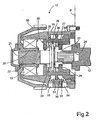
- Fig. 2
- shows a side view in partial cross-section of a preferred embodiment of a device for regulating the phase angle according to the present invention.
- Fig. 1 shows, in a perspective view in partial cross-section, an
internal combustion engine 1 with anengine block 2 withprimary cylinders channels secondary cylinders cylinder head 6 of theinternal combustion engine 1. In every primary cylinder,primary pistons primary crankshafts first crankshaft 9, and in everysecondary cylinder secondary pistons rods second crankshaft 12. Saidfirst crankshaft 9 is mounted in bearings in theengine block 2, and saidsecond crankshaft 12 is mounted in bearings in thecylinder head 6. Thecrankshafts transmission 13 comprising acogged driving belt 14 which runs over a first 15 and a second 16 driving wheel, the size of thedriving wheels second crankshaft 12 rotates with half the rpm's of thefirst crankshaft 9. Thesecond driving wheels 16 partially envelope thehousing 18 of the device forphase shift control 17 which is arranged on thecylinder head 6. - With reference to Fig. 2, a preferred embodiment of the device or
phase shift control 17 will now be described. In the embodiment shown, thesecond driving wheel 16 is mounted in thehousing 18 by means ofball bearings 19, preferably an angle contact layer with double rows. Thedriving wheel 16 is in addition equipped with agrooved portion 20, which interacts with the correspondinggrooved portion 22 on acrankshaft extension 21. Said groovedportions crankshaft extension 21. Thecrankshaft extension 21 in addition exhibits a portion equipped withsplines 23 which cooperates with acorresponding portion 24 equipped with splines on thesecond crankshaft 12 for said connection which is displaceable and fixed against rotation. The axis of rotation of thecrankshaft extension 21 thus coincides with the axis of rotation of thesecond crankshaft 12. - The
crankshaft extension 21 is made of steel and is, at thegrooved portion 22 and theportion 23, equipped with splines, covered with a layer consisting of chemically deposited nickel, which has been impregnated and surface coated with a fluoral plastic and thermically hardened. In this way, low friction is obtained, which means that reduced forces will be necessary for said phase shift control. Coatings of this kind are commercially available under the brand name Nedox®, and have previously been used, among other things, as surface coating on gear cogs and on molding tools for plastic products with small trailing angles. - The
device 17 in addition comprises means 25 to achieve the displacement of thecrankshaft extension 21. For this purpose, thecrankshaft extension 21 is thus provided with aflange 26 between said groovedportion 22 and the spline equippedportion 23, on which ahydraulic piston 27 which is displaceably arranged in thehousing 18 is arranged to work. Between theflange 26 and thehydraulic piston 27 there are arrangedbearings portions hydraulic piston 27 is arranged to surround thecrankshaft extension 21, thearrangement 17 will become compact and short in the axial direction, which is extremely advantageous in motor vehicles. - In addition, the
hydraulic piston 27 on its enveloping surface exhibits anabutment 30 which divides a chamber into a first 31 and asecond 32 an chamber, which each communicate with a first 33 and a second 34 oil conduit, respectively. Theoil conduits engine 1, controls the oil supply to one or theother sub-chamber engine 1, there is no need for an extra oil pump. - The
housing 18 is additionally provided with o-rings 35, 36, which are arranged to be in contact with thepiston 27, one on each side of saidabutment 30, and to function as oil sealings for the sub-chambers 31, 32. On the outer perimeter of theabutment 30 there is arranged a corresponding o-ring for oil sealing between said first 31 and second 32 sub-chamber. Since thecrankshaft extension 21 is connected to thepiston 27 via thebearings piston 27 when thecrankshaft extension 21 rotates. As a result of this, thepiston 27, due to friction between it and the o-rings 35, 36, 37, will not rotate with thecrankshaft extension 21 when it rotates, which simplifies said oil sealing. - According to what has been described above, the function of the
device 17 is as follows: Supply of oil through theconduit 33 to the sub-chamber 31 results in a build-up of pressure in the sub-chamber 31, whose volume is limited by theabutment 30 arranged on thepiston 27. This in turn causes thepiston 27 to be pressed in the direction of thecylinder head 6. Since thecrankshaft extension 21 via thebearings piston 27, there is thus a relative axial displacement in thespline coupling crankshaft extension 21 and thecrankshaft 12. At the same time, there is a corresponding relative axial displacement between thecrankshaft extension 21 and thesecond driving wheel 16, while thedriving wheel 16 rotates in thetrapeze grooves conduit 34 to the sub-chamber 32. - The invention is not limited to that which has been described above, other embodiments are also possible within the scope of
claim 1. Displacement of the crankshaft extension can also take place against a coil, for example a spiral coil, with said hydraulic piston only being arranged to cause displacement in one direction. According to an alternative embodiment, the crankshaft extension is arranged in the opposite direction, so that said spline coupling can be arranged at the second driving wheel, and said trapeze groove is arranged between the crankshaft extension and the second crankshaft. In yet another alternative embodiment, the device for control of phase angle, in contrast to the above described embodiment, is arranged at the first crankshaft. Finally, the crankshaft extension can, instead of said splines, be equipped with another cross-section, for example a square cross-section which interacts with a corresponding square hole on the crankshaft for obtaining said displaceable connection which is fixed against rotation.
Claims (7)
- Device (17) for controlling the phase angle between a first (9) and a second (12) crankshaft of an internal combustion engine (1), said internal combustion engine (1) comprising at least one primary cylinder (3a, 3b, 3c, 3d) which communicates with at least one secondary cylinder (5a, 5b, 5c, 5d), in each primary cylinder (3a, 3b, 3c, 3d) there being movingly arranged a primary piston (7a, 7b, 7c, 7d) which is connected to the first crankshaft (9), and in every secondary cylinder (5a, 5b, 5c, 5d) there being movingly arranged a secondary piston (10a, 10b, 10c, 10d) which is connected to the second crankshaft (12), with said first (9) and second (12) crankshaft being connected to each other by means of a transmission (13), with the device (17) comprising means (25) for obtaining the phase shift control, and a crankshaft extension (21) intended for said phase angle control, which is connected fixed against rotation to one of said crankshafts (9, 12) and rotationally attached to the second of said crankshafts (9, 12) characterized in that said means (25) comprises a hydraulic piston (27) arranged in a housing (18), said hydraulic piston (27) being arranged to obtain an axial displacement of the crankshaft extension (21) relative to one of said crankshafts (9, 12), said hydraulic piston being arranged to surround the crankshaft extension (21).
- Device according to claim 1,
characterized in that said hydraulic piston (27) is arranged for obtaining axial displacement of the crankshaft extension (21) in a first direction and in a second direction. - Device according to claim 1 or 2, characterized in that said hydraulic piston (27) is arranged rotationally fixed relative to said housing (18).
- Device according to any of claims 1-3 characterized in that said crankshaft extension (21) exhibits a first portion (23) equipped with splines for said connection fixed against rotation.
- Device according to claim 4
characterized in that said first portion (23) is arranged to admit said axial displacement. - Device according to claim 4 or 5, characterized in that said crankshaft extension (21) exhibits a second portion (22) equipped with grooves for said rataficnal connection.
- Device according to claim 6,
characterized in that said crankshaft extension (21) exhibits a flange (26) between said first and second portions (22, 23) with the hydraulic piston (27) being arranged to affect said flange (26).
Applications Claiming Priority (3)
| Application Number | Priority Date | Filing Date | Title |
|---|---|---|---|
| SE0002088A SE522629C2 (en) | 2000-06-05 | 2000-06-05 | Apparatus for controlling the phase angle between a first and a second crankshaft |
| SE0002088 | 2000-06-05 | ||
| PCT/SE2001/001233 WO2001094766A1 (en) | 2000-06-05 | 2001-06-01 | Device for controlling the phase angle between a first and a second crankshaft |
Publications (2)
| Publication Number | Publication Date |
|---|---|
| EP1292762A1 EP1292762A1 (en) | 2003-03-19 |
| EP1292762B1 true EP1292762B1 (en) | 2006-08-09 |
Family
ID=20279965
Family Applications (1)
| Application Number | Title | Priority Date | Filing Date |
|---|---|---|---|
| EP01937105A Expired - Lifetime EP1292762B1 (en) | 2000-06-05 | 2001-06-01 | Device for controlling the phase angle between a first and a second crankshaft |
Country Status (8)
| Country | Link |
|---|---|
| US (1) | US6763787B2 (en) |
| EP (1) | EP1292762B1 (en) |
| AT (1) | ATE335922T1 (en) |
| AU (1) | AU2001262870A1 (en) |
| DE (1) | DE60122142T2 (en) |
| ES (1) | ES2271018T3 (en) |
| SE (1) | SE522629C2 (en) |
| WO (1) | WO2001094766A1 (en) |
Cited By (3)
| Publication number | Priority date | Publication date | Assignee | Title |
|---|---|---|---|---|
| US20220112848A1 (en) * | 2020-10-12 | 2022-04-14 | Schaeffler Technologies AG & Co., KG | Actuation assembly for phaser system |
| US20220252015A1 (en) * | 2021-02-11 | 2022-08-11 | Schaeffler Technologies AG & Co. KG | Cranktrain phase adjuster for variable compression ratio |
| US11428173B2 (en) * | 2020-10-06 | 2022-08-30 | Schaeffler Technologies AG & Co. KG | Cranktrain phase adjuster for variable compression ratio |
Families Citing this family (21)
| Publication number | Priority date | Publication date | Assignee | Title |
|---|---|---|---|---|
| SE522629C2 (en) | 2000-06-05 | 2004-02-24 | Volvo Lastvagnar Ab | Apparatus for controlling the phase angle between a first and a second crankshaft |
| WO2010143998A1 (en) * | 2009-06-10 | 2010-12-16 | Alvare Engine Ab | Engine control method |
| US8439010B2 (en) | 2010-11-03 | 2013-05-14 | Edwin M. Fernandez | Internal combustion engine |
| US8555838B2 (en) | 2010-12-01 | 2013-10-15 | Caterpillar Inc. | Engine with stub shaft supported cam gear and machine using same |
| US9513045B2 (en) | 2012-05-03 | 2016-12-06 | Whirlpool Corporation | Heater-less ice maker assembly with a twistable tray |
| US8925335B2 (en) | 2012-11-16 | 2015-01-06 | Whirlpool Corporation | Ice cube release and rapid freeze using fluid exchange apparatus and methods |
| US9518770B2 (en) | 2012-12-13 | 2016-12-13 | Whirlpool Corporation | Multi-sheet spherical ice making |
| US9476629B2 (en) | 2012-12-13 | 2016-10-25 | Whirlpool Corporation | Clear ice maker and method for forming clear ice |
| US9500398B2 (en) | 2012-12-13 | 2016-11-22 | Whirlpool Corporation | Twist harvest ice geometry |
| US9557087B2 (en) | 2012-12-13 | 2017-01-31 | Whirlpool Corporation | Clear ice making apparatus having an oscillation frequency and angle |
| US9273891B2 (en) | 2012-12-13 | 2016-03-01 | Whirlpool Corporation | Rotational ice maker |
| US9599385B2 (en) | 2012-12-13 | 2017-03-21 | Whirlpool Corporation | Weirless ice tray |
| US9410723B2 (en) | 2012-12-13 | 2016-08-09 | Whirlpool Corporation | Ice maker with rocking cold plate |
| US9303903B2 (en) | 2012-12-13 | 2016-04-05 | Whirlpool Corporation | Cooling system for ice maker |
| US9470448B2 (en) | 2012-12-13 | 2016-10-18 | Whirlpool Corporation | Apparatus to warm plastic side of mold |
| US9310115B2 (en) | 2012-12-13 | 2016-04-12 | Whirlpool Corporation | Layering of low thermal conductive material on metal tray |
| US9518773B2 (en) | 2012-12-13 | 2016-12-13 | Whirlpool Corporation | Clear ice maker |
| US9599388B2 (en) | 2012-12-13 | 2017-03-21 | Whirlpool Corporation | Clear ice maker with varied thermal conductivity |
| WO2016065269A2 (en) | 2014-10-23 | 2016-04-28 | Whirlpool Corporation | Method and apparatus for increasing rate of ice production in an automatic ice maker |
| US10739053B2 (en) | 2017-11-13 | 2020-08-11 | Whirlpool Corporation | Ice-making appliance |
| US10907874B2 (en) | 2018-10-22 | 2021-02-02 | Whirlpool Corporation | Ice maker downspout |
Family Cites Families (20)
| Publication number | Priority date | Publication date | Assignee | Title |
|---|---|---|---|---|
| US4104995A (en) * | 1976-12-15 | 1978-08-08 | Rolf Steinbock | Variable compression engine |
| DE3127766A1 (en) * | 1981-07-14 | 1983-01-27 | Atlas Aluminium-Fahrzeugtechnik Gmbh, 5980 Werdohl | "CAMSHAFT CONTROL UNIT" |
| US4577598A (en) * | 1982-04-09 | 1986-03-25 | Ford Motor Company | Internal combustion engine and cam drive mechanism therefor |
| LU84574A1 (en) * | 1983-01-04 | 1984-10-24 | Gilbert Van Avermaete | COMBUSTION ENGINE |
| DE3320835A1 (en) * | 1983-06-09 | 1984-12-13 | Dieter 7460 Balingen Fuoß | Multi-position drive |
| DE3616234A1 (en) * | 1986-05-14 | 1987-11-19 | Bayerische Motoren Werke Ag | DEVICE FOR THE RELATIVE TURNING CHANGE OF TWO DRIVELY CONNECTED SHAFTS, ESPECIALLY BETWEEN A CRANKSHAFT AND CAMSHAFT BEARING IN A MACHINE HOUSING OF AN INTERNAL COMBUSTION ENGINE |
| SE463929B (en) * | 1989-06-20 | 1991-02-11 | Skaerblacka Bil & Motor Ab | DEVICE FOR A COMBUSTION ENGINE |
| DE4014143A1 (en) * | 1990-05-02 | 1991-11-28 | Schneider Gesenkschmiede | CONNECTION BETWEEN A FIRST ROTATIONAL PART AND A SECOND ROTATIONAL PART |
| DE4023853A1 (en) * | 1990-07-27 | 1992-01-30 | Audi Ag | VALVE CONTROLLED INTERNAL COMBUSTION ENGINE |
| LU88235A1 (en) * | 1993-03-19 | 1994-10-03 | Gilbert Van Avermaete | Improvements made to four-stroke internal combustion engines, with variable volumetric ratio allowing high rates of boost pressure and operating by compression ignition or by controlled ignition |
| JPH0777073A (en) * | 1993-09-09 | 1995-03-20 | Toyota Motor Corp | Valve timing control device for internal combustion engine |
| DE4405704A1 (en) * | 1994-02-23 | 1995-08-24 | Bayerische Motoren Werke Ag | Meshing control for transmission |
| JP4316797B2 (en) * | 1998-02-27 | 2009-08-19 | バイエリツシエ・モトーレン・ヴエルケ・アクチエンゲゼルシヤフト | Device for adjusting the movement process of a gas exchange valve of an internal combustion engine |
| AUPP330998A0 (en) * | 1998-05-04 | 1998-05-28 | Bentley, Paul Joseph | Variable duration, overlap and cam timing |
| US6260520B1 (en) * | 1998-11-16 | 2001-07-17 | Ford Global Technologies | Homogeneous charge compression ignition internal combustion engine |
| JP2001065371A (en) * | 1999-08-24 | 2001-03-13 | Toyota Motor Corp | Variable valve train for internal combustion engine |
| US6216654B1 (en) * | 1999-08-27 | 2001-04-17 | Daimlerchrysler Corporation | Phase changing device |
| US6199522B1 (en) * | 1999-08-27 | 2001-03-13 | Daimlerchrysler Corporation | Camshaft phase controlling device |
| JP3799944B2 (en) * | 2000-03-21 | 2006-07-19 | トヨタ自動車株式会社 | Variable valve mechanism and intake air amount control device for internal combustion engine |
| SE522629C2 (en) | 2000-06-05 | 2004-02-24 | Volvo Lastvagnar Ab | Apparatus for controlling the phase angle between a first and a second crankshaft |
-
2000
- 2000-06-05 SE SE0002088A patent/SE522629C2/en not_active IP Right Cessation
-
2001
- 2001-06-01 AT AT01937105T patent/ATE335922T1/en not_active IP Right Cessation
- 2001-06-01 DE DE60122142T patent/DE60122142T2/en not_active Expired - Lifetime
- 2001-06-01 AU AU2001262870A patent/AU2001262870A1/en not_active Abandoned
- 2001-06-01 EP EP01937105A patent/EP1292762B1/en not_active Expired - Lifetime
- 2001-06-01 WO PCT/SE2001/001233 patent/WO2001094766A1/en not_active Ceased
- 2001-06-01 ES ES01937105T patent/ES2271018T3/en not_active Expired - Lifetime
-
2002
- 2002-12-05 US US10/065,973 patent/US6763787B2/en not_active Expired - Lifetime
Cited By (5)
| Publication number | Priority date | Publication date | Assignee | Title |
|---|---|---|---|---|
| US11428173B2 (en) * | 2020-10-06 | 2022-08-30 | Schaeffler Technologies AG & Co. KG | Cranktrain phase adjuster for variable compression ratio |
| US20220112848A1 (en) * | 2020-10-12 | 2022-04-14 | Schaeffler Technologies AG & Co., KG | Actuation assembly for phaser system |
| US11619182B2 (en) * | 2020-10-12 | 2023-04-04 | Schaeffler Technologies AG & Co. KG | Actuation assembly for phaser system |
| US20220252015A1 (en) * | 2021-02-11 | 2022-08-11 | Schaeffler Technologies AG & Co. KG | Cranktrain phase adjuster for variable compression ratio |
| US11519342B2 (en) * | 2021-02-11 | 2022-12-06 | Schaeffler Technologies AG & Co. KG | Cranktrain phase adjuster for variable compression ratio |
Also Published As
| Publication number | Publication date |
|---|---|
| SE0002088L (en) | 2001-12-06 |
| US20030111028A1 (en) | 2003-06-19 |
| ES2271018T3 (en) | 2007-04-16 |
| EP1292762A1 (en) | 2003-03-19 |
| SE0002088D0 (en) | 2000-06-05 |
| DE60122142T2 (en) | 2007-06-28 |
| DE60122142D1 (en) | 2006-09-21 |
| SE522629C2 (en) | 2004-02-24 |
| ATE335922T1 (en) | 2006-09-15 |
| AU2001262870A1 (en) | 2001-12-17 |
| US6763787B2 (en) | 2004-07-20 |
| WO2001094766A1 (en) | 2001-12-13 |
Similar Documents
| Publication | Publication Date | Title |
|---|---|---|
| US6763787B2 (en) | Device for controlling the phase angle between a first and a second crankshaft | |
| US6173684B1 (en) | Internal combustion valve operating mechanism | |
| US6260532B1 (en) | Rigid crankshaft cradle and actuator | |
| CA1240576A (en) | Phasing device for machinery applications | |
| US4174684A (en) | Variable stroke internal combustion engine | |
| US5623894A (en) | Dual compression and dual expansion engine | |
| US8613269B2 (en) | Internal combustion engine with direct air injection | |
| US10267225B2 (en) | Internal combustion engine | |
| US20130228150A1 (en) | Rotary, Internal Combustion Engine | |
| US4555003A (en) | Split engine clutch | |
| JP2001516837A (en) | Variable compression piston assembly | |
| US4515113A (en) | Swash plate engine | |
| EP1082528B1 (en) | Rigid crankshaft cradle and actuator | |
| CN106870052B (en) | Variable compression ratio mechanism of engine and valve system matched with variable compression ratio mechanism | |
| US4799462A (en) | Hydraulic valve drive for internal combustion engines | |
| Welsh et al. | The Variable-Displacement Engine: An Advanced Concept Powerplant | |
| US5617826A (en) | Synchronized compression ignition engine | |
| US4557232A (en) | Swash plate engine | |
| RU2013603C1 (en) | Internal combustion engine with variable compression ratio | |
| JP3106171B2 (en) | Crankless engine mechanism | |
| US6454544B2 (en) | Pump for conveying fuel in an internal combustion engine | |
| CA2093954A1 (en) | Power transmitting device | |
| CN107035455B (en) | Adjustable hydraulic gear shaft transmission mechanism | |
| US10563575B2 (en) | Arrangement of a switching valve module in a connecting rod of a reciprocating internal combustion engine | |
| JPS5915665A (en) | Fuel injection device |
Legal Events
| Date | Code | Title | Description |
|---|---|---|---|
| PUAI | Public reference made under article 153(3) epc to a published international application that has entered the european phase |
Free format text: ORIGINAL CODE: 0009012 |
|
| 17P | Request for examination filed |
Effective date: 20030107 |
|
| AK | Designated contracting states |
Kind code of ref document: A1 Designated state(s): AT BE CH CY DE DK ES FI FR GB GR IE IT LI LU MC NL PT SE TR |
|
| AX | Request for extension of the european patent |
Extension state: AL LT LV MK RO SI |
|
| TPAC | Observations filed by third parties |
Free format text: ORIGINAL CODE: EPIDOSNTIPA |
|
| GRAP | Despatch of communication of intention to grant a patent |
Free format text: ORIGINAL CODE: EPIDOSNIGR1 |
|
| GRAF | Information related to payment of grant fee modified |
Free format text: ORIGINAL CODE: EPIDOSCIGR3 |
|
| GRAS | Grant fee paid |
Free format text: ORIGINAL CODE: EPIDOSNIGR3 |
|
| GRAA | (expected) grant |
Free format text: ORIGINAL CODE: 0009210 |
|
| RAP1 | Party data changed (applicant data changed or rights of an application transferred) |
Owner name: ALVAR ENGINE AB |
|
| RIN1 | Information on inventor provided before grant (corrected) |
Inventor name: NILSSON, STEFAN Inventor name: KRISTIANSSON, BO Inventor name: RYDBERG, ANDERS Inventor name: HALLENSTVEDT, ODDBJOERN |
|
| AK | Designated contracting states |
Kind code of ref document: B1 Designated state(s): AT BE CH CY DE DK ES FI FR GB GR IE IT LI LU MC NL PT SE TR |
|
| PG25 | Lapsed in a contracting state [announced via postgrant information from national office to epo] |
Ref country code: IT Free format text: LAPSE BECAUSE OF FAILURE TO SUBMIT A TRANSLATION OF THE DESCRIPTION OR TO PAY THE FEE WITHIN THE PRESCRIBED TIME-LIMIT;WARNING: LAPSES OF ITALIAN PATENTS WITH EFFECTIVE DATE BEFORE 2007 MAY HAVE OCCURRED AT ANY TIME BEFORE 2007. THE CORRECT EFFECTIVE DATE MAY BE DIFFERENT FROM THE ONE RECORDED. Effective date: 20060809 Ref country code: FI Free format text: LAPSE BECAUSE OF FAILURE TO SUBMIT A TRANSLATION OF THE DESCRIPTION OR TO PAY THE FEE WITHIN THE PRESCRIBED TIME-LIMIT Effective date: 20060809 Ref country code: CH Free format text: LAPSE BECAUSE OF FAILURE TO SUBMIT A TRANSLATION OF THE DESCRIPTION OR TO PAY THE FEE WITHIN THE PRESCRIBED TIME-LIMIT Effective date: 20060809 Ref country code: AT Free format text: LAPSE BECAUSE OF FAILURE TO SUBMIT A TRANSLATION OF THE DESCRIPTION OR TO PAY THE FEE WITHIN THE PRESCRIBED TIME-LIMIT Effective date: 20060809 Ref country code: BE Free format text: LAPSE BECAUSE OF FAILURE TO SUBMIT A TRANSLATION OF THE DESCRIPTION OR TO PAY THE FEE WITHIN THE PRESCRIBED TIME-LIMIT Effective date: 20060809 Ref country code: LI Free format text: LAPSE BECAUSE OF FAILURE TO SUBMIT A TRANSLATION OF THE DESCRIPTION OR TO PAY THE FEE WITHIN THE PRESCRIBED TIME-LIMIT Effective date: 20060809 Ref country code: NL Free format text: LAPSE BECAUSE OF FAILURE TO SUBMIT A TRANSLATION OF THE DESCRIPTION OR TO PAY THE FEE WITHIN THE PRESCRIBED TIME-LIMIT Effective date: 20060809 |
|
| REG | Reference to a national code |
Ref country code: GB Ref legal event code: FG4D |
|
| REG | Reference to a national code |
Ref country code: CH Ref legal event code: EP |
|
| REG | Reference to a national code |
Ref country code: IE Ref legal event code: FG4D |
|
| REF | Corresponds to: |
Ref document number: 60122142 Country of ref document: DE Date of ref document: 20060921 Kind code of ref document: P |
|
| PG25 | Lapsed in a contracting state [announced via postgrant information from national office to epo] |
Ref country code: DK Free format text: LAPSE BECAUSE OF FAILURE TO SUBMIT A TRANSLATION OF THE DESCRIPTION OR TO PAY THE FEE WITHIN THE PRESCRIBED TIME-LIMIT Effective date: 20061109 Ref country code: SE Free format text: LAPSE BECAUSE OF FAILURE TO SUBMIT A TRANSLATION OF THE DESCRIPTION OR TO PAY THE FEE WITHIN THE PRESCRIBED TIME-LIMIT Effective date: 20061109 |
|
| PG25 | Lapsed in a contracting state [announced via postgrant information from national office to epo] |
Ref country code: PT Free format text: LAPSE BECAUSE OF FAILURE TO SUBMIT A TRANSLATION OF THE DESCRIPTION OR TO PAY THE FEE WITHIN THE PRESCRIBED TIME-LIMIT Effective date: 20070109 |
|
| NLV1 | Nl: lapsed or annulled due to failure to fulfill the requirements of art. 29p and 29m of the patents act | ||
| REG | Reference to a national code |
Ref country code: CH Ref legal event code: PL |
|
| ET | Fr: translation filed | ||
| REG | Reference to a national code |
Ref country code: ES Ref legal event code: FG2A Ref document number: 2271018 Country of ref document: ES Kind code of ref document: T3 |
|
| PLBE | No opposition filed within time limit |
Free format text: ORIGINAL CODE: 0009261 |
|
| STAA | Information on the status of an ep patent application or granted ep patent |
Free format text: STATUS: NO OPPOSITION FILED WITHIN TIME LIMIT |
|
| 26N | No opposition filed |
Effective date: 20070510 |
|
| PG25 | Lapsed in a contracting state [announced via postgrant information from national office to epo] |
Ref country code: MC Free format text: LAPSE BECAUSE OF NON-PAYMENT OF DUE FEES Effective date: 20070630 |
|
| PG25 | Lapsed in a contracting state [announced via postgrant information from national office to epo] |
Ref country code: GR Free format text: LAPSE BECAUSE OF FAILURE TO SUBMIT A TRANSLATION OF THE DESCRIPTION OR TO PAY THE FEE WITHIN THE PRESCRIBED TIME-LIMIT Effective date: 20061110 |
|
| PG25 | Lapsed in a contracting state [announced via postgrant information from national office to epo] |
Ref country code: IE Free format text: LAPSE BECAUSE OF NON-PAYMENT OF DUE FEES Effective date: 20070601 |
|
| PG25 | Lapsed in a contracting state [announced via postgrant information from national office to epo] |
Ref country code: LU Free format text: LAPSE BECAUSE OF NON-PAYMENT OF DUE FEES Effective date: 20070601 Ref country code: CY Free format text: LAPSE BECAUSE OF FAILURE TO SUBMIT A TRANSLATION OF THE DESCRIPTION OR TO PAY THE FEE WITHIN THE PRESCRIBED TIME-LIMIT Effective date: 20060809 |
|
| PG25 | Lapsed in a contracting state [announced via postgrant information from national office to epo] |
Ref country code: TR Free format text: LAPSE BECAUSE OF FAILURE TO SUBMIT A TRANSLATION OF THE DESCRIPTION OR TO PAY THE FEE WITHIN THE PRESCRIBED TIME-LIMIT Effective date: 20060809 |
|
| REG | Reference to a national code |
Ref country code: FR Ref legal event code: PLFP Year of fee payment: 16 |
|
| REG | Reference to a national code |
Ref country code: FR Ref legal event code: PLFP Year of fee payment: 17 |
|
| REG | Reference to a national code |
Ref country code: FR Ref legal event code: PLFP Year of fee payment: 18 |
|
| PGFP | Annual fee paid to national office [announced via postgrant information from national office to epo] |
Ref country code: DE Payment date: 20180619 Year of fee payment: 18 |
|
| PGFP | Annual fee paid to national office [announced via postgrant information from national office to epo] |
Ref country code: IT Payment date: 20180620 Year of fee payment: 18 Ref country code: FR Payment date: 20180615 Year of fee payment: 18 |
|
| PGFP | Annual fee paid to national office [announced via postgrant information from national office to epo] |
Ref country code: ES Payment date: 20180702 Year of fee payment: 18 Ref country code: GB Payment date: 20180618 Year of fee payment: 18 |
|
| REG | Reference to a national code |
Ref country code: DE Ref legal event code: R119 Ref document number: 60122142 Country of ref document: DE |
|
| GBPC | Gb: european patent ceased through non-payment of renewal fee |
Effective date: 20190601 |
|
| PG25 | Lapsed in a contracting state [announced via postgrant information from national office to epo] |
Ref country code: GB Free format text: LAPSE BECAUSE OF NON-PAYMENT OF DUE FEES Effective date: 20190601 Ref country code: DE Free format text: LAPSE BECAUSE OF NON-PAYMENT OF DUE FEES Effective date: 20200101 Ref country code: IT Free format text: LAPSE BECAUSE OF NON-PAYMENT OF DUE FEES Effective date: 20190601 |
|
| PG25 | Lapsed in a contracting state [announced via postgrant information from national office to epo] |
Ref country code: FR Free format text: LAPSE BECAUSE OF NON-PAYMENT OF DUE FEES Effective date: 20190630 |
|
| REG | Reference to a national code |
Ref country code: ES Ref legal event code: FD2A Effective date: 20201027 |
|
| PG25 | Lapsed in a contracting state [announced via postgrant information from national office to epo] |
Ref country code: ES Free format text: LAPSE BECAUSE OF NON-PAYMENT OF DUE FEES Effective date: 20190602 |