EP1292158A1 - Call re-establishment method and exchange nodes therefor - Google Patents
Call re-establishment method and exchange nodes therefor Download PDFInfo
- Publication number
- EP1292158A1 EP1292158A1 EP01410111A EP01410111A EP1292158A1 EP 1292158 A1 EP1292158 A1 EP 1292158A1 EP 01410111 A EP01410111 A EP 01410111A EP 01410111 A EP01410111 A EP 01410111A EP 1292158 A1 EP1292158 A1 EP 1292158A1
- Authority
- EP
- European Patent Office
- Prior art keywords
- node
- call
- connection
- pivot
- operable
- Prior art date
- Legal status (The legal status is an assumption and is not a legal conclusion. Google has not performed a legal analysis and makes no representation as to the accuracy of the status listed.)
- Granted
Links
Images




Classifications
-
- H—ELECTRICITY
- H04—ELECTRIC COMMUNICATION TECHNIQUE
- H04M—TELEPHONIC COMMUNICATION
- H04M3/00—Automatic or semi-automatic exchanges
- H04M3/22—Arrangements for supervision, monitoring or testing
- H04M3/2254—Arrangements for supervision, monitoring or testing in networks
-
- H—ELECTRICITY
- H04—ELECTRIC COMMUNICATION TECHNIQUE
- H04Q—SELECTING
- H04Q3/00—Selecting arrangements
- H04Q3/0016—Arrangements providing connection between exchanges
- H04Q3/0025—Provisions for signalling
-
- H—ELECTRICITY
- H04—ELECTRIC COMMUNICATION TECHNIQUE
- H04Q—SELECTING
- H04Q3/00—Selecting arrangements
- H04Q3/0016—Arrangements providing connection between exchanges
- H04Q3/0029—Provisions for intelligent networking
Definitions
- This invention relates to an exchange node, an intermediate node, a network and a method of re-establishing a call session particularly but not exclusively for providing re-establishment of a call session in the event of a network fault.
- a public switched telephone network conventionally comprises a plurality of nodes, or exchanges, which are interconnected by trunks which provide the call-carrying capacity of the network.
- the nodes are also interconnected by a signalling layer which handles the routing of calls and co-ordination of the nodes.
- an originating node to which the user device is connected transmits an initial address message (IAM) to a node in a forward direction of the call, i.e. towards a destination node.
- IAM initial address message
- forward direction is intended to refer to a direction away from the originating node towards the destination node
- backward direction is intended to refer to a direction away from the destination node and towards the originating node.
- a "forward connection” of a node is a connection between the node and a further node in the forward direction of the node
- a “backward connection” of a node refers to a connection between the node and a further node in the backward direction of the node
- “Call session” refers to the connection or connections between nodes necessary to connect the originating node and destination node.
- the IAM includes codes identifying the originating node, the destination node, a circuit identification code for the trunk to be used and the dialled digits.
- the forward node reserves the voice circuit identified by the circuit identification code for the trunk between the originating node and forward node and sends an acknowledgement, an address complete message (ACM), in the backward direction to the originating node.
- ACM address complete message
- a node When a call session ends, a node will release the relevant trunk circuit and send a release instruction (REL) to the other node connected to the trunk. The other node will likewise release the trunk circuit and send a release complete (RLC) message.
- REL release instruction
- RLC release complete
- Tromboning a phenomenon known as "tromboning" Tromboning is likely to arise in situations such as call forwarding where a call is routed to a destination exchange and then returned from the destination exchange, tying up network resources unnecessarily.
- Tromboning is also associated with number portability, and can also occur in other situations such as establishing conference calls, or establishing calls to roaming numbers in a mobile telecommunications network for example as discussed in US 5884179.
- pivot routing provides a general mechanism that can be invoked by an exchange or node in a network that decides that a call session should be sent to a called number other than that identified in the initial address message and where it is desirable to release the invoking exchange from the call path.
- an exchange can forward the information that it has the capacity to perform pivot routing
- An exchange in the forward direction of the call can send a pivot request invoking this pivot capacity.
- the pivot request includes a redirection number to which the call should be redirected and optionally, instructions that the pivot call should be returned to the invoking exchange and a returned call identifier.
- the pivot exchange can forward the call to the redirection number, or alternatively request a preceding exchange which also has a pivot routing capability to route the call session to the alternative called number.
- ITU-T Q730 also specifies a further capability, call redirection, which provides the same functionality as pivot routing in that a call may be released to a different number at a node's request, and returned to that node.
- the capability is suggested for use when the node requesting redirection retains some interest in the call.
- Each trunk in a network carries a large number of voice circuits, so that each trunk can provide a leg of a large number of call sessions.
- a network element for example a trunk or a node
- the PSTN conventionally has a plurality of duplicate elements allowing a call session to be switched from a failing element to a backup element.
- each pair of nodes is generally connected by two trunks, a main trunk and a backup trunk.
- the node at each end of the trunk detects the failure and transfers all call sessions to the backup trunk.
- This approach requires duplication of costly hardware, the provision of appropriate control technology, and the provision of an idle trunk connection.
- An aim of the present invention is to reduce or overcome the above problem.
- an exchange node operable to re-establish a call session, the exchange node being operable to establish a backward connection comprising part of a call session, and on the occurrence of a fault to transmit a pivot request to a pivot node in a backward direction of the fault, the pivot request comprising a redirection request, a call identifier, and instructions to establish a return connection between the pivot node and a nominated node.
- the exchange node may comprise the nominated node, and the exchange node may be operable on establishment of the return connection to receive the call identifier, read the call identifier and re-establish the call session.
- the exchange node may be operable to maintain the forward connection on occurrence of the fault and to connect the return connection to the forward connection.
- the exchange node may be operable to release the backward connection on receipt of a release instruction from the pivot node.
- the exchange node may be operable to transmit a fault notification to the nominated node, the fault notification comprising the call identifier.
- the exchange node may be operable to release the backward connection on receipt of a release instruction from the pivot node and to release the forward connection.
- the exchange node may be operable to transmit the pivot request in a occurrence of a fault in a backward direction of a node.
- the exchange node may comprise a plurality of elements and the exchange node may be operable to transmit a pivot request in the event of failure of one of said elements such that the return connection is established to another of the elements.
- the exchange node may be operable to detect the occurrence of a fault in the backward connection.
- the exchange node may be operable to receive a fault notification from an intermediate node.
- an exchange node operable to establish a backward connection comprising part of a call session, the exchange node being operable to receive a fault notification comprising a call identifier, receive a return connection identified by the call identifier and re-establish the call session.
- an exchange node operable to establish a forward connection and a backward connection, the forward connection and backward connection comprising part of a call session, the exchange node being operable to detect the occurrence of a fault in the backward connection, and transmit a fault notification to a forward node.
- a fourth aspect of the invention we provide a network provided with at least one of an exchange node according to the first aspect of the invention, an exchange node according to the second aspect of the invention and an exchange node according to the third aspect of the invention.
- a fifth aspect of the invention we provide a method of re-establishing a call session comprising a backward connection, the method comprising the steps of, on occurrence of a fault, transmitting a pivot request to a pivot node in the backward direction of the fault, the pivot request comprising; a redirection request, a call identifier, andinstructions to establish a return connection.
- the method may comprise the steps of receiving the return connection, receiving the call identifier and re-establishing the call session.
- the step of re-establishing the call session may comprise the step of connecting the return connection and the forward connection.
- the method may comprise the step of releasing the backward connection
- a sixth aspect of the invention we provide a method of re-establishing a call session comprising a forward connection and a backward connection comprising the steps of detecting a fault in the backward connection, and transmitting a fault notification to a forward node.
- the present invention thus makes use of the pivot re-routing capability to enable a disrupted call sessions to be re-established by re-routing the call around a failed network element.
- a prior art network is generally indicated at 10 comprising an originating node 11, a terminating node 12, a first intermediate node 13, and a second intermediate node 14.
- the network is provided with a signalling layer 15, to which each node 11, 12, 13, 14 is connected by signalling links 11 a , 12 a , 13 a , 14 a respectively.
- the nodes 11, 12, 13, 14 are interconnected by main trunks 16 and backup trunks 17.
- the originating node 11, terminating node 12 and intermediate nodes 13, 14 all comprise service switching points (SSP's).
- the signalling links 13 a , 14 a , 15 a , 16 a comprise type "A" links connecting each SSP to a corresponding signal transfer point (STP) (not shown) which forms part of the signalling layer 15.
- STP signal transfer point
- Each node 11, 12, 13, 14 is provided with automatic protection switching means 11 b , 12 b , 13 b , 14 b respectively operable to detect a fault in the main trunk 16 and to switch to the backup trunk 17.
- the call is routed from the originating node 11 to the terminating node 12 via one or both of the intermediate nodes 13, 14 in conventional manner, for example using the ISDN User Part (ISUP) protocol or using an Intelligent Network (IN) protocol or by other conventional means as appropriate.
- the network 10 may be provided with pivot routing means of known type as desired.
- pivot routing in conventional manner may be used to remove the routing to and from the intermediate node 13.
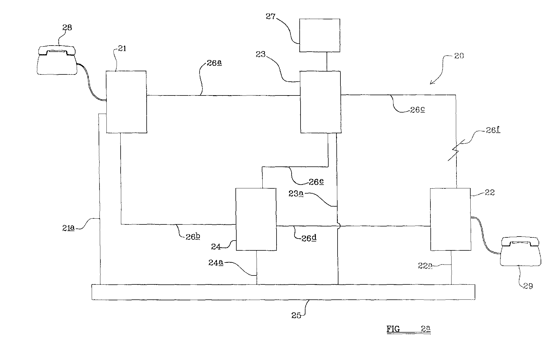
- a network 20 comprising at least one exchange node embodying the present invention is shown.
- the network 20 is provided with an originating node 21, a terminating node 22 comprising an exchange mode embodying the present invention, a first intermediate node 23, a second intermediate node 24 and a signalling layer 25.
- the nodes 21, 22, 23, 24 are connected to the signalling layer 25 by signalling links 21 a , 22 a , 23 a , 24 a respectively.
- the originating node is connected to the first intermediate node 23 and the second intermediate node 24 by trunks 26 a , 26 b respectively.
- the terminating node 22 is similarly connected to the first intermediate node 23 and second intermediate node 24 by trunks 26 c , 26 d respectively.
- the first intermediate node 23 and second intermediate node 24 are interconnected by a trunk 26 e .
- the network 20 in the present example is also provided with a service node 27, in the present example connected to the intermediate node 23.
- the network 20 When a call is made from an originating telephone or other device 28 to a destination telephone or other device 29, the network 20 functions in like manner to the network shown in 10.
- the nodes of the network 20 are however connected by single trunks, i.c. there are no redundant trunks, and no automatic protection switching means is therefore provided at each node.
- An exchange node according to the first aspect of the present invention is provided as the terminating node 22, and at least the first intermediate node 23 is provided with a pivot routing capacity of standard type as described hereinbefore.
- a call session has been established in conventional manner from the telephone 28 to the telephone 29 via the originating node 21, first intermediate node 23 and terminating node 22.
- the terminating node 22 thus establishes a forward connection to the destination telephone 29 and a backward connection on trunk 26 c to the first intermediate node 23.
- a fault 26 f develops on trunk 26 c , which is detected by the terminating node 22.
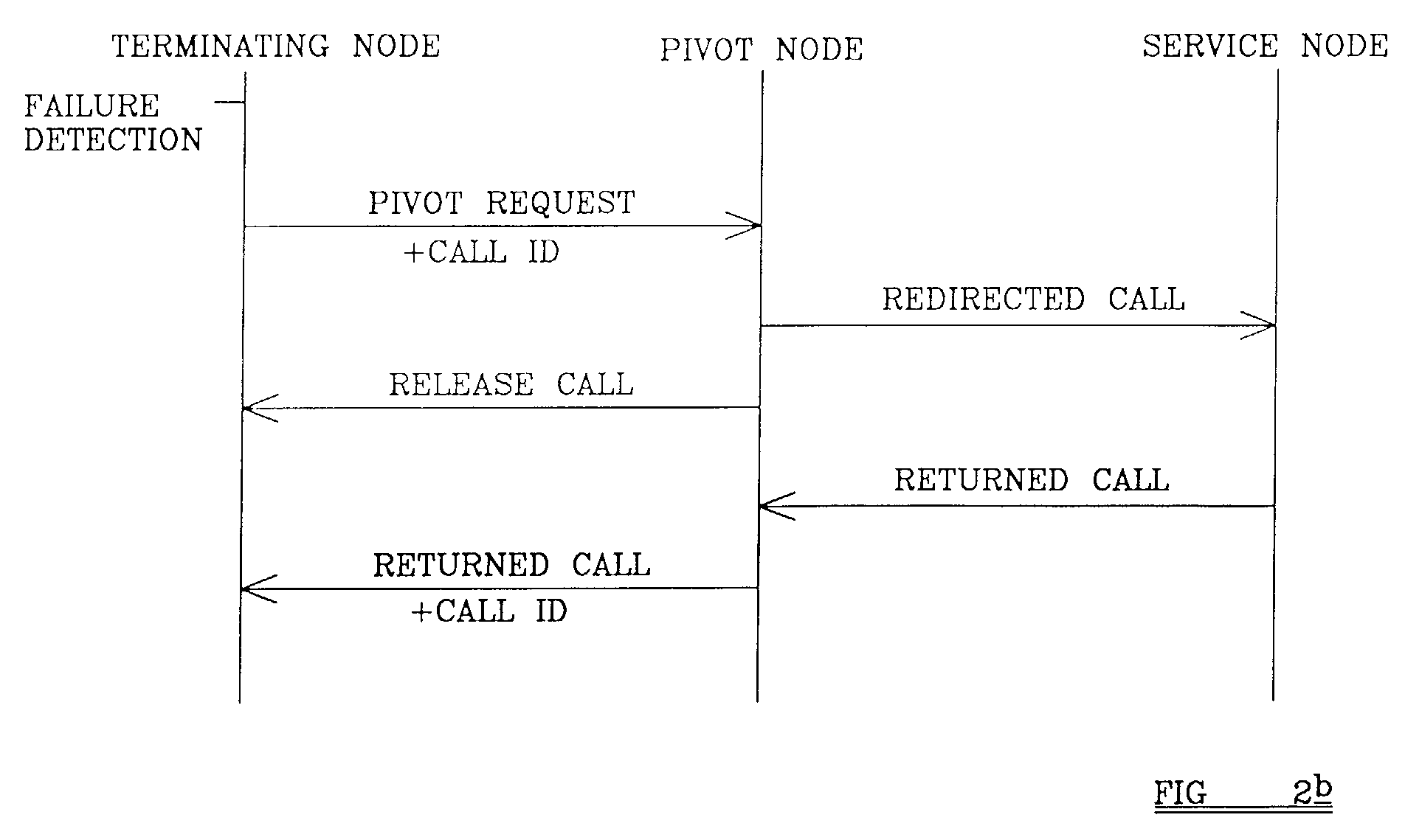
- the terminating node 22 sends a pivot request via the signalling link 22 a , signalling network 25 and signalling link 23 a to the first intermediate node 23.
- the pivot request carries a redirection request to a particular network address, in this case the address of the service node 27, a call identifier, and instructions to return the call to a nominated node, in this example, the invoking node, i.e. the terminating node 22.
- the first intermediate node 23 receives the pivot request, and assuming it is valid, re-directs the call to the service node 27.
- the first intermediate node 23 releases the connection to trunk 26 c , and sends a release instruction to the terminating node 22 to do likewise.
- the terminating node 22 maintains the forward connection to the telephone 29, and associates the forward connection with the call identifier.
- the redirected call may be treated by the service node 27 as a null call, returning the call to the first intermediate node 23 without performing any other action.
- the first intermediate node 23 then will attempt to re-connect the call to the terminating node 22 by establishing a return connection in accordance with the return to the invoking node instruction.
- the return connection is established in conventional manner via the trunk 26 e , second intermediate node 24, trunk 26 d and terminating node 22.
- the initial address messages transmitted via the signalling network 25 to establish the connections over trunks 26 e and 26 d will carry the call identifier transmitted with the pivot request.
- the terminating node 22 then matches the call identifier received in the initial address message with the call identifier corresponding to the forward connection to the destination telephone 29 and provides a connection, re-establishing the call session.
- the network thus takes advantage of a standard procedure to provide a novel and unexpected technique for accommodating equipment failure.
- the provision of the call identifier enables the terminating node to reconstruct the call session so that a user perceives no or almost no disruption in the interaction.
- the fault occurs in a trunk directly connected to the terminating node, it is envisaged that the node would be responsive to a fault occurring anywhere in the call route and operable to send a pivot request to an appropriate node located backward of the fault as discussed.
- a network is generally indicated at 30, again provided with an originating node 31, a terminating node 32 comprising an exchange node embodying the present invention, a first intermediate node 33 provided with pivot routing capacity, a second intermediate node 34 embodying the present invention, a third intermediate node 35 and a signalling network 3 6 .
- the nodes 31, 32, 33, 34, 35 are connected to the signalling network 3 6 by signalling links 31 a , 32 a , 33 a , 34 a , 35 a respectively.
- the nodes are interconnected by trunks 36 a -36 h in like manner to the network of Figure 2.
- the network is further provided with a service node 38.
- a call from an originating telephone or other device 39 is connected in conventional manner to a destination telephone or other device 40 via the originating node 31, trunk 36 a , first intermediate node 33, trunk 36 e , second intermediate node 34, trunk 36 d and terminating node 32.
- a fault 37 occurs in trunk 36 e between the intermediate nodes 33, 34.
- the second intermediate node 34 detects the failure and initiates the re-routing of the call session.
- the second intermediate node 34 operates in a similar manner to the terminating node 22 of the embodiment of Figure 2 a .
- the second intermediate node 34 transmits a pivot request via the signalling network 36 to the exchange node upstream of the fault 37, in this case the first intermediate node 33.
- the pivot node 33 redirects the call to a service node 38 in like manner to the service node 27 of the embodiment of Figure 2 a .
- the service node 38 may play a short announcement on receiving the redirected call, and then returns the call to the first intermediate node 33.
- the redirected call may be treated by the service node 38 as a null call, returning the call to the first intermediate node 33 without performing any other action.
- the first intermediate node 33 will attempt to re-establish the leg of the call between itself and the second intermediate node 34 establishing a return connection.
- the call is routed via a trunk 36 g , third intermediate node 35 and trunk 36 h .
- the second intermediate node 34 will have released the leg of the call between it and the first intermediate node 33, but maintains the forward connection on trunk 36 d to the terminating node 32.
- the second intermediate node 34 On receiving the initial address message from the third intermediate node 35, the second intermediate node 34 will be able to reconcile the call identifier included in the initial address message received from the third intermediate node 35 with the call identifier transmitted in the initial pivot request and so will establish that the return connection is to be connected to the call leg on trunk 36d, thus re-establishing the call session.
- This mode of operation thus requires no action on the part of the terminating node 32 to re-establish the failed leg of the call session.
- the pivot request generated by the second intermediate node 34 and the response of the first intermediate node 33 are in this example in accordance with ITU-T Q730. However, as will be apparent from Figure 3 a , it is potentially wasteful of network resources.
- a further exchange node, the third intermediate node 35 and the two voice trunks 36 g , 36 h are required to replace the single voice trunk 36 b .
- the second intermediate node 34 In a second mode of operation as illustrated in Figure 3 c , the second intermediate node 34, on detecting the failure 37, does not itself issue the pivot request. In the second mode of operation, instead the second intermediate node 34 transmits a failure notification in the forward direction to the terminating node 32. The terminating node 32 then transmits a pivot request via the signalling layer 36, in this example to the first intermediate node 33. The intervening legs of the call, on failed trunk 36 e and trunk 36 d are released on transmission of a REL instruction by the intermediate node 33 in conventional manner. The terminating node 32 maintains the forward connection to the dialled telephone 40, while the first intermediate node 33 maintains the backward connection on trunk 36 a to the originating node 31.
- the first intermediate node 33 then acts on the pivot request as discussed with reference to the embodiment of Figure 2 a , returning the call with the call identifier included in the pivot request to the terminating node 32 to establish a return connection.
- the notification of failure transmitted by the second intermediate node 34 is a non-standard notification, but the pivot request transmitted by the terminating node 32 is in accordance with ITU-T Q.730.
- the second intermediate node 34 transmits a failure notification to the terminating node including a call identifier and also releases the leg of the call on trunk 36 d to the terminating node 32.
- the second intermediate node 34 then transmits a pivot request including the call identifier to a pivot node, in this case the first intermediate node 33, with a request that the returned call be directed to a nominated node, in this case the terminating node 32.
- the first intermediate node 33 redirects the call to the service node 38 as before, and sends instructions to the second intermediate node 34 to release the leg of the call on the failed trunk 36 e which then instructs the terminating node to release the connection on trunk 38 d .
- the call is then returned from the service node 38, and in accordance with the request is sent to the terminating node 32.
- the terminating node 32 will thus receive an initial address message including the call identifier transmitted in the pivot request and also included in the failure notification from the second intermediate node 34.
- the terminating node 32 will thus be able to reconcile the call identifier of the return connection established between the first intermediate node 33 and the terminating node 32 with the identifier of the forward connection to the destination telephone 40.
- the terminating node 32 will thus be able to re-establish the call session.
- This mode of operation requires a non-standard pivot request in that it is necessary for the pivot node to be able to return a call to an exchange node other than the invoking exchange node, but may serve to provide a more efficient use of network resources.
- pivot request may be passed through any number of intermediate exchanges as necessary.
- ITU-T Q.730 recommendation it is for example provided for a node receiving a pivot request, where the node either can not handle pivot requests or is able to decline to perform the pivot request, to pass the pivot request in a backward direction until it is received by a pivot-enabled node which is operable to perform the pivot request.
- the pivot request be passed ultimately to the originating node 31 such that all intervening legs of the call session are dropped and such that a new route is established between the originating node 31 and terminating node 32 to provide the most flexible and thus potentially most efficient view of network resources.
- FIG. 4 shows a yet further embodiment of the present invention operable to deal with an equipment fault.
- a terminating node comprising a service node is generally indicated at 50, comprising a main server element 51 and a back up server element 52.
- the service node 50 is connected to the signalling layer as generally indicated at 53, in this example comprising a pair of signal transfer points (STP's) 53 a , 53 b , by signalling links 53 c , 53 d , 53 e , 53 f .
- STP's signal transfer points
- the service element 50 is addressable from a PSTN, in this example by a trunk 54, intermediate node 55 and trunks 56 a , 56 b .
- the first server element 51 and the second server element 52 are provided with the same call address, as is schematically indicated by the connection of both server elements 51, 52 to the trunk 56.
- the intermediate mode 55 is further connected to the signalling layer 53 by signalling links 55 a , 55 b .
- the STPs 53 a , 53 b form a redundant linked pair of STPs.
- the backup server element 52 is arranged to mirror the main server element 51 such that when a call session is connected to the server element 51, in the event of a failure of the server element 51, the backup server element 52 is able to take over without loss of function. To do so, the backup server element 52 needs to receive a call identifier from the first server element 51.
- the service node 50 On failure of the first server element 51 the service node 50 sends a pivot request to the intermediate node 55 via the signalling layer 53.
- the pivot request comprises a redirected call address, a call identifier, and a request to return the call to the invoking node.
- the redirected call address is the address of the service node 50.
- the intermediate node 55 on receiving the request, attempts to redirect call to the service node 50, but in accordance with the standard pivot mechanism, will not forward the call identifier.
- the backup server element 52 will take over and receive the redirected call, but since the redirected call will not carry any call identifier, will release the call back to the intermediate node 55.
- the intermediate node 55 attempts to return the call to the requesting node, i.e. to the service node 50, and will do so with the call identifier.
- the backup server element 52 will receive the return connection, with the call identifier, and be able to re-establish the call session.
- the method of re-establishing a call can also accommodate failures at nodes.
- a pivot request will be sent from a node forward of the failed node to a pivot node backwards of the failed node to permit call re-routing to occur.
- the establishing node when a node establishes a forward connection to another node, the establishing node can also transmit the information that it is provided with a pivoting capability. If a pivot request is received by a node which is not provided with a pivoting capability, the node can transmit the request in a backwards direction until it is received by a node with pivoting capability. Further, nodes with a pivoting capability may be configured to only accept a pivot request where the pivot request contains a reason for the request and where the reason is acceptable to the pivot node.
- the first intermediate node 33 may be operable to perform a pivot request for, for example, anti-tromboning purposes, but not for call re-routing in the event of equipment failure, in which case the pivot request is passed in a backward direction by the first intermediate node 33 to the originating node 31.
Landscapes
- Engineering & Computer Science (AREA)
- Signal Processing (AREA)
- Computer Networks & Wireless Communication (AREA)
- Telephonic Communication Services (AREA)
- Data Exchanges In Wide-Area Networks (AREA)
- Mobile Radio Communication Systems (AREA)
- Interface Circuits In Exchanges (AREA)
- Facsimiles In General (AREA)
Abstract
Description
- This invention relates to an exchange node, an intermediate node, a network and a method of re-establishing a call session particularly but not exclusively for providing re-establishment of a call session in the event of a network fault.
- A public switched telephone network (PSTN) conventionally comprises a plurality of nodes, or exchanges, which are interconnected by trunks which provide the call-carrying capacity of the network. The nodes are also interconnected by a signalling layer which handles the routing of calls and co-ordination of the nodes.
- When a user device begins to make a call, an originating node to which the user device is connected transmits an initial address message (IAM) to a node in a forward direction of the call, i.e. towards a destination node. In the following specification the "forward direction" is intended to refer to a direction away from the originating node towards the destination node while "backward direction" is intended to refer to a direction away from the destination node and towards the originating node. Hence, a "forward connection" of a node is a connection between the node and a further node in the forward direction of the node, and similarly a "backward connection" of a node refers to a connection between the node and a further node in the backward direction of the node. "Call session" refers to the connection or connections between nodes necessary to connect the originating node and destination node.
- The IAM includes codes identifying the originating node, the destination node, a circuit identification code for the trunk to be used and the dialled digits. The forward node reserves the voice circuit identified by the circuit identification code for the trunk between the originating node and forward node and sends an acknowledgement, an address complete message (ACM), in the backward direction to the originating node. A voice circuit on the trunk connecting the two nodes has therefore been reserved for the call session. Successive nodes are then connected in the same way until a connection is established between the originating node and the destination node.
- When a call session ends, a node will release the relevant trunk circuit and send a release instruction (REL) to the other node connected to the trunk. The other node will likewise release the trunk circuit and send a release complete (RLC) message. The trunk circuits used in a call session will be successively released in the same way.
- Using this mechanism, it is possible to establish a call which is routed such that it doubles back on itself, i.e. it is routed from a first node to a second node and then back to the first node, a phenomenon known as "tromboning" Tromboning is likely to arise in situations such as call forwarding where a call is routed to a destination exchange and then returned from the destination exchange, tying up network resources unnecessarily. Tromboning is also associated with number portability, and can also occur in other situations such as establishing conference calls, or establishing calls to roaming numbers in a mobile telecommunications network for example as discussed in US 5884179. To overcome the problem of tromboning, one solution is so called "pivot routing", described in for example ITU-T Recommendation Q730, which provides a general mechanism that can be invoked by an exchange or node in a network that decides that a call session should be sent to a called number other than that identified in the initial address message and where it is desirable to release the invoking exchange from the call path. When transmitting an IAM, an exchange can forward the information that it has the capacity to perform pivot routing An exchange in the forward direction of the call can send a pivot request invoking this pivot capacity. The pivot request includes a redirection number to which the call should be redirected and optionally, instructions that the pivot call should be returned to the invoking exchange and a returned call identifier. When this happens, the pivot exchange can forward the call to the redirection number, or alternatively request a preceding exchange which also has a pivot routing capability to route the call session to the alternative called number.
- ITU-T Q730 also specifies a further capability, call redirection, which provides the same functionality as pivot routing in that a call may be released to a different number at a node's request, and returned to that node. The capability is suggested for use when the node requesting redirection retains some interest in the call. For convenience, throughout this specification and claims the term 'pivot' will be used to refer to both pivot routing and call redirection, and the specification and claims should be read accordingly
- Each trunk in a network carries a large number of voice circuits, so that each trunk can provide a leg of a large number of call sessions. It will be apparent that in the event of the failure of a network element, for example a trunk or a node, a large number of call sessions will fail and will need to be re-routed. To provide backup for such an event, the PSTN conventionally has a plurality of duplicate elements allowing a call session to be switched from a failing element to a backup element. For example, each pair of nodes is generally connected by two trunks, a main trunk and a backup trunk. In the event of failure of the main trunk, the node at each end of the trunk detects the failure and transfers all call sessions to the backup trunk. This approach however requires duplication of costly hardware, the provision of appropriate control technology, and the provision of an idle trunk connection.
- An aim of the present invention is to reduce or overcome the above problem.
- According to a first aspect of the invention we provide an exchange node operable to re-establish a call session, the exchange node being operable to establish a backward connection comprising part of a call session, and on the occurrence of a fault to transmit a pivot request to a pivot node in a backward direction of the fault, the pivot request comprising a redirection request, a call identifier, and instructions to establish a return connection between the pivot node and a nominated node.
- The exchange node may comprise the nominated node, and the exchange node may be operable on establishment of the return connection to receive the call identifier, read the call identifier and re-establish the call session.
- Where the call session has a forward connection the exchange node may be operable to maintain the forward connection on occurrence of the fault and to connect the return connection to the forward connection.
- The exchange node may be operable to release the backward connection on receipt of a release instruction from the pivot node.
- The exchange node may be operable to transmit a fault notification to the nominated node, the fault notification comprising the call identifier.
- Where the call session has a forward connection the exchange node may be operable to release the backward connection on receipt of a release instruction from the pivot node and to release the forward connection.
- The exchange node may be operable to transmit the pivot request in a occurrence of a fault in a backward direction of a node.
- The exchange node may comprise a plurality of elements and the exchange node may be operable to transmit a pivot request in the event of failure of one of said elements such that the return connection is established to another of the elements.
- The exchange node may be operable to detect the occurrence of a fault in the backward connection.
- The exchange node may be operable to receive a fault notification from an intermediate node.
- According to a second aspect of the invention we provide an exchange node operable to establish a backward connection comprising part of a call session, the exchange node being operable to receive a fault notification comprising a call identifier, receive a return connection identified by the call identifier and re-establish the call session.
- According to a third aspect of the invention we provide an exchange node, operable to establish a forward connection and a backward connection, the forward connection and backward connection comprising part of a call session, the exchange node being operable to detect the occurrence of a fault in the backward connection, and transmit a fault notification to a forward node.
- According to a fourth aspect of the invention we provide a network provided with at least one of an exchange node according to the first aspect of the invention, an exchange node according to the second aspect of the invention and an exchange node according to the third aspect of the invention.
- According to a fifth aspect of the invention we provide a method of re-establishing a call session comprising a backward connection, the method comprising the steps of, on occurrence of a fault, transmitting a pivot request to a pivot node in the backward direction of the fault, the pivot request comprising; a redirection request, a call identifier, andinstructions to establish a return connection.
- The method may comprise the steps of receiving the return connection, receiving the call identifier and re-establishing the call session.
- Where the call session comprises a forward connection, the step of re-establishing the call session may comprise the step of connecting the return connection and the forward connection.
- The method may comprise the step of releasing the backward connection,
- According to a sixth aspect of the invention we provide a method of re-establishing a call session comprising a forward connection and a backward connection comprising the steps of detecting a fault in the backward connection, and transmitting a fault notification to a forward node. The present invention thus makes use of the pivot re-routing capability to enable a disrupted call sessions to be re-established by re-routing the call around a failed network element.
- The invention will now be described by way of example only with reference to the accompanying drawings, wherein;
- Figure 1 is an illustration of a prior art public switched telephone network,
- Figure 2a is an example of a public switched telephone network provided with a terminating node embodying the present invention,
- Figure 2b is a diagrammatic illustration of the operation of the network of Figure 2a,
- Figure 3a is a further example of a public switched telephone network comprising an intermediate node embodying the second aspect of the present invention,
- Figure 3b is a diagrammatic illustration of a mode of operation of the network of Figure 3a,
- Figure 3c is a diagrammatic illustration of a further mode of operation of the network of Figure 3b,
- Figure 3d is a diagrammatic illustration of a yet further mode of operation of the network of Figure 3a, and
- Figure 4 is an illustration of part of a further network embodying the present invention.
-
- Referring now to Figure 1, a prior art network is generally indicated at 10 comprising an
originating node 11, aterminating node 12, a firstintermediate node 13, and a second intermediate node 14. The network is provided with asignalling layer 15, to which eachnode signalling links nodes main trunks 16 andbackup trunks 17. In SS7 terminology the originatingnode 11, terminatingnode 12 andintermediate nodes 13, 14 all comprise service switching points (SSP's). The signallinglinks signalling layer 15. Eachnode main trunk 16 and to switch to thebackup trunk 17. When a call is made from an originating telephone orother device 18 to a destination telephone orother device 19, the call is routed from the originatingnode 11 to the terminatingnode 12 via one or both of theintermediate nodes 13, 14 in conventional manner, for example using the ISDN User Part (ISUP) protocol or using an Intelligent Network (IN) protocol or by other conventional means as appropriate. Thenetwork 10 may be provided with pivot routing means of known type as desired. Thus it may be envisaged that the call from thetelephone 18 and originatingexchange node 11 could be routed via the first intermediate node 14 connected to the secondintermediate node 13, routed back to intermediate node 14 and on to the terminatingnode 12. In this example, pivot routing in conventional manner may be used to remove the routing to and from theintermediate node 13. - Referring now to Figure 2a, a
network 20 comprising at least one exchange node embodying the present invention is shown. Thenetwork 20 is provided with an originatingnode 21, a terminatingnode 22 comprising an exchange mode embodying the present invention, a firstintermediate node 23, a secondintermediate node 24 and asignalling layer 25. Thenodes signalling layer 25 by signallinglinks intermediate node 23 and the secondintermediate node 24 bytrunks node 22 is similarly connected to the firstintermediate node 23 and secondintermediate node 24 bytrunks 26c, 26d respectively. The firstintermediate node 23 and secondintermediate node 24 are interconnected by a trunk 26e. Thenetwork 20 in the present example is also provided with aservice node 27, in the present example connected to theintermediate node 23. - When a call is made from an originating telephone or
other device 28 to a destination telephone orother device 29, thenetwork 20 functions in like manner to the network shown in 10. The nodes of thenetwork 20 are however connected by single trunks, i.c. there are no redundant trunks, and no automatic protection switching means is therefore provided at each node. An exchange node according to the first aspect of the present invention is provided as the terminatingnode 22, and at least the firstintermediate node 23 is provided with a pivot routing capacity of standard type as described hereinbefore. - In the present example, a call session has been established in conventional manner from the
telephone 28 to thetelephone 29 via the originatingnode 21, firstintermediate node 23 and terminatingnode 22. The terminatingnode 22 thus establishes a forward connection to thedestination telephone 29 and a backward connection on trunk 26c to the firstintermediate node 23. - In the event of a failure, the
network 20 functions in the following manner, with reference to Figure 2b. Afault 26f develops on trunk 26c, which is detected by the terminatingnode 22. The terminatingnode 22 sends a pivot request via thesignalling link 22a, signallingnetwork 25 andsignalling link 23a to the firstintermediate node 23. The pivot request carries a redirection request to a particular network address, in this case the address of theservice node 27, a call identifier, and instructions to return the call to a nominated node, in this example, the invoking node, i.e. the terminatingnode 22. The firstintermediate node 23 receives the pivot request, and assuming it is valid, re-directs the call to theservice node 27. The firstintermediate node 23 releases the connection to trunk 26c, and sends a release instruction to the terminatingnode 22 to do likewise. However, the terminatingnode 22 maintains the forward connection to thetelephone 29, and associates the forward connection with the call identifier. - The
service node 27, on receiving the re-directed call, in this example, plays a short announcement, and returns the call to the firstintermediate node 23. Alternatively, the redirected call may be treated by theservice node 27 as a null call, returning the call to the firstintermediate node 23 without performing any other action. The firstintermediate node 23 then will attempt to re-connect the call to the terminatingnode 22 by establishing a return connection in accordance with the return to the invoking node instruction. The return connection is established in conventional manner via the trunk 26e, secondintermediate node 24,trunk 26d and terminatingnode 22. The initial address messages transmitted via thesignalling network 25 to establish the connections overtrunks 26e and 26d will carry the call identifier transmitted with the pivot request. The terminatingnode 22 then matches the call identifier received in the initial address message with the call identifier corresponding to the forward connection to thedestination telephone 29 and provides a connection, re-establishing the call session. - In this embodiment, the network thus takes advantage of a standard procedure to provide a novel and unexpected technique for accommodating equipment failure. The provision of the call identifier enables the terminating node to reconstruct the call session so that a user perceives no or almost no disruption in the interaction. Although in the example of Figure 2, the fault occurs in a trunk directly connected to the terminating node, it is envisaged that the node would be responsive to a fault occurring anywhere in the call route and operable to send a pivot request to an appropriate node located backward of the fault as discussed.
- In another embodiment, as shown in Figures 3a, 3b, 3c and 3d, the failure monitoring is performed at an intermediate node. Referring to Figure 3, a network is generally indicated at 30, again provided with an originating
node 31, a terminatingnode 32 comprising an exchange node embodying the present invention, a firstintermediate node 33 provided with pivot routing capacity, a secondintermediate node 34 embodying the present invention, a thirdintermediate node 35 and asignalling network 36. Thenodes signalling network 36 by signallinglinks trunks 36a-36h in like manner to the network of Figure 2. The network is further provided with aservice node 38. - In this example, a call from an originating telephone or
other device 39 is connected in conventional manner to a destination telephone orother device 40 via the originatingnode 31,trunk 36a, firstintermediate node 33, trunk 36e, secondintermediate node 34,trunk 36d and terminatingnode 32. Afault 37 occurs in trunk 36e between theintermediate nodes intermediate node 34 detects the failure and initiates the re-routing of the call session. - Three alternative modes of operation in response to detection of the fault by the second
intermediate node 34 will now be discussed with reference to Figures 3b to 3d. - In a first mode of operation as shown in Figure 3b, the second
intermediate node 34 operates in a similar manner to the terminatingnode 22 of the embodiment of Figure 2a. The secondintermediate node 34 transmits a pivot request via thesignalling network 36 to the exchange node upstream of thefault 37, in this case the firstintermediate node 33. As in the embodiment of Figure 2a, thepivot node 33 redirects the call to aservice node 38 in like manner to theservice node 27 of the embodiment of Figure 2a. - As before, the
service node 38 may play a short announcement on receiving the redirected call, and then returns the call to the firstintermediate node 33. Alternatively, the redirected call may be treated by theservice node 38 as a null call, returning the call to the firstintermediate node 33 without performing any other action. - In accordance with the return to revoking node instruction included in the pivot request, the first
intermediate node 33 will attempt to re-establish the leg of the call between itself and the secondintermediate node 34 establishing a return connection. In this case, the call is routed via atrunk 36g, thirdintermediate node 35 andtrunk 36h. The secondintermediate node 34 will have released the leg of the call between it and the firstintermediate node 33, but maintains the forward connection ontrunk 36d to the terminatingnode 32. On receiving the initial address message from the thirdintermediate node 35, the secondintermediate node 34 will be able to reconcile the call identifier included in the initial address message received from the thirdintermediate node 35 with the call identifier transmitted in the initial pivot request and so will establish that the return connection is to be connected to the call leg ontrunk 36d, thus re-establishing the call session. - This mode of operation thus requires no action on the part of the terminating
node 32 to re-establish the failed leg of the call session. The pivot request generated by the secondintermediate node 34 and the response of the firstintermediate node 33 are in this example in accordance with ITU-T Q730. However, as will be apparent from Figure 3a, it is potentially wasteful of network resources. In this particular example, a further exchange node, the thirdintermediate node 35 and the twovoice trunks single voice trunk 36b. - In a second mode of operation as illustrated in Figure 3c, the second
intermediate node 34, on detecting thefailure 37, does not itself issue the pivot request. In the second mode of operation, instead the secondintermediate node 34 transmits a failure notification in the forward direction to the terminatingnode 32. The terminatingnode 32 then transmits a pivot request via thesignalling layer 36, in this example to the firstintermediate node 33. The intervening legs of the call, on failed trunk 36e andtrunk 36d are released on transmission of a REL instruction by theintermediate node 33 in conventional manner. The terminatingnode 32 maintains the forward connection to the dialledtelephone 40, while the firstintermediate node 33 maintains the backward connection ontrunk 36a to the originatingnode 31. The firstintermediate node 33 then acts on the pivot request as discussed with reference to the embodiment of Figure 2a, returning the call with the call identifier included in the pivot request to the terminatingnode 32 to establish a return connection. In this mode of operation, the notification of failure transmitted by the secondintermediate node 34 is a non-standard notification, but the pivot request transmitted by the terminatingnode 32 is in accordance with ITU-T Q.730. - In a third mode of operation, discussed with reference to Figure 3d, on detection of the
failure 37, the secondintermediate node 34 transmits a failure notification to the terminating node including a call identifier and also releases the leg of the call ontrunk 36d to the terminatingnode 32. The secondintermediate node 34 then transmits a pivot request including the call identifier to a pivot node, in this case the firstintermediate node 33, with a request that the returned call be directed to a nominated node, in this case the terminatingnode 32. The firstintermediate node 33 redirects the call to theservice node 38 as before, and sends instructions to the secondintermediate node 34 to release the leg of the call on the failed trunk 36e which then instructs the terminating node to release the connection on trunk 38d. The call is then returned from theservice node 38, and in accordance with the request is sent to the terminatingnode 32. The terminatingnode 32 will thus receive an initial address message including the call identifier transmitted in the pivot request and also included in the failure notification from the secondintermediate node 34. The terminatingnode 32 will thus be able to reconcile the call identifier of the return connection established between the firstintermediate node 33 and the terminatingnode 32 with the identifier of the forward connection to thedestination telephone 40. The terminatingnode 32 will thus be able to re-establish the call session. This mode of operation requires a non-standard pivot request in that it is necessary for the pivot node to be able to return a call to an exchange node other than the invoking exchange node, but may serve to provide a more efficient use of network resources. - In each mode of operation, it will be apparent that the pivot request, call release instructions, failure notification and any other messages may be passed through any number of intermediate exchanges as necessary. In the ITU-T Q.730 recommendation, it is for example provided for a node receiving a pivot request, where the node either can not handle pivot requests or is able to decline to perform the pivot request, to pass the pivot request in a backward direction until it is received by a pivot-enabled node which is operable to perform the pivot request. It might for example be envisaged that the pivot request be passed ultimately to the originating
node 31 such that all intervening legs of the call session are dropped and such that a new route is established between the originatingnode 31 and terminatingnode 32 to provide the most flexible and thus potentially most efficient view of network resources. - Figure 4 shows a yet further embodiment of the present invention operable to deal with an equipment fault. A terminating node comprising a service node is generally indicated at 50, comprising a
main server element 51 and a back upserver element 52. Theservice node 50 is connected to the signalling layer as generally indicated at 53, in this example comprising a pair of signal transfer points (STP's) 53a, 53b, by signallinglinks service element 50 is addressable from a PSTN, in this example by atrunk 54,intermediate node 55 andtrunks 56a, 56b. Thefirst server element 51 and thesecond server element 52 are provided with the same call address, as is schematically indicated by the connection of bothserver elements intermediate mode 55 is further connected to thesignalling layer 53 by signallinglinks STPs - The
backup server element 52 is arranged to mirror themain server element 51 such that when a call session is connected to theserver element 51, in the event of a failure of theserver element 51, thebackup server element 52 is able to take over without loss of function. To do so, thebackup server element 52 needs to receive a call identifier from thefirst server element 51. - On failure of the
first server element 51 theservice node 50 sends a pivot request to theintermediate node 55 via thesignalling layer 53. In like manner to the pivot request discussed hereinbefore, the pivot request comprises a redirected call address, a call identifier, and a request to return the call to the invoking node. In this case the redirected call address is the address of theservice node 50. Theintermediate node 55, on receiving the request, attempts to redirect call to theservice node 50, but in accordance with the standard pivot mechanism, will not forward the call identifier. As thefirst server element 51 has failed, thebackup server element 52 will take over and receive the redirected call, but since the redirected call will not carry any call identifier, will release the call back to theintermediate node 55. In accordance with the pivot request, theintermediate node 55 then attempts to return the call to the requesting node, i.e. to theservice node 50, and will do so with the call identifier. Thebackup server element 52 will receive the return connection, with the call identifier, and be able to re-establish the call session. - It will be apparent that the need for the intervening null call to the
service node 50 would be removed if the call identifier is passed on with the redirected call. - With reference to the network of Figures 2 and 3 it will be apparent that the method of re-establishing a call can also accommodate failures at nodes. In this case, a pivot request will be sent from a node forward of the failed node to a pivot node backwards of the failed node to permit call re-routing to occur.
- In ITU-T Q730, when a node establishes a forward connection to another node, the establishing node can also transmit the information that it is provided with a pivoting capability. If a pivot request is received by a node which is not provided with a pivoting capability, the node can transmit the request in a backwards direction until it is received by a node with pivoting capability. Further, nodes with a pivoting capability may be configured to only accept a pivot request where the pivot request contains a reason for the request and where the reason is acceptable to the pivot node. Thus, in the example of Figure 3a, the first
intermediate node 33 may be operable to perform a pivot request for, for example, anti-tromboning purposes, but not for call re-routing in the event of equipment failure, in which case the pivot request is passed in a backward direction by the firstintermediate node 33 to the originatingnode 31. - In the present specification "comprise" means "includes or consists of" and "comprising" means "including or consisting of".
- The features disclosed in the foregoing description, or the following claims, or the accompanying drawings, expressed in their specific forms or in terms of a means for performing the disclosed function, or a method or process for attaining the disclosed result, as appropriate, may, separately, or in any combination of such features, be utilised for realising the invention in diverse forms thereof.
Claims (18)
- An exchange node operable to re-establish a call session, the exchange node being operable to establish a backward connection comprising part of a call session, and on the occurrence of a fault to
transmit a pivot request to a pivot node in a backward direction of the fault,
the pivot request comprising
a redirection request
a call identifier,
and instructions to establish a return connection between the pivot node and a nominated node. - An exchange node according to claim 1 wherein the exchange node comprises the nominated node, the exchange node being operable on establishment of the return connection to receive the call identifier, read the call identifier and re-establish the call session.
- An exchange node according to claim 2 wherein the call session has a forward connection and the exchange node is operable to maintain the forward connection on occurrence of the fault and to connect the return connection to the forward connection.
- An exchange node according to any one of the preceding claims operable to release the backward connection on receipt of a release instruction from the pivot node.
- An exchange node according to claim 1 operable to transmit a fault notification to the nominated node, the fault notification comprising the call identifier.
- An exchange node according to claim 5 wherein the call session has a forward connection and the exchange node is operable to release the backward connection on receipt of a release instruction from the pivot node and to release the forward connection.
- An exchange node according to any one of the preceding claims being operable to transmit the pivot request in a occurrence of a fault in a backward direction of a node.
- An exchange node according to any one of the preceding claims comprising a plurality of elements, the exchange node being operable to transmit a pivot request in the event of failure of one of said elements such that the return connection is established to another of the elements.
- An exchange node according to any one of the preceding claims operable to detect the occurrence of a fault in the backward connection.
- An exchange node according to any one of claims 1 to 9 operable to receive a fault notification from an intermediate node.
- An exchange node operable to establish a backward connection comprising part of a call session, the exchange node being operable to receive a fault notification comprising a call identifier, receive a return connection identified by the call identifier and re-establish the call session.
- An exchange node, operable to establish a forward connection and a backward connection, the forward connection and backward connection comprising part of a call session, the exchange node being operable to
detect the occurrence of a fault in the backward connection, and
transmit a fault notification to a forward node. - A network provided with at least one of an exchange node according to any one of claims 1 to 10, an exchange node according to claim 11 and an exchange node according to claim 12.
- A method of re-establishing a call session comprising a backward connection, the method comprising the steps of, on occurrence of a fault
transmitting a pivot request to a pivot node in the backward direction of the fault,
the pivot request comprising;
a redirection request
a call identifier, and
instructions to establish a return connection. - A method according to claim 11 comprising the steps of receiving the return connection, receiving the call identifier and re-establishing the call session.
- A method according to claim 12 wherein the call session comprises a forward connection and the step of re-establishing the call session comprises the step of connecting the return connection and the forward connection.
- A method according to any of claims 11 to 13 comprising the step of releasing the backward connection.
- A method of re-establishing a call session comprising a forward connection and a backward connection comprising the steps of
detecting a fault in the backward connection, and
transmitting a fault notification to a forward node.
Priority Applications (4)
| Application Number | Priority Date | Filing Date | Title |
|---|---|---|---|
| AT01410111T ATE475269T1 (en) | 2001-09-06 | 2001-09-06 | METHOD FOR RESTORING A CALL AND SUITABLE CALL NODES |
| EP01410111A EP1292158B1 (en) | 2001-09-06 | 2001-09-06 | Call re-establishment method and exchange nodes therefor |
| DE60142619T DE60142619D1 (en) | 2001-09-06 | 2001-09-06 | Method for restoring a call and suitable switching nodes |
| US10/236,462 US7292686B2 (en) | 2001-09-06 | 2002-09-05 | Exchange node |
Applications Claiming Priority (1)
| Application Number | Priority Date | Filing Date | Title |
|---|---|---|---|
| EP01410111A EP1292158B1 (en) | 2001-09-06 | 2001-09-06 | Call re-establishment method and exchange nodes therefor |
Publications (2)
| Publication Number | Publication Date |
|---|---|
| EP1292158A1 true EP1292158A1 (en) | 2003-03-12 |
| EP1292158B1 EP1292158B1 (en) | 2010-07-21 |
Family
ID=8183114
Family Applications (1)
| Application Number | Title | Priority Date | Filing Date |
|---|---|---|---|
| EP01410111A Expired - Lifetime EP1292158B1 (en) | 2001-09-06 | 2001-09-06 | Call re-establishment method and exchange nodes therefor |
Country Status (4)
| Country | Link |
|---|---|
| US (1) | US7292686B2 (en) |
| EP (1) | EP1292158B1 (en) |
| AT (1) | ATE475269T1 (en) |
| DE (1) | DE60142619D1 (en) |
Cited By (1)
| Publication number | Priority date | Publication date | Assignee | Title |
|---|---|---|---|---|
| FR2903835A1 (en) * | 2006-07-13 | 2008-01-18 | Aastra Matra Telecom Soc Par A | RECOVERY OF CALL IN A PRIVATE TELECOMMUNICATIONS INSTALLATION CALL SERVER |
Families Citing this family (4)
| Publication number | Priority date | Publication date | Assignee | Title |
|---|---|---|---|---|
| US7257629B2 (en) * | 2001-09-27 | 2007-08-14 | Siemens Communications, Inc. | Method and apparatus for providing back-up capability in a communication system |
| US7643475B1 (en) * | 2004-11-12 | 2010-01-05 | Sprint Communications Company L.P. | Call release in a communication network |
| US20060123431A1 (en) * | 2004-12-06 | 2006-06-08 | Schepers Paul D | Service logic program instance connection |
| WO2011063844A1 (en) * | 2009-11-26 | 2011-06-03 | Telefonaktiebolaget Lm Ericsson (Publ) | Method, system and network nodes for performing a sip transaction in a session initiation protocol based communications network |
Citations (3)
| Publication number | Priority date | Publication date | Assignee | Title |
|---|---|---|---|---|
| US5345503A (en) * | 1991-12-24 | 1994-09-06 | Samsung Electronics Co., Ltd. | Method for managing and re-connecting a speech path link in a switching network |
| US5805691A (en) * | 1996-05-28 | 1998-09-08 | Mci Corporation | System and method for safely and efficiently redirecting a telephone call |
| US5963633A (en) * | 1996-05-28 | 1999-10-05 | Mci Communications Corporation | System and method for branching a telephone call |
Family Cites Families (6)
| Publication number | Priority date | Publication date | Assignee | Title |
|---|---|---|---|---|
| US4991204A (en) * | 1988-12-05 | 1991-02-05 | Nippon Telegraph And Telephone Corporation | Adaptive routing control method |
| US5101451A (en) * | 1988-12-29 | 1992-03-31 | At&T Bell Laboratories | Real-time network routing |
| US5058105A (en) * | 1990-04-04 | 1991-10-15 | At&T Bell Laboratories | Network alternate routing arrangement |
| US5615254A (en) * | 1995-04-04 | 1997-03-25 | U S West Technologies, Inc. | Methods and systems for dynamic routing in a switched comunication network |
| JP3432664B2 (en) * | 1996-02-14 | 2003-08-04 | 富士通株式会社 | Communication node, failure recovery method, and communication network |
| US5884179A (en) | 1996-09-16 | 1999-03-16 | Ericsson Inc. | Optimized routing of terminating calls within a mobile telecommunications network |
-
2001
- 2001-09-06 AT AT01410111T patent/ATE475269T1/en not_active IP Right Cessation
- 2001-09-06 DE DE60142619T patent/DE60142619D1/en not_active Expired - Lifetime
- 2001-09-06 EP EP01410111A patent/EP1292158B1/en not_active Expired - Lifetime
-
2002
- 2002-09-05 US US10/236,462 patent/US7292686B2/en not_active Expired - Fee Related
Patent Citations (3)
| Publication number | Priority date | Publication date | Assignee | Title |
|---|---|---|---|---|
| US5345503A (en) * | 1991-12-24 | 1994-09-06 | Samsung Electronics Co., Ltd. | Method for managing and re-connecting a speech path link in a switching network |
| US5805691A (en) * | 1996-05-28 | 1998-09-08 | Mci Corporation | System and method for safely and efficiently redirecting a telephone call |
| US5963633A (en) * | 1996-05-28 | 1999-10-05 | Mci Communications Corporation | System and method for branching a telephone call |
Non-Patent Citations (1)
| Title |
|---|
| ITU-T: "Specification of Signalling System No. 7 - ISDN supplementary services - Q.730", September 1997, INTERNATIONAL TELECOMMUNICATION UNION, GENEVA, SWITZERLAND, XP002192135 * |
Cited By (2)
| Publication number | Priority date | Publication date | Assignee | Title |
|---|---|---|---|---|
| FR2903835A1 (en) * | 2006-07-13 | 2008-01-18 | Aastra Matra Telecom Soc Par A | RECOVERY OF CALL IN A PRIVATE TELECOMMUNICATIONS INSTALLATION CALL SERVER |
| WO2008007010A3 (en) * | 2006-07-13 | 2008-03-13 | Aastra Matra Telecom | Call restoration in a call server of a private telecommunications facility |
Also Published As
| Publication number | Publication date |
|---|---|
| EP1292158B1 (en) | 2010-07-21 |
| US7292686B2 (en) | 2007-11-06 |
| DE60142619D1 (en) | 2010-09-02 |
| US20030072430A1 (en) | 2003-04-17 |
| ATE475269T1 (en) | 2010-08-15 |
Similar Documents
| Publication | Publication Date | Title |
|---|---|---|
| US8576700B2 (en) | Geographic redundancy for call servers in a cellular system based on a bearer-independent core network | |
| CA2349125C (en) | Method and apparatus for effecting telecommunications service features using call control information extracted from a bearer channel in a telecommunciations network | |
| JP3616134B2 (en) | Call processing method and system in communication network | |
| EP1465440B1 (en) | Method and apparatus for changeover of associations between signalling processes | |
| US6507649B1 (en) | Mechanism and method for distributing ISUP stacks over multiple loosely coupled processors | |
| CA2247462C (en) | Call forward managed rerouting | |
| US6560326B1 (en) | Service brokering system for intelligent telecommunications network | |
| AU722752B2 (en) | Method for controlling an intelligent network call | |
| EP1522196B1 (en) | Centralized service control for a telecommunication system | |
| US7292686B2 (en) | Exchange node | |
| JP4712941B2 (en) | Method for setting up a call in a communication network including a packet network and a circuit network | |
| US6845250B1 (en) | Method and system for transmitting messages in a communications network | |
| JP3276912B2 (en) | Transparency of wireless handset features between switching nodes | |
| NL9201139A (en) | METHOD FOR MANAGING AND RE-CONNECTING A VOICE ROAD CONNECTION IN A SWITCH NETWORK. | |
| JP2003524311A (en) | Voice messaging system in intelligent network | |
| KR100438071B1 (en) | Method of send call route re-setting for VoIP gateway with internet network trouble | |
| CN100583918C (en) | Safety protection method and device for service interruption of switching network | |
| US6148073A (en) | Network centric call processing architecture using distributed call segments | |
| US6717937B1 (en) | Method and apparatus for voice over internet protocol resource management | |
| KR100330179B1 (en) | Intelligent Network Processing Method For Outgoing Call In Switching System | |
| US8130933B2 (en) | Method for recovery from linkset failure in telecommunications network | |
| JP2878375B2 (en) | Call link control method | |
| JP2002124946A (en) | Incoming call control system in atm exchange network | |
| JPH02244864A (en) | User and user information transfer control system |
Legal Events
| Date | Code | Title | Description |
|---|---|---|---|
| PUAI | Public reference made under article 153(3) epc to a published international application that has entered the european phase |
Free format text: ORIGINAL CODE: 0009012 |
|
| AK | Designated contracting states |
Kind code of ref document: A1 Designated state(s): AT BE CH CY DE DK ES FI FR GB GR IE IT LI LU MC NL PT SE TR |
|
| AX | Request for extension of the european patent |
Extension state: AL LT LV MK RO SI |
|
| 17P | Request for examination filed |
Effective date: 20030904 |
|
| AKX | Designation fees paid |
Designated state(s): AT BE CH CY DE DK ES FI FR GB GR IE IT LI LU MC NL PT SE TR |
|
| 17Q | First examination report despatched |
Effective date: 20060707 |
|
| GRAP | Despatch of communication of intention to grant a patent |
Free format text: ORIGINAL CODE: EPIDOSNIGR1 |
|
| GRAS | Grant fee paid |
Free format text: ORIGINAL CODE: EPIDOSNIGR3 |
|
| GRAA | (expected) grant |
Free format text: ORIGINAL CODE: 0009210 |
|
| AK | Designated contracting states |
Kind code of ref document: B1 Designated state(s): AT BE CH CY DE DK ES FI FR GB GR IE IT LI LU MC NL PT SE TR |
|
| REG | Reference to a national code |
Ref country code: GB Ref legal event code: FG4D |
|
| REG | Reference to a national code |
Ref country code: CH Ref legal event code: EP |
|
| REG | Reference to a national code |
Ref country code: IE Ref legal event code: FG4D |
|
| REF | Corresponds to: |
Ref document number: 60142619 Country of ref document: DE Date of ref document: 20100902 Kind code of ref document: P |
|
| REG | Reference to a national code |
Ref country code: NL Ref legal event code: VDEP Effective date: 20100721 |
|
| PG25 | Lapsed in a contracting state [announced via postgrant information from national office to epo] |
Ref country code: NL Free format text: LAPSE BECAUSE OF FAILURE TO SUBMIT A TRANSLATION OF THE DESCRIPTION OR TO PAY THE FEE WITHIN THE PRESCRIBED TIME-LIMIT Effective date: 20100721 Ref country code: AT Free format text: LAPSE BECAUSE OF FAILURE TO SUBMIT A TRANSLATION OF THE DESCRIPTION OR TO PAY THE FEE WITHIN THE PRESCRIBED TIME-LIMIT Effective date: 20100721 Ref country code: FI Free format text: LAPSE BECAUSE OF FAILURE TO SUBMIT A TRANSLATION OF THE DESCRIPTION OR TO PAY THE FEE WITHIN THE PRESCRIBED TIME-LIMIT Effective date: 20100721 |
|
| PG25 | Lapsed in a contracting state [announced via postgrant information from national office to epo] |
Ref country code: CY Free format text: LAPSE BECAUSE OF FAILURE TO SUBMIT A TRANSLATION OF THE DESCRIPTION OR TO PAY THE FEE WITHIN THE PRESCRIBED TIME-LIMIT Effective date: 20100721 Ref country code: PT Free format text: LAPSE BECAUSE OF FAILURE TO SUBMIT A TRANSLATION OF THE DESCRIPTION OR TO PAY THE FEE WITHIN THE PRESCRIBED TIME-LIMIT Effective date: 20101122 |
|
| PGFP | Annual fee paid to national office [announced via postgrant information from national office to epo] |
Ref country code: DE Payment date: 20100929 Year of fee payment: 10 |
|
| PG25 | Lapsed in a contracting state [announced via postgrant information from national office to epo] |
Ref country code: BE Free format text: LAPSE BECAUSE OF FAILURE TO SUBMIT A TRANSLATION OF THE DESCRIPTION OR TO PAY THE FEE WITHIN THE PRESCRIBED TIME-LIMIT Effective date: 20100721 Ref country code: GR Free format text: LAPSE BECAUSE OF FAILURE TO SUBMIT A TRANSLATION OF THE DESCRIPTION OR TO PAY THE FEE WITHIN THE PRESCRIBED TIME-LIMIT Effective date: 20101022 Ref country code: SE Free format text: LAPSE BECAUSE OF FAILURE TO SUBMIT A TRANSLATION OF THE DESCRIPTION OR TO PAY THE FEE WITHIN THE PRESCRIBED TIME-LIMIT Effective date: 20100721 |
|
| PG25 | Lapsed in a contracting state [announced via postgrant information from national office to epo] |
Ref country code: MC Free format text: LAPSE BECAUSE OF NON-PAYMENT OF DUE FEES Effective date: 20100930 Ref country code: DK Free format text: LAPSE BECAUSE OF FAILURE TO SUBMIT A TRANSLATION OF THE DESCRIPTION OR TO PAY THE FEE WITHIN THE PRESCRIBED TIME-LIMIT Effective date: 20100721 |
|
| REG | Reference to a national code |
Ref country code: CH Ref legal event code: PL |
|
| PLBE | No opposition filed within time limit |
Free format text: ORIGINAL CODE: 0009261 |
|
| STAA | Information on the status of an ep patent application or granted ep patent |
Free format text: STATUS: NO OPPOSITION FILED WITHIN TIME LIMIT |
|
| PG25 | Lapsed in a contracting state [announced via postgrant information from national office to epo] |
Ref country code: IT Free format text: LAPSE BECAUSE OF FAILURE TO SUBMIT A TRANSLATION OF THE DESCRIPTION OR TO PAY THE FEE WITHIN THE PRESCRIBED TIME-LIMIT Effective date: 20100721 |
|
| 26N | No opposition filed |
Effective date: 20110426 |
|
| PG25 | Lapsed in a contracting state [announced via postgrant information from national office to epo] |
Ref country code: ES Free format text: LAPSE BECAUSE OF FAILURE TO SUBMIT A TRANSLATION OF THE DESCRIPTION OR TO PAY THE FEE WITHIN THE PRESCRIBED TIME-LIMIT Effective date: 20101101 |
|
| PG25 | Lapsed in a contracting state [announced via postgrant information from national office to epo] |
Ref country code: IE Free format text: LAPSE BECAUSE OF NON-PAYMENT OF DUE FEES Effective date: 20100906 Ref country code: CH Free format text: LAPSE BECAUSE OF NON-PAYMENT OF DUE FEES Effective date: 20100930 Ref country code: LI Free format text: LAPSE BECAUSE OF NON-PAYMENT OF DUE FEES Effective date: 20100930 |
|
| REG | Reference to a national code |
Ref country code: DE Ref legal event code: R097 Ref document number: 60142619 Country of ref document: DE Effective date: 20110426 |
|
| PGFP | Annual fee paid to national office [announced via postgrant information from national office to epo] |
Ref country code: FR Payment date: 20111005 Year of fee payment: 11 Ref country code: GB Payment date: 20110926 Year of fee payment: 11 |
|
| REG | Reference to a national code |
Ref country code: GB Ref legal event code: 732E Free format text: REGISTERED BETWEEN 20120329 AND 20120404 |
|
| PG25 | Lapsed in a contracting state [announced via postgrant information from national office to epo] |
Ref country code: LU Free format text: LAPSE BECAUSE OF NON-PAYMENT OF DUE FEES Effective date: 20100906 |
|
| PG25 | Lapsed in a contracting state [announced via postgrant information from national office to epo] |
Ref country code: TR Free format text: LAPSE BECAUSE OF FAILURE TO SUBMIT A TRANSLATION OF THE DESCRIPTION OR TO PAY THE FEE WITHIN THE PRESCRIBED TIME-LIMIT Effective date: 20100721 |
|
| GBPC | Gb: european patent ceased through non-payment of renewal fee |
Effective date: 20120906 |
|
| REG | Reference to a national code |
Ref country code: FR Ref legal event code: ST Effective date: 20130531 |
|
| REG | Reference to a national code |
Ref country code: DE Ref legal event code: R119 Ref document number: 60142619 Country of ref document: DE Effective date: 20130403 |
|
| PG25 | Lapsed in a contracting state [announced via postgrant information from national office to epo] |
Ref country code: DE Free format text: LAPSE BECAUSE OF NON-PAYMENT OF DUE FEES Effective date: 20130403 Ref country code: GB Free format text: LAPSE BECAUSE OF NON-PAYMENT OF DUE FEES Effective date: 20120906 |
|
| PG25 | Lapsed in a contracting state [announced via postgrant information from national office to epo] |
Ref country code: FR Free format text: LAPSE BECAUSE OF NON-PAYMENT OF DUE FEES Effective date: 20121001 |