EP1292049A2 - Radio base station and method of controlling radio communications with transmit diversity - Google Patents
Radio base station and method of controlling radio communications with transmit diversity Download PDFInfo
- Publication number
- EP1292049A2 EP1292049A2 EP02019758A EP02019758A EP1292049A2 EP 1292049 A2 EP1292049 A2 EP 1292049A2 EP 02019758 A EP02019758 A EP 02019758A EP 02019758 A EP02019758 A EP 02019758A EP 1292049 A2 EP1292049 A2 EP 1292049A2
- Authority
- EP
- European Patent Office
- Prior art keywords
- transmit diversity
- channel estimation
- time slot
- base station
- downlink
- Prior art date
- Legal status (The legal status is an assumption and is not a legal conclusion. Google has not performed a legal analysis and makes no representation as to the accuracy of the status listed.)
- Granted
Links
Images



Classifications
-
- H—ELECTRICITY
- H04—ELECTRIC COMMUNICATION TECHNIQUE
- H04B—TRANSMISSION
- H04B7/00—Radio transmission systems, i.e. using radiation field
- H04B7/02—Diversity systems; Multi-antenna system, i.e. transmission or reception using multiple antennas
- H04B7/04—Diversity systems; Multi-antenna system, i.e. transmission or reception using multiple antennas using two or more spaced independent antennas
- H04B7/06—Diversity systems; Multi-antenna system, i.e. transmission or reception using multiple antennas using two or more spaced independent antennas at the transmitting station
- H04B7/0613—Diversity systems; Multi-antenna system, i.e. transmission or reception using multiple antennas using two or more spaced independent antennas at the transmitting station using simultaneous transmission
- H04B7/0678—Diversity systems; Multi-antenna system, i.e. transmission or reception using multiple antennas using two or more spaced independent antennas at the transmitting station using simultaneous transmission using different spreading codes between antennas
-
- H—ELECTRICITY
- H04—ELECTRIC COMMUNICATION TECHNIQUE
- H04B—TRANSMISSION
- H04B7/00—Radio transmission systems, i.e. using radiation field
- H04B7/005—Control of transmission; Equalising
-
- H—ELECTRICITY
- H04—ELECTRIC COMMUNICATION TECHNIQUE
- H04B—TRANSMISSION
- H04B7/00—Radio transmission systems, i.e. using radiation field
- H04B7/02—Diversity systems; Multi-antenna system, i.e. transmission or reception using multiple antennas
- H04B7/04—Diversity systems; Multi-antenna system, i.e. transmission or reception using multiple antennas using two or more spaced independent antennas
- H04B7/06—Diversity systems; Multi-antenna system, i.e. transmission or reception using multiple antennas using two or more spaced independent antennas at the transmitting station
- H04B7/0613—Diversity systems; Multi-antenna system, i.e. transmission or reception using multiple antennas using two or more spaced independent antennas at the transmitting station using simultaneous transmission
- H04B7/0667—Diversity systems; Multi-antenna system, i.e. transmission or reception using multiple antennas using two or more spaced independent antennas at the transmitting station using simultaneous transmission of delayed versions of same signal
Definitions
- the present invention relates to a radio base station and a method of controlling radio communications. More particularly, the present invention relates to a radio base station and a method of controlling radio communications which use transmit diversity in TDMA or TDD systems.
- Fading typically occurs in radio communications, greatly degrading transmission quality, that is, bit error rate characteristics.
- Transmit diversity is a known method for compensating such degradation of transmission quality due to fading.
- Downlink transmit diversity a kind of transmit diversity, will be described.
- FIG. 1 partially illustrates the configuration of a radio base station 50 using a conventional downlink transmit diversity.
- the radio base station 50 includes, as shown in FIG. 1, an encoder 51, a spreader 52, weighting units 53 1 and 53 2 , filters 54 1 and 54 2 , transmitters 55 1 and 55 2 , antennas 56 1 and 56 2 , and an uplink channel estimator 57.
- the encoder 51 is connected to the spreader 52, encoding and interleaving data to be transmitted (hereinafter referred to as transmission data) under a predetermined scheme and transmitting the encoded and interleaved transmission data to the spreader 52.
- the spreader 52 is connected to the encoder 51 and the weighting units 53 1 and 53 2 , spreading and scrambling transmission data received from the encoder 51 under a predetermined scheme and transmitting the spread and scrambled transmission data to the weighting units 53 1 and 53 2 .
- the weighting units 531 and 53 2 are connected to the spreader 52, the filters 54 1 and 54 2 , and the uplink channel estimator 57, and weighting (e.g., multiplying) transmission data received from the spreader 52 by weighting factors W1 and W2 received from the uplink channel estimator 57.
- the weighting units 53 1 and 53 2 transmit the weighted transmission data to the filters 54 1 and 54 2 .
- the filters 54 1 and 54 2 are connected to the weighting units 53 1 and 53 2 and the transmitters 55 1 and 55 2 , filtering transmission data received from the weighting units 53 1 and 53 2 and transmitting the filtered transmission data to the transmitters 55 1 and 55 2 .
- the transmitters 55 1 and 55 2 are connected to the filters 54 1 and 54 2 and the antennas 56 1 and 56 2 , transmitting transmission data received from the filters 54 1 and 54 2 via radio lines with predetermined carrier frequencies, in cooperation with the antennas 56 1 and 56 2 .
- the uplink channel estimator 57 is connected to the weighting units 53 1 and 53 2 and the antennas 56 1 and 56 2 , monitoring uplink radio communications channels (e.g., time slots, spread codes or carrier frequencies) set for the antennas 56 1 and 56 2 , thereby estimating the status of the uplink radio communications channels (e.g., waveform distortion, delay fluctuation, amplitude fluctuation and phase lag) (performing channel estimation), determining the weighting factors W1 and W2 based on the channel estimation, and transmitting the determined weighting factors W1 and W2 to the weighting units 53 1 and 53 2 .
- uplink radio communications channels e.g., time slots, spread codes or carrier frequencies
- STD selective transmit diversity
- a kind of downlink transmit diversity for example, uses “1" or “0” as the weighting factor W1 and correspondingly "0" or “1” as the weighting factor W2.
- transmission data is transmitted only via either a first transmission line consisting of the filter 54 1 , transmitter 55 1 and antenna 56 1 or a second transmission line consisting of the filter 54 2 , transmitter 55 2 and antenna 56 2 .
- TxAA Transmission Adaptive Array
- TxAA Transmission Adaptive Array
- FIGS. 2(a) and 2(b) illustrate time slot configurations used on TDD radio communications channels.
- the uplink channel estimator 57 causes down link time slot #3 to reflect channel estimation of uplink time slot #2 and causes downlink time slot #5 to reflect channel estimation of uplink time slot #4, thus controlling downlink transmit diversity based on the channel estimation of immediately preceding uplink time slots.
- the uplink channel estimator 57 controls downlink transmit diversity so that channel estimation of uplink time slot #2 is reflected by all of the subsequent time slots (#3 to #15).
- a radio base station and a method of controlling radio communications using the conventional downlink transmit diversity there are time differences between the instant of channel estimation of uplink time slots and the instant of transmission of transmission data via downlink time slots. Directly using the channel estimation of uplink time slots at the time of transmitting transmission data via downlink time slots may result in estimation errors.
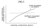
- a method of controlling radio communications and a radio base station using the conventional downlink transmit diversity may degrade the transmission quality characteristics more than without using the downlink transmit diversity, as shown in FIG. 3.
- An object of the present invention is to provide a radio base station and a method of controlling radio communications which prevent degradation of transmission quality characteristics even when there are time differences between the instant of channel estimation of uplink time slots and the instant of transmission of transmission data via downlink time slots.
- a radio base station which comprises: a transmit diversity controller configured to control transmit diversity to be used for each downlink time slot; and a data transmitter configured to transmit data via the downlink time slot using the controlled transmit diversity.
- the radio base station preferably further comprises a channel estimator configured to perform channel estimation of uplink time slots.
- the transmit diversity controller preferably controls the transmit diversity based on the channel estimation.
- the transmit diversity controller preferably controls transmit diversity to be used for each downlink time slot based on the time difference from the instant of the channel estimation.
- the transmit diversity controller preferably determines whether or not to use transmit diversity for each downlink time slot, based on the channel estimation.
- the transmit diversity controller preferably determines a kind of transmit diversity to be used for each downlink time slot, based on the channel estimation.
- a method of controlling radio communications which comprises the steps of: a) controlling, at a radio base station, transmit diversity to be used for each downlink time slot; and b) transmitting, at the radio base station, data in the downlink time slot using the controlled transmit diversity.
- the method preferably further comprises the step of c) performing channel estimation of uplink time slots.
- the transmit diversity is preferably controlled based on the channel estimation.
- the transmit diversity is preferably controlled for each downlink time slot, based on the time difference from the instant of the channel estimation.
- step a) it is preferably determined whether or not to use transmit diversity for each downlink time slot, based on the channel estimation.
- a kind of transmit diversity to be used is preferably determined for each downlink time slot, based on the channel estimation.
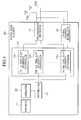
- FIG. 4 is a diagram illustrating the general configuration of a radio base station 10 according to this embodiment.
- the radio base station 10 of this embodiment transmits transmission data to radio information terminals via radio communications channels.
- the radio base station 10 includes, as shown in FIG. 4, an encoder 11, a spreader 12, a distributor 13, a downlink (DL) time slot diversity controller 14, a transmission processor 15, and an uplink channel estimator 16.
- the encoder 11 and the spreader 12 have the same functions as those of the encoder 51 and the spreader 52 of the conventional radio base station 50.
- the encoder 11 is connected to the spreader 12.
- the spreader 12 is connected to the encoder 11 and the distributor 13.
- the distributor 13 is connected to the spreader 12 and the downlink time slot diversity controller 14, dividing transmission data received from the spreader 12 into downlink (DL) time slots (DL#1 to DL#N) and transmitting the respective divided transmission data of the time slots (DL#1 to DL#N) to corresponding downlink (DL) first to Nth time slot diversity controllers 14 1 to 14 N .
- the downlink time slot diversity controller 14 is connected to the distributor 13, the transmission processor 15 and the uplink channel estimator 16, including the downlink first to Nth time slot diversity controllers 14 1 to 14 N corresponding to the downlink time slots (DL#1 to DL#N).
- the downlink first to Nth time slot diversity controllers 14 1 to 14 N determine whether or not to use transmit diversity or determine which transmit diversity to use (a kind of transmit diversity) for the corresponding downlink time slots (DL#1 to DL#N), based on the channel estimation of uplink channels performed by the uplink channel estimator 16, thereby performing diversity control.
- the transmit diversity to be used here includes, for example, downlink transmit diversity (such as STD and TxAA).
- the downlink first to Nth time slot diversity controllers 14 1 to 14 N constitute a transmit diversity controller for controlling transmit diversity to be used for each of the downlink time slots DL#1 to DL#N.
- the downlink third and fourth time slot diversity controllers 14 3 and 14 4 may determine the use of transmit diversity for DL#3 and DL#4, and the downlink fifth to fifteenth time slot diversity controllers 14 5 to 14 15 may determine nonuse of transmit diversity for DL#5 to DL#15.
- the downlink third to fifth time slot diversity controllers 14 3 to 14 5 may determine the use of TxAA for DL#3 to DL#5
- the downlink sixth to fifteenth time slot diversity controllers 14 6 to 14 15 may determine the use of STD for DL#6 to DL#15.
- the transmission processor 15 is connected to the downlink time slot diversity controller 14 and the uplink channel estimator 16, processing transmission data received from the downlink time slot diversity controller 14 in accordance with the corresponding transmit diversity (e.g., selecting a transmission line or weighting each transmission line), performing filtering as required, and transmitting the processed transmission data via antennas 15 a1 and/or 15 a2 .
- the transmission processor 15 constitutes a data transmitter for transmitting data with the downlink time slots DL#1 to DL#N, using controlled transmit diversity.
- the uplink channel estimator 16 is connected to the downlink time slot diversity controller 14 and the antenna 15 a1 and 15 a2 , monitoring uplink radio communications channels set for the antenna 15 a1 and 15 a2 , estimating the status of the uplink radio communications channels (such as waveform distortion, delay fluctuation, amplitude fluctuation, and phase log) (performing channel estimation), and transmitting the channel estimation to the downlink time slot diversity controller 14.
- the uplink channel estimator 16 constitutes a channel estimator for performing channel estimation of uplink time slots UL#1 to UL#N.
- FIG. 5 is a flowchart illustrating the operation of the radio base station 10 for transmitting received transmission data via radio communications channels.
- transmission data to be transmitted via radio communications channels is supplied to the encoder 11.
- the encoder 11 encodes and interleaves the supplied transmission data and transmits the transmission data to the spreader 12.
- the spreader 12 spreads and scrambles the transmission data and transmits the transmission data to the distributor 13.
- the distributor 13 divides the transmission data received from the spreader 12 into down link time slots (DL#1 to DL#N) and transmits the respective divided transmission data of the time slots (DL#1 to DL#N) to the corresponding downlink first to Nth time slot diversity controllers 14 1 to 14 N .
- the downlink first to Nth time slot diversity controllers 14 1 and 14 N determine whether or not to use transmit diversity for the corresponding downlink time slots (DL#1 to DL#N) or determine which transmit diversity to use, based on the channel estimation of the uplink channels performed by the uplink channel estimator 16, thereby performing diversity control.
- the transmission processor 15 processes the transmission data received from the downlink time slot diversity controller 14 in accordance with the corresponding transmit diversity (e.g., selects a transmission line or weights each transmission line), performs filtering as required, and transmits the processed transmission data via the antennas 15 a1 and 15 a2 .
- the radio base station 10 has the downlink first to Nth time slot diversity controllers 14 1 and 14 2 which control transmit diversity to be used for the respective downlink time slots (DL#1 to DL#N), thus preventing degradation of downlink transmission quality characteristics even when there is a time difference between the instant of the channel estimation of an uplink time slot (UL#2) and the instant of transmission of transmission data via a downlink time slot (UL#15).
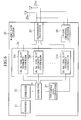
- the present invention is not limited to the above embodiment, and may have a threshold data comparator provided between a distributor 23 and a downlink time slot diversity controller 24 as shown in FIG. 6.
- the threshold data comparator 27 measures time differences between downlink time slots (DL#1 to DL#N) with data divided by the distributor 23 therefor and a time slot on which channel estimation is performed, and compares the time differences found by the measurements with a time difference as predetermined threshold data.
- the threshold data comparator 27 transmits the comparison results to corresponding downlink first to Nth time slot diversity controllers 24 1 to 24 N .
- the downlink first to Nth time slot diversity controllers 24 1 to 24 N determine whether or not to use transmit diversity for the corresponding downlink time slots (DL#1 to DL#N) or determine which transmit diversity to use, based on the channel estimation of the uplink channels by an uplink channel estimator 26 and the comparison results received from the threshold data comparator 27, thereby performing diversity control.
- Transmit diversity to be used here includes downlink transmit diversity (such as STD and TxAA), for example.
- the downlink first to Nth time slot diversity controllers 24 1 to 24 N constitute a transmit diversity controller for controlling transmit diversity to be used for each of the downlink time slots DL#1 to DL#N.
- the downlink third to sixth time slot diversity controllers 24 3 to 24 6 may determine use of transmit diversity for DL#3 to DL#6 which are time slots not exceeding a time difference as predetermined threshold data (e.g., four time slots), and the seventh to fifteenth time slot diversity controllers 24 7 to 24 15 may determine nonuse of transmit diversity for DL#7 to DL#15 which are time slots exceeding the time difference as the predetermined threshold data (e.g., four time slots).
- predetermined threshold data e.g., four time slots
- the downlink third to sixth time slot diversity controllers 24 3 to 24 6 may determine use of TxAA for DL#3 to DL#6 which are time slots not exceeding a time difference as predetermined threshold data (e.g., four time slots), and the seventh to fifteenth time slot diversity controllers 24 7 to 24 15 may determine use of STD for DL#7 to DL#15 which are time slots exceeding the time difference as the predetermined threshold data (e.g., four time slots).
- predetermined threshold data e.g., four time slots
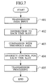
- FIG. 7 is a flowchart illustrating the operation of the radio base station 20 for transmitting received transmission data via radio communications channels.
- transmission data to be transmitted via radio communications channels is supplied to an encoder 21.
- the encoder 21 encodes and interleaves the supplied transmission data and transmits the transmission data to a spreader 22.
- the spreader 22 spreads and scrambles the transmission data and transmits the transmission data to the distributor 23.
- the distributor 23 divides the transmission data received from the spreader 12 into the downlink time slots (DL#1 to DL#N) and transmits the respective divided transmission data of the time slots (DL#1 to DL#N) to the corresponding downlink first to Nth time slot diversity controllers 24 1 to 24 N .
- the threshold data comparator 27 measures time differences between the downlink time slots (DL#1 to DL#N) with the data divided by the distributor 23 therefor and a time slot on which channel estimation is performed, and compares the time differences found by the measurements and a time difference as predetermined threshold data.
- the threshold data comparator 27 transmits the comparison results to the corresponding downlink first to Nth time slot diversity controllers 24 1 to 24 N .
- the downlink first to Nth time slot diversity controllers 24 1 to 24 N determine whether or not to use transmit diversity or determines which transmit diversity to use for the corresponding downlink time slots (DL#1 to DL#N), based on the channel estimation of uplink channels performed by the uplink channel estimator 26 and the comparison results received from the threshold data comparator 27, thereby performing diversity control.
- a transmission processor 25 processes the transmission data received from the downlink time slot diversity controller 24 in accordance with the corresponding transmit diversity (e.g., selects a transmission line or weights each transmission line), performs filtering as required, and transmits the processed transmission data via antennas 25 a1 and 25 a2 .
- the present invention may be applied not only to TDMA and TDD systems (that is, systems using time slots as radio communications channels) as in the above embodiment and modification 1, but also to CDMA-TDD systems (that is, systems using spread codes as radio communications channels).
- the present invention can provide a radio base station and a method of controlling radio communications which prevent degradation of transmission quality characteristics even when there are time differences between the instant of channel estimation of uplink time slots and the instant of transmission of transmission data via downlink time slots.
Landscapes
- Engineering & Computer Science (AREA)
- Computer Networks & Wireless Communication (AREA)
- Signal Processing (AREA)
- Mobile Radio Communication Systems (AREA)
- Radio Transmission System (AREA)
- Time-Division Multiplex Systems (AREA)
Abstract
Description
Claims (6)
- A radio base station comprising:a channel estimator configured to perform channel estimation of an uplink time slot;a transmit diversity controller configured to control transmit diversity to be used for each downlink time slot, based on said channel estimation and the time difference from the instant of said channel estimation; anda data transmitter configured to transmit data in said downlink time slot using said controlled transmit diversity.
- A radio base station as set forth in claim 1, wherein:said transmit diversity controller determines whether or not to use transmit diversity for each downlink time slot, based on said channel estimation and the time difference from the instant of said channel estimation.
- A radio base station as set forth in claim 1, wherein:said transmit diversity controller determines a kind of transmit diversity to be used for each downlink time slot, based on said channel estimation and the time difference from the instant of said channel estimation.
- A method of controlling radio communications, comprising the steps of:a) performing, at a radio base station, channel estimation of an uplink time slot;b) controlling, at said radio base station, transmit diversity to be used for each downlink time slot, based on said channel estimation and the time difference from the instant of said channel estimation; andc) transmitting, at said radio base station, data in said downlink time slot using said controlled transmit diversity.
- A method of controlling radio communications as set forth in claim 4, wherein:in said step b), it is determined whether or not to use transmit diversity for each downlink time slot, based on said channel estimation and the time difference from the instant of said channel estimation.
- A method of controlling radio communications as set forth in claim 4, wherein:in said step b), a kind of transmit diversity to be used is determined for each downlink time slot, based on said channel estimation and the time difference from the instant of said channel estimation.
Applications Claiming Priority (2)
| Application Number | Priority Date | Filing Date | Title |
|---|---|---|---|
| JP2001270870 | 2001-09-06 | ||
| JP2001270870A JP2003087161A (en) | 2001-09-06 | 2001-09-06 | Radio base station and radio communication control method |
Publications (3)
| Publication Number | Publication Date |
|---|---|
| EP1292049A2 true EP1292049A2 (en) | 2003-03-12 |
| EP1292049A3 EP1292049A3 (en) | 2003-07-02 |
| EP1292049B1 EP1292049B1 (en) | 2005-04-27 |
Family
ID=19096469
Family Applications (1)
| Application Number | Title | Priority Date | Filing Date |
|---|---|---|---|
| EP20020019758 Expired - Lifetime EP1292049B1 (en) | 2001-09-06 | 2002-09-04 | Radio base station and method of controlling radio communications with transmit diversity |
Country Status (5)
| Country | Link |
|---|---|
| US (1) | US7502359B2 (en) |
| EP (1) | EP1292049B1 (en) |
| JP (1) | JP2003087161A (en) |
| CN (1) | CN1190098C (en) |
| DE (1) | DE60203859T2 (en) |
Cited By (2)
| Publication number | Priority date | Publication date | Assignee | Title |
|---|---|---|---|---|
| US7400692B2 (en) | 2004-01-14 | 2008-07-15 | Interdigital Technology Corporation | Telescoping window based equalization |
| US7437135B2 (en) | 2003-10-30 | 2008-10-14 | Interdigital Technology Corporation | Joint channel equalizer interference canceller advanced receiver |
Families Citing this family (6)
| Publication number | Priority date | Publication date | Assignee | Title |
|---|---|---|---|---|
| JP3975069B2 (en) * | 2001-10-25 | 2007-09-12 | 株式会社エヌ・ティ・ティ・ドコモ | Radio base station and radio communication control method |
| GB2394144B (en) * | 2002-10-10 | 2005-01-26 | Motorola Inc | Regulation of time intervals in a wireless communication system |
| JP4050644B2 (en) * | 2003-03-27 | 2008-02-20 | 株式会社日本製鋼所 | Inline screw plasticizing injection device |
| US7313126B2 (en) * | 2003-07-31 | 2007-12-25 | Samsung Electronics Co., Ltd. | Control system and multiple access method in wireless communication system |
| US7564814B2 (en) * | 2004-05-07 | 2009-07-21 | Qualcomm, Incorporated | Transmission mode and rate selection for a wireless communication system |
| CN116709552A (en) * | 2022-12-13 | 2023-09-05 | 南京埃尔乔亿自控设备有限公司 | Intelligent micro base station fusion wireless communication system |
Family Cites Families (11)
| Publication number | Priority date | Publication date | Assignee | Title |
|---|---|---|---|---|
| DE19543622C2 (en) * | 1995-11-23 | 1999-12-30 | Deutsche Telekom Ag | Method and device for the bidirectional transmission of high-rate digital signals |
| US5991282A (en) * | 1997-05-28 | 1999-11-23 | Telefonaktiebolaget Lm Ericsson | Radio communication system with diversity reception on a time-slot by time-slot basis |
| JP3981475B2 (en) | 1998-01-26 | 2007-09-26 | 松下電器産業株式会社 | COMMUNICATION TERMINAL DEVICE, BASE STATION COMMUNICATION DEVICE, AND RADIO COMMUNICATION SYSTEM |
| JP3798549B2 (en) | 1998-03-18 | 2006-07-19 | 富士通株式会社 | Multi-beam antenna system for radio base station |
| AU5681099A (en) * | 1998-08-25 | 2000-03-14 | Ericsson Inc. | Wireless communications system employing selective diversity transmission, method for selectively enabling diversity transmission, and a wireless telecommunications network employing the system or the method |
| DE19850279B4 (en) * | 1998-10-30 | 2005-12-22 | Robert Bosch Gmbh | Method for the transmission of signals between a first radio station and a second radio station and radio station |
| KR100555986B1 (en) | 1999-05-19 | 2006-03-03 | 노키아 네트워크즈 오와이 | Transmission Diversity Method and System |
| US6151487A (en) * | 1999-08-31 | 2000-11-21 | Hughes Electronics Corporation | Demodulation structure for fast fading cellular channels |
| FI107671B (en) | 1999-10-08 | 2001-09-14 | Nokia Mobile Phones Ltd | Procedure and arrangement for timing the change of diversity coefficients in a cellular radio system |
| JP3663092B2 (en) | 1999-11-19 | 2005-06-22 | 三洋電機株式会社 | Wireless base station |
| DE10009150A1 (en) * | 2000-02-26 | 2001-08-30 | Bosch Gmbh Robert | Data transmission method and system |
-
2001
- 2001-09-06 JP JP2001270870A patent/JP2003087161A/en active Pending
-
2002
- 2002-09-04 EP EP20020019758 patent/EP1292049B1/en not_active Expired - Lifetime
- 2002-09-04 DE DE2002603859 patent/DE60203859T2/en not_active Expired - Lifetime
- 2002-09-06 CN CNB021416265A patent/CN1190098C/en not_active Expired - Fee Related
- 2002-09-06 US US10/235,707 patent/US7502359B2/en not_active Expired - Fee Related
Cited By (2)
| Publication number | Priority date | Publication date | Assignee | Title |
|---|---|---|---|---|
| US7437135B2 (en) | 2003-10-30 | 2008-10-14 | Interdigital Technology Corporation | Joint channel equalizer interference canceller advanced receiver |
| US7400692B2 (en) | 2004-01-14 | 2008-07-15 | Interdigital Technology Corporation | Telescoping window based equalization |
Also Published As
| Publication number | Publication date |
|---|---|
| JP2003087161A (en) | 2003-03-20 |
| US20030043770A1 (en) | 2003-03-06 |
| CN1190098C (en) | 2005-02-16 |
| EP1292049A3 (en) | 2003-07-02 |
| DE60203859T2 (en) | 2006-02-23 |
| EP1292049B1 (en) | 2005-04-27 |
| DE60203859D1 (en) | 2005-06-02 |
| CN1404336A (en) | 2003-03-19 |
| US7502359B2 (en) | 2009-03-10 |
Similar Documents
| Publication | Publication Date | Title |
|---|---|---|
| US10673509B2 (en) | Efficient CQI signaling in multi-beam MIMO systems | |
| US5444696A (en) | Frame structure using consecutive slot assignments for mobile communications | |
| EP1886419B1 (en) | Apparatus and method for transmitting/receiving data in a mobile communication system using multiple antennas | |
| FI105368B (en) | Power control in mobile communication system | |
| JP4105133B2 (en) | Scheduling method and apparatus for multiple users in a mobile communication system using multiple transmit / receive antennas | |
| US7304939B2 (en) | Communication using simultaneous orthogonal signals | |
| EP1185120A1 (en) | Base station apparatus and handover control method | |
| US8339977B2 (en) | Method and apparatus for allocation of parameters for radio transmission in wireless communication network | |
| US7342943B2 (en) | Radio base station and method of controlling radio communications | |
| US7688979B2 (en) | MIMO air interface utilizing dirty paper coding | |
| US10412686B2 (en) | Radio communication system, method of operating a communication system, and a mobile station | |
| US7502359B2 (en) | Radio base station and method of controlling radio communications | |
| US6396821B1 (en) | Radio communication apparatus of diversity transmission system | |
| EP0951759B1 (en) | Transmission method and radio system | |
| US8064538B2 (en) | Communication device and communication method | |
| US20060035608A1 (en) | Method and system for using angular hopping in wireless communication systems | |
| US20030083017A1 (en) | Telecommunication system with improved downlink quality feedback | |
| US20050084027A1 (en) | Method for multiple broadcasting in a mobile radiocommunication system | |
| CN1303544A (en) | Method and radio station for signal transmission in radio communication system | |
| HK1034618A (en) | Method and radio station for transmitting data |
Legal Events
| Date | Code | Title | Description |
|---|---|---|---|
| PUAI | Public reference made under article 153(3) epc to a published international application that has entered the european phase |
Free format text: ORIGINAL CODE: 0009012 |
|
| 17P | Request for examination filed |
Effective date: 20020904 |
|
| AK | Designated contracting states |
Kind code of ref document: A2 Designated state(s): AT BE BG CH CY CZ DE DK EE ES FI FR GB GR IE IT LI LU MC NL PT SE SK TR |
|
| AX | Request for extension of the european patent |
Extension state: AL LT LV MK RO SI |
|
| PUAL | Search report despatched |
Free format text: ORIGINAL CODE: 0009013 |
|
| AK | Designated contracting states |
Designated state(s): AT BE BG CH CY CZ DE DK EE ES FI FR GB GR IE IT LI LU MC NL PT SE SK TR |
|
| AX | Request for extension of the european patent |
Extension state: AL LT LV MK RO SI |
|
| 17Q | First examination report despatched |
Effective date: 20031006 |
|
| AKX | Designation fees paid |
Designated state(s): DE GB |
|
| GRAP | Despatch of communication of intention to grant a patent |
Free format text: ORIGINAL CODE: EPIDOSNIGR1 |
|
| RIN1 | Information on inventor provided before grant (corrected) |
Inventor name: MOON, SUNG UK,INT. PROP. DEPT.,NTT DOCOMO, INC. Inventor name: FUTAKATA, TOSHIYUKI,INT.PROP.DPT.,NTT DOCOMO INC |
|
| GRAS | Grant fee paid |
Free format text: ORIGINAL CODE: EPIDOSNIGR3 |
|
| GRAA | (expected) grant |
Free format text: ORIGINAL CODE: 0009210 |
|
| AK | Designated contracting states |
Kind code of ref document: B1 Designated state(s): DE GB |
|
| REG | Reference to a national code |
Ref country code: GB Ref legal event code: FG4D |
|
| REF | Corresponds to: |
Ref document number: 60203859 Country of ref document: DE Date of ref document: 20050602 Kind code of ref document: P |
|
| PLBE | No opposition filed within time limit |
Free format text: ORIGINAL CODE: 0009261 |
|
| STAA | Information on the status of an ep patent application or granted ep patent |
Free format text: STATUS: NO OPPOSITION FILED WITHIN TIME LIMIT |
|
| 26N | No opposition filed |
Effective date: 20060130 |
|
| PGFP | Annual fee paid to national office [announced via postgrant information from national office to epo] |
Ref country code: GB Payment date: 20120829 Year of fee payment: 11 |
|
| PGFP | Annual fee paid to national office [announced via postgrant information from national office to epo] |
Ref country code: DE Payment date: 20120829 Year of fee payment: 11 |
|
| GBPC | Gb: european patent ceased through non-payment of renewal fee |
Effective date: 20130904 |
|
| REG | Reference to a national code |
Ref country code: DE Ref legal event code: R119 Ref document number: 60203859 Country of ref document: DE Effective date: 20140401 |
|
| PG25 | Lapsed in a contracting state [announced via postgrant information from national office to epo] |
Ref country code: GB Free format text: LAPSE BECAUSE OF NON-PAYMENT OF DUE FEES Effective date: 20130904 |
|
| PG25 | Lapsed in a contracting state [announced via postgrant information from national office to epo] |
Ref country code: DE Free format text: LAPSE BECAUSE OF NON-PAYMENT OF DUE FEES Effective date: 20140401 |
|
| P01 | Opt-out of the competence of the unified patent court (upc) registered |
Effective date: 20230520 |