EP1292046A2 - Method, wireless network system and base station thereof for controlling power and interference - Google Patents
Method, wireless network system and base station thereof for controlling power and interference Download PDFInfo
- Publication number
- EP1292046A2 EP1292046A2 EP02016776A EP02016776A EP1292046A2 EP 1292046 A2 EP1292046 A2 EP 1292046A2 EP 02016776 A EP02016776 A EP 02016776A EP 02016776 A EP02016776 A EP 02016776A EP 1292046 A2 EP1292046 A2 EP 1292046A2
- Authority
- EP
- European Patent Office
- Prior art keywords
- base station
- interference
- power
- traffic
- interfered
- Prior art date
- Legal status (The legal status is an assumption and is not a legal conclusion. Google has not performed a legal analysis and makes no representation as to the accuracy of the status listed.)
- Granted
Links
- 238000000034 method Methods 0.000 title claims description 18
- 230000004044 response Effects 0.000 claims abstract description 14
- 230000007423 decrease Effects 0.000 claims description 6
- 238000012544 monitoring process Methods 0.000 claims description 6
- 238000001514 detection method Methods 0.000 claims description 4
- 230000008569 process Effects 0.000 description 7
- 238000004891 communication Methods 0.000 description 3
- 230000009467 reduction Effects 0.000 description 3
- 230000005540 biological transmission Effects 0.000 description 2
- 238000007796 conventional method Methods 0.000 description 2
- 230000003247 decreasing effect Effects 0.000 description 2
- 238000001914 filtration Methods 0.000 description 2
- 101100172132 Mus musculus Eif3a gene Proteins 0.000 description 1
- 230000001413 cellular effect Effects 0.000 description 1
- 230000008859 change Effects 0.000 description 1
- 238000010586 diagram Methods 0.000 description 1
- 239000000284 extract Substances 0.000 description 1
- 238000009434 installation Methods 0.000 description 1
- 230000007246 mechanism Effects 0.000 description 1
- 238000010295 mobile communication Methods 0.000 description 1
- 230000004043 responsiveness Effects 0.000 description 1
Images





Classifications
-
- H—ELECTRICITY
- H04—ELECTRIC COMMUNICATION TECHNIQUE
- H04W—WIRELESS COMMUNICATION NETWORKS
- H04W52/00—Power management, e.g. Transmission Power Control [TPC] or power classes
- H04W52/04—Transmission power control [TPC]
- H04W52/18—TPC being performed according to specific parameters
- H04W52/24—TPC being performed according to specific parameters using SIR [Signal to Interference Ratio] or other wireless path parameters
-
- H—ELECTRICITY
- H04—ELECTRIC COMMUNICATION TECHNIQUE
- H04W—WIRELESS COMMUNICATION NETWORKS
- H04W52/00—Power management, e.g. Transmission Power Control [TPC] or power classes
- H04W52/04—Transmission power control [TPC]
- H04W52/18—TPC being performed according to specific parameters
- H04W52/24—TPC being performed according to specific parameters using SIR [Signal to Interference Ratio] or other wireless path parameters
- H04W52/243—TPC being performed according to specific parameters using SIR [Signal to Interference Ratio] or other wireless path parameters taking into account interferences
- H04W52/244—Interferences in heterogeneous networks, e.g. among macro and femto or pico cells or other sector / system interference [OSI]
-
- H—ELECTRICITY
- H04—ELECTRIC COMMUNICATION TECHNIQUE
- H04W—WIRELESS COMMUNICATION NETWORKS
- H04W52/00—Power management, e.g. Transmission Power Control [TPC] or power classes
- H04W52/04—Transmission power control [TPC]
- H04W52/06—TPC algorithms
- H04W52/14—Separate analysis of uplink or downlink
- H04W52/143—Downlink power control
-
- H—ELECTRICITY
- H04—ELECTRIC COMMUNICATION TECHNIQUE
- H04W—WIRELESS COMMUNICATION NETWORKS
- H04W84/00—Network topologies
- H04W84/02—Hierarchically pre-organised networks, e.g. paging networks, cellular networks, WLAN [Wireless Local Area Network] or WLL [Wireless Local Loop]
- H04W84/10—Small scale networks; Flat hierarchical networks
- H04W84/12—WLAN [Wireless Local Area Networks]
-
- H—ELECTRICITY
- H04—ELECTRIC COMMUNICATION TECHNIQUE
- H04W—WIRELESS COMMUNICATION NETWORKS
- H04W88/00—Devices specially adapted for wireless communication networks, e.g. terminals, base stations or access point devices
- H04W88/08—Access point devices
Definitions
- This invention relates to a wireless local area network (LAN) adopting CSMA/CA (Carrier Sense Multiple Access with Collision Avoidance), and particularly, relates to connection control for avoiding channel interference between base stations (BS) of a wireless LAN.
- LAN wireless local area network
- CA Carrier Sense Multiple Access with Collision Avoidance
- a wireless LAN is a LAN in which terminals such as personal computers communicate with base stations by radio signals.
- a wireless LAN has the advantages over a LAN in which terminals are connected with the LAN by cables.
- a wireless LAN does not require cables for connecting terminals. Wiring works are unnecessary when the terminals are rearranged. Consequently, a wireless LAN can cut expenses for changing layout in an office.
- notebook computers connected via radio waves with a wireless LAN can immediately establish same circumstance anywhere in the service area of the wireless LAN. For example, when a business presentation is held in a reception room and an electronic data file is suddenly needed, if such notebook computer is brought into the room, then the file may be accessed via the wireless LAN without delay.
- a wireless LAN including notebook computers is available for holding a paperless meeting and for cooperating to discuss and edit same documents with each other. Consequently, notebook computers connected with each other via a wireless LAN can accelerate efficiency, mobility and responsiveness of business.
- base stations are added in order to increase wireless terminals accommodated in the LANs or to extend the service areas of the LANs. Furthermore, base stations may be sometimes rearranged in the location in which the wireless LAN is installed. When a base station is added to a wireless LAN, or rearranged in a wireless LAN, interference of radio waves may occur. In order to avoid interference and to maximize a service area of a wireless LAN, the base stations in the wireless LAN has to be adjusted properly. On the other hand, the users of a LAN themselves usually introduce or add a base station to the LAN. Therefore, base stations are hopefully adjusted automatically, without adjustment by the users.
- wireless LAN systems are required to satisfy specifications almost the same as wired LAN systems do. Such specifications are for example a few hundred kbps to 20 Mbps transmission speed, several ten meters radius transmission range, 8 to 10 bit error rate (BER), and connectability with wired LAN system. A technique for avoiding interference in a wireless LAN is also required to satisfy the specifications. Both expense and technical requirement for installing a wireless LAN are hopefully low.
- This invention provides a method, a wireless network and a base station of the wireless network for controlling power to send radio waves from a base station of a wireless network.
- a wireless network system of the invention one base station autonomously and individually establishes channel without interference with another base station.
- the wireless network system of the invention can avoid channel interference between the base stations of the system with simple and easy mechanism.
- a network system includes at least two base stations for establishing wireless connection to wireless terminals.
- the base stations are connected via at least one cable with each other.
- the interfered base station informs the source base station of the occurrence of the interference via the cable.
- the source base station controls its power to send radio waves in response to the information.
- the source base station may repeatedly decrease the power by a predetermined amount until the interfered base station loses the detection of the interference.
- the source base station may monitor traffic of the interfered base station via the cable and recover the power if the traffic falls short of a predetermined threshold.
- the source base station may monitor traffic of the interfered base station and fix the controlled power if the traffic keeps exceeding a predetermined threshold.
- a method of controlling power to send radio waves from a base station for establishing wireless connection between a network and a wireless terminal includes at least two base stations.
- the base stations are connected with each other via at least one cable.
- the interfered base station informs the source base station of the occurrence of the interference via the cable.
- the source base station controls its power to send radio waves in response to the information.
- a base station including a wireless interface circuit for establishing wireless connection with a wireless terminal and wired interface circuit for establishing wired connection with another base station.
- This base station includes the circuits for: detecting interference with a first base station; generating interference information for informing the first base station of occurrence of interference to send the interference information to the first base station via the wired interface circuit; detecting interference information which is generated by a second base station and is received via the wired interface circuit; and controlling power to send radio waves in response to the interference information generated by the second base station.
- wireless communication is done through one channel (radio frequency) in one radio cell, and two base stations adjacent to each other use same channel to send radio waves.
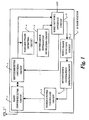
- a base station 10 includes an antenna 1 and a radio sender/receiver circuit 2 as interface for wireless communication.
- the radio sender/receiver circuit 2 converts the radio waves to base band signals and sends the base band signals to a sender/receiver switching circuit 3.
- the sender/receiver switching circuit 3 distributes up signals, which are conveyed from wireless terminals or other base stations to the base station 10, to a wireless frame detecting circuit 4 and a wired network interface circuit 6, and on the other hand, distributes down signals, which are conveyed from the base station 10 to wireless terminals, to the sender part of the radio sender/receiver circuit 2.
- the wired network interface circuit 6 is connected with a local area network (LAN) via a cable in order to communicate with terminals or other base stations via the LAN.
- LAN local area network
- the wireless frame detecting circuit 4 and the wired frame detecting circuit 7 detect frames in base band signals and outputs the frames.
- the interference information generating circuit 5 judges whether or not the base station 10 is interfered with another base station and outputs interference information if the base station 10 is interfered.
- the interference information detecting circuit 8 detects a frame containing the interference information and informs the sending power controller circuit 9 of detecting the frame.
- the interference information generating circuit 5 detects interference and identifies its source base station. Next, the interference information generating circuit 5 generates a frame containing interference information and'sends the frame to the source base station via the wired network interface circuit 6 and the LAN.
- the interference information detecting circuit 8 receives the frame via the wired network interface circuit 6 and the wired frame detecting circuit 7, and detects the interference information contained in the frame. Next, the interference information detecting circuit 8 extracts the interference information and sends it to a sending power controller circuit 9. According to the interference information, the sending power controller circuit 9 instructs the radio sender/receiver circuit 2 to adjust the power to send radio waves in order to avoid interference with the other base station.
- a wireless LAN system including two base stations 21 and 22, each of which corresponds to the base station 10.
- the base stations 21 and 22 are connected with a network 20.
- the base station 21 has a service area 23 which expresses one area in which radio waves from the base station 21 can be received.
- the base station 22 has a service area 24 which expresses another area in which radio waves from the base station 22 can be received.
- a wall 25 stands between the base stations 21 and 22 and blocks radio waves from both of the stations 21 and 22. In the state shown in Fig. 2, there is no interference between the base stations 21 and 22.
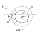
- the wall 25 has been removed, and as a result, the base station 21 is covered with the service area 24. Consequently, the base station 21 is now interfered with the base station 22.
- the base station 21 detects the interference and sends an interference information to the base station 22 via the network 20.
- the base station 22 receives the interference information from the base station 21 via the network 20.
- the base station 22 reduces the power to send radio waves in order to stop the interference.
- the service area of the base station 22 is reduced from the service area 24 to a service area 26, which does not cover the base station 21.
- the base station 22 While the service area 24 is reduced to the service area 26, the base station 22 activates a process for monitoring the traffic of the base station 21. As shown in Fig. 5, the base station 22 monitors the traffic of the base station 21 via the network 20. The traffic monitoring process compares the traffic with a predetermined threshold.
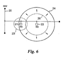
- the declination of the traffic means that the base station 21 requires only low bandwidth to establish wireless connections. In this situation, even if the base station 22 interferes with the base station 21, the base station 21 can establish wireless connections. Taking this into consideration, if the traffic becomes under the threshold, then the base station 22 recovers its service area from the service area 26 to the service area 24 as shown in Fig. 6.
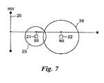
- the base station 22 keeps the service area 26 as shown in Fig. 7.
- the base stations 21 and 22 initialize powers to send radio waves (STEP 100).
- the base stations 21 and 22 check whether or not interference occurs (STEPS 101 and 102). If no interference occurs, then the process ends.
- the base stations 21 and 22 sense carrier at regular intervals to avoid collision and send beacon frames on radio waves to communicate wireless terminals in their service areas. Furthermore, the base stations 21 and 22 receives radio signals from not only wireless terminals but also other base stations. When the base stations 21 and 22 receives radio waves from other base stations, the base stations 21 and 22 demodulate the radio waves by the sender/receiver switching circuit 3 and filter the demodulated signals by the wireless frame detecting circuit 4 to detect beacon frames from other base stations.
- Each of wireless terminals has a MAC (Media Access Control) address which is defined as a unique physical address in the data link layer of the OSI reference model for controlling access to a network device.
- MAC Media Access Control
- the interference detection is done at both base stations 21 and 22. If both of them do not detect interference from the other base station, it is unnecessary to change the powers to send radio waves of the base stations 21 and 22. Consequently, the wireless LAN ends the sending power control process (STEP 102).
- Interference occurs when the surroundings of the wireless LAN or the wireless LAN itself has changed. Now it is assumed that the base station 21 has detected interference from the base station 22. In the base station 21, when the interference information generating circuit 5 detects interference and generates interference information (STEP 103), and sends the interference information via the wired network interface circuit 6 and the wired network 20 to the base station 22 (STEP 104).
- the interference information detecting circuit 8 receives the interference information from the base station 21 via the wired network 20, the wired network interface circuit 6 and the wired frame detecting circuit 7.
- the circuit 8 gives a notice to the sending power controller circuit 9.
- the sending power controller circuit 9 makes the radio sender/receiver circuit 2 decrease the power to send radio waves by a predetermined amount (STEP 105).
- the sending power from the base station 22 is determined (STEP 107).
- the service area of the base station 22 is reduced from the service area 24 to 26 as shown in Fig. 4. This reduction of the service area may cause disconnection between the wireless LAN system and some of its wireless terminals.
- the base station 22 monitors traffic of the base station 21 via the wired network 22 and judges whether or not the power can be recovered from the reduced power at STEP 107 to the initial power at STEP 100.
- the base station 22 monitors the traffic of the base station 21 through the LAN (STEP 108), and compares the traffic with a predetermined threshold (STEP 109).
- the sending power of the base station 22 is recovered to the initial power (STEP 110).
- the comparison between the monitored traffic and the threshold is repeated a predetermined times (STEPS 111 and 112). If the traffic remains exceeding the threshold after finishing the repeat, then the sending power of the base station 22 is fixed at the power determined at STEP 107 and the sending power control process is finished.
- a base station which is interfered with another base station, sends interference information to the source base station via a wired network.
- the source base station decreases its power to send radio waves so as to exclude the interfered base station from the service area of the source base station.
- the source base station monitors traffic of the interfered base station. If the traffic falls short of a threshold, then the source base station recovers its power to the initial one.
- the present invention can reduce the cost of installing an additional base station in a wireless LAN. No operation is required to users who intend to install a new base station even if channel interference occurs between an existing and a new base stations.
- the wireless LAN includes two base stations; a wall initially stands between the base stations; and interference between the base stations occurs after the wall is removed.
- the present invention can however be put into other manners. For example, the number of base station or the reason why interference occurs can be changed in the scope of the present invention. Interference may be caused by installation of an additional base station or other unexpected reason.
- the power to send radio waves is decreased step by step in response to interference information.
- the base station may further include circuits for measuring strength of interference.
- the interference information generating circuit 5 generates interference information including the strength and the sending power controller circuit 9 controls the power in response to the strength.
Landscapes
- Engineering & Computer Science (AREA)
- Computer Networks & Wireless Communication (AREA)
- Signal Processing (AREA)
- Mobile Radio Communication Systems (AREA)
- Small-Scale Networks (AREA)
Abstract
Description
Claims (12)
- A network system comprising at least two base stations for establishing wireless connection to wireless terminals, the base stations being connected via at least one cable with each other, wherein:when one of the base stations, or an interfered base station detects interference with another one of the base stations, or source base station, the interfered base station informs the source base station of the occurrence of the interference via the cable; andthe source base station controls its power to send radio waves in response to the information.
- The network system claimed in claim 1, wherein the source base station repeatedly decreases the power by a predetermined amount until the interfered base station loses the detection of the interference.
- The network system claimed in claim 1, wherein:the source base station monitors traffic of the interfered base station via the cable; andthe source base station recovers the power if the traffic falls short of a predetermined threshold.
- The network system claimed in claim 1, wherein:the source base station monitors traffic of the interfered base station; andthe source base station fixes the controlled power if the traffic keeps exceeding a predetermined threshold.
- A method of controlling power to send radio waves from a base station for establishing wireless connection between a network and a wireless terminal, the network comprising at least two base stations, the base stations being connected with each other via at least one cable, wherein:when one of the base stations, or an interfered base station detects interference with another one of the base stations, or source base station, the interfered base station informs the source base station of the occurrence of the interference via the cable; andthe source base station controls its power to send radio waves in response to the information.
- The method claimed in claim 5, wherein the source base station repeatedly decreases the power by a predetermined amount until the interfered base station loses the detection of the interference.
- The method claimed in claim 5, wherein:the source base station monitors traffic of the interfered base station via the cable; andthe source base station recovers the power if the traffic falls short of a predetermined threshold.
- The method claimed in claim 5, wherein:the source base station monitors traffic of the interfered base station; andthe source base station fixes the controlled power if the traffic keeps exceeding a predetermined threshold.
- A base station comprising a wireless interface circuit for establishing wireless connection with a wireless terminal and wired interface circuit for establishing wired connection with another base station, comprising the circuits for:detecting interference with a first base station;generating interference information for informing the first base station of occurrence of interference to send the interference information to the first base station via the wired interface circuit;detecting interference information which is generated by a second base station and is received via the wired interface circuit; andcontrolling power to send radio waves in response to the interference information generated by the second base station.
- The base station claimed in claim 9, wherein the controlling circuit repeatedly decreases the power by a predetermined amount until no interference information has been received from the second base station for a predetermined time period.
- The base station claimed in claim 9, further comprising the circuit for monitoring traffic of the second base station via the wired connection, wherein the controlling circuit recovers the power if the traffic falls short of a predetermined threshold.
- The base station claimed in claim 9, further comprising the circuit for monitoring traffic of the second base station, wherein the controlling circuit fixes the power if the traffic keeps exceeding a predetermined threshold.
Applications Claiming Priority (2)
| Application Number | Priority Date | Filing Date | Title |
|---|---|---|---|
| JP2001226121 | 2001-07-26 | ||
| JP2001226121A JP2003037556A (en) | 2001-07-26 | 2001-07-26 | Wireless lan system and its control method |
Publications (3)
| Publication Number | Publication Date |
|---|---|
| EP1292046A2 true EP1292046A2 (en) | 2003-03-12 |
| EP1292046A3 EP1292046A3 (en) | 2003-10-01 |
| EP1292046B1 EP1292046B1 (en) | 2006-04-19 |
Family
ID=19058998
Family Applications (1)
| Application Number | Title | Priority Date | Filing Date |
|---|---|---|---|
| EP02016776A Expired - Lifetime EP1292046B1 (en) | 2001-07-26 | 2002-07-26 | Method, wireless network system and base station thereof for controlling power and interference |
Country Status (4)
| Country | Link |
|---|---|
| US (1) | US20030022692A1 (en) |
| EP (1) | EP1292046B1 (en) |
| JP (1) | JP2003037556A (en) |
| DE (1) | DE60210716D1 (en) |
Families Citing this family (15)
| Publication number | Priority date | Publication date | Assignee | Title |
|---|---|---|---|---|
| US20060171335A1 (en) * | 2005-02-03 | 2006-08-03 | Michael Yuen | Backup channel selection in wireless LANs |
| US7869822B2 (en) * | 2003-02-24 | 2011-01-11 | Autocell Laboratories, Inc. | Wireless network apparatus and system field of the invention |
| WO2004077711A2 (en) | 2003-02-24 | 2004-09-10 | Hawe William R | System, method and apparatus for ascertaining a dynamic attribute of a system |
| US7346021B2 (en) | 2003-08-06 | 2008-03-18 | Matsushita Electric Industrial Co., Ltd. | Master station in communications system and access control method |
| ES2294539T3 (en) | 2003-08-06 | 2008-04-01 | Matsushita Electric Industrial Co., Ltd | MAIN STATION OF COMMUNICATION SYSTEM, AND ACCESS CONTROL METHOD. |
| US20060171304A1 (en) * | 2005-02-03 | 2006-08-03 | Hill David R | WLAN background scanning |
| US20060171305A1 (en) * | 2005-02-03 | 2006-08-03 | Autocell Laboratories, Inc. | Access point channel forecasting for seamless station association transition |
| US8411616B2 (en) | 2005-11-03 | 2013-04-02 | Piccata Fund Limited Liability Company | Pre-scan for wireless channel selection |
| JP2007243505A (en) * | 2006-03-08 | 2007-09-20 | Nec Corp | Mobile object communication system, wireless base station apparatus and transmission power control method to be used for the same, and program for the method |
| US9179394B2 (en) * | 2006-10-20 | 2015-11-03 | Stmicroelectronics, Inc. | Apparatus and method for coordinated sensing of wireless devices in a communication system |
| JP2008187452A (en) * | 2007-01-30 | 2008-08-14 | Nec Corp | Radio apparatus, radio communication system, and power control method and program |
| JP4579266B2 (en) * | 2007-04-26 | 2010-11-10 | 京セラ株式会社 | Mobile communication system, base station apparatus and control method thereof |
| JP4990226B2 (en) * | 2008-06-10 | 2012-08-01 | 株式会社日立製作所 | Radio base station and radio communication system |
| JP5347467B2 (en) * | 2008-12-09 | 2013-11-20 | 住友電気工業株式会社 | Mobile communication device and communication control method |
| JP6315597B2 (en) * | 2015-01-21 | 2018-04-25 | 日本電信電話株式会社 | Wireless communication method, wireless communication system, and wireless communication apparatus |
Family Cites Families (10)
| Publication number | Priority date | Publication date | Assignee | Title |
|---|---|---|---|---|
| US4435840A (en) * | 1981-06-22 | 1984-03-06 | Nippon Electric Co., Ltd. | Radio mobile communication system wherein probability of loss of calls is reduced without a surplus of base station equipment |
| US5023900A (en) * | 1989-12-07 | 1991-06-11 | Tayloe Daniel R | Cellular radiotelephone diagnostic system |
| US5276907A (en) * | 1991-01-07 | 1994-01-04 | Motorola Inc. | Method and apparatus for dynamic distribution of a communication channel load in a cellular radio communication system |
| JPH04319824A (en) * | 1991-04-19 | 1992-11-10 | Nec Corp | Disturbing wave evading system |
| JP2674404B2 (en) * | 1991-12-13 | 1997-11-12 | 日本電気株式会社 | Base station coverage area control method |
| JPH06268574A (en) * | 1993-03-11 | 1994-09-22 | Hitachi Ltd | Cellular mobile communications system |
| US5924040A (en) * | 1996-11-20 | 1999-07-13 | Telxon Corporation | Wireless communication system having base station with adjustable power transceiver for locating mobile devices |
| JPH114476A (en) * | 1997-06-11 | 1999-01-06 | Nec Corp | Mobile communication system, its traffic collection control method, and recording medium having traffic collection control program recorded therein |
| FI990488A0 (en) * | 1999-03-05 | 1999-03-05 | Nokia Telecommunications Oy | The method distributes traffic over a cellular radio network |
| US6546254B2 (en) * | 2001-02-06 | 2003-04-08 | Ip Mobilenet, Inc. | Method and apparatus for intelligent dynamic frequency reuse |
-
2001
- 2001-07-26 JP JP2001226121A patent/JP2003037556A/en active Pending
-
2002
- 2002-07-26 DE DE60210716T patent/DE60210716D1/en not_active Expired - Lifetime
- 2002-07-26 US US10/205,316 patent/US20030022692A1/en not_active Abandoned
- 2002-07-26 EP EP02016776A patent/EP1292046B1/en not_active Expired - Lifetime
Also Published As
| Publication number | Publication date |
|---|---|
| US20030022692A1 (en) | 2003-01-30 |
| EP1292046A3 (en) | 2003-10-01 |
| DE60210716D1 (en) | 2006-05-24 |
| JP2003037556A (en) | 2003-02-07 |
| EP1292046B1 (en) | 2006-04-19 |
Similar Documents
| Publication | Publication Date | Title |
|---|---|---|
| EP1292046B1 (en) | Method, wireless network system and base station thereof for controlling power and interference | |
| US6993358B2 (en) | Communication monitoring and controlling for prevention of RF signal interference in information processing device having plural wireless communication units | |
| AU686744B2 (en) | Method for transmitting calls of different priorities in a cellular network | |
| EP2264912B1 (en) | Method and system for suppression of interferences between cells | |
| US5825761A (en) | Radio communication equipment with transmission rate regulating function | |
| EP1214815B1 (en) | Dual mode subscriber unit for short range, high rate and long range, lower rate data communications | |
| US7224954B2 (en) | Method and device for communicating via an ad-hoc wireless network | |
| US7174134B2 (en) | Transmit power control for mobile unit | |
| US7024222B2 (en) | Dual mode unit for short range, high rate and long range, lower rate data communications | |
| US20080259868A1 (en) | Wireless communication system and associated method for routing messages to wireless networks | |
| US20040264421A1 (en) | Cell station, radio communication system, communication control method of cell station, and method of building radio communication network | |
| AU1446197A (en) | A method for controlling transmitting power and a radio system | |
| WO1995025407A1 (en) | Modem for packet and circuit switched communication | |
| US20150126243A1 (en) | Wireless communication system and device for coupling a base station and mobile stations | |
| EP1271978A2 (en) | CDMA system and method of detecting faulty mobile device | |
| JP3205252B2 (en) | Mobile wireless terminal | |
| JP3012606B1 (en) | Base station device, mobile station device, mobile communication system using them, and mobile communication method | |
| JP5174315B2 (en) | COMMUNICATION SYSTEM, COMMUNICATION DEVICE, AND LINK USE STOP METHOD | |
| JP3178651B2 (en) | Mobile communication system that performs transmission power control | |
| JP3078980B2 (en) | Signal relay method | |
| US20090098881A1 (en) | Wireless terminal and user interface method | |
| KR20030005515A (en) | Continuous communication method for using terminal | |
| KR100352853B1 (en) | Method for reverse power controlling in communication system | |
| JP2697580B2 (en) | Relay operation setting method for multi-way multiplex communication system | |
| CN1242118A (en) | Method of improving connection quality and system capacity, and a cellular radio system |
Legal Events
| Date | Code | Title | Description |
|---|---|---|---|
| PUAI | Public reference made under article 153(3) epc to a published international application that has entered the european phase |
Free format text: ORIGINAL CODE: 0009012 |
|
| AK | Designated contracting states |
Kind code of ref document: A2 Designated state(s): AT BE BG CH CY CZ DE DK EE ES FI FR GB GR IE IT LI LU MC NL PT SE SK TR Designated state(s): AT BE BG CH CY CZ DE DK EE ES FI FR GB GR IE IT LI LU MC NL PT SE SK TR |
|
| AX | Request for extension of the european patent |
Extension state: AL LT LV MK RO SI |
|
| PUAL | Search report despatched |
Free format text: ORIGINAL CODE: 0009013 |
|
| AK | Designated contracting states |
Kind code of ref document: A3 Designated state(s): AT BE BG CH CY CZ DE DK EE ES FI FR GB GR IE IT LI LU MC NL PT SE SK TR |
|
| AX | Request for extension of the european patent |
Extension state: AL LT LV MK RO SI |
|
| RIC1 | Information provided on ipc code assigned before grant |
Ipc: 7H 04Q 7/36 B Ipc: 7H 04B 7/005 A |
|
| 17P | Request for examination filed |
Effective date: 20030904 |
|
| AKX | Designation fees paid |
Designated state(s): DE FI GB SE |
|
| 17Q | First examination report despatched |
Effective date: 20041011 |
|
| GRAP | Despatch of communication of intention to grant a patent |
Free format text: ORIGINAL CODE: EPIDOSNIGR1 |
|
| GRAS | Grant fee paid |
Free format text: ORIGINAL CODE: EPIDOSNIGR3 |
|
| GRAA | (expected) grant |
Free format text: ORIGINAL CODE: 0009210 |
|
| AK | Designated contracting states |
Kind code of ref document: B1 Designated state(s): DE FI GB SE |
|
| PG25 | Lapsed in a contracting state [announced via postgrant information from national office to epo] |
Ref country code: FI Free format text: LAPSE BECAUSE OF FAILURE TO SUBMIT A TRANSLATION OF THE DESCRIPTION OR TO PAY THE FEE WITHIN THE PRESCRIBED TIME-LIMIT Effective date: 20060419 |
|
| REG | Reference to a national code |
Ref country code: GB Ref legal event code: FG4D |
|
| REF | Corresponds to: |
Ref document number: 60210716 Country of ref document: DE Date of ref document: 20060524 Kind code of ref document: P |
|
| PG25 | Lapsed in a contracting state [announced via postgrant information from national office to epo] |
Ref country code: SE Free format text: LAPSE BECAUSE OF FAILURE TO SUBMIT A TRANSLATION OF THE DESCRIPTION OR TO PAY THE FEE WITHIN THE PRESCRIBED TIME-LIMIT Effective date: 20060719 |
|
| PG25 | Lapsed in a contracting state [announced via postgrant information from national office to epo] |
Ref country code: DE Free format text: LAPSE BECAUSE OF FAILURE TO SUBMIT A TRANSLATION OF THE DESCRIPTION OR TO PAY THE FEE WITHIN THE PRESCRIBED TIME-LIMIT Effective date: 20060720 |
|
| PG25 | Lapsed in a contracting state [announced via postgrant information from national office to epo] |
Ref country code: GB Free format text: LAPSE BECAUSE OF NON-PAYMENT OF DUE FEES Effective date: 20060726 |
|
| PLBE | No opposition filed within time limit |
Free format text: ORIGINAL CODE: 0009261 |
|
| STAA | Information on the status of an ep patent application or granted ep patent |
Free format text: STATUS: NO OPPOSITION FILED WITHIN TIME LIMIT |
|
| 26N | No opposition filed |
Effective date: 20070122 |
|
| GBPC | Gb: european patent ceased through non-payment of renewal fee |
Effective date: 20060726 |