EP1291875A2 - A method and system for write clock synchronization in a data storage system - Google Patents
A method and system for write clock synchronization in a data storage system Download PDFInfo
- Publication number
- EP1291875A2 EP1291875A2 EP02255469A EP02255469A EP1291875A2 EP 1291875 A2 EP1291875 A2 EP 1291875A2 EP 02255469 A EP02255469 A EP 02255469A EP 02255469 A EP02255469 A EP 02255469A EP 1291875 A2 EP1291875 A2 EP 1291875A2
- Authority
- EP
- European Patent Office
- Prior art keywords
- data
- difference
- test
- write clock
- error value
- Prior art date
- Legal status (The legal status is an assumption and is not a legal conclusion. Google has not performed a legal analysis and makes no representation as to the accuracy of the status listed.)
- Withdrawn
Links
Images


Classifications
-
- G—PHYSICS
- G11—INFORMATION STORAGE
- G11B—INFORMATION STORAGE BASED ON RELATIVE MOVEMENT BETWEEN RECORD CARRIER AND TRANSDUCER
- G11B7/00—Recording or reproducing by optical means, e.g. recording using a thermal beam of optical radiation by modifying optical properties or the physical structure, reproducing using an optical beam at lower power by sensing optical properties; Record carriers therefor
- G11B7/004—Recording, reproducing or erasing methods; Read, write or erase circuits therefor
- G11B7/0045—Recording
-
- G—PHYSICS
- G11—INFORMATION STORAGE
- G11B—INFORMATION STORAGE BASED ON RELATIVE MOVEMENT BETWEEN RECORD CARRIER AND TRANSDUCER
- G11B27/00—Editing; Indexing; Addressing; Timing or synchronising; Monitoring; Measuring tape travel
- G11B27/02—Editing, e.g. varying the order of information signals recorded on, or reproduced from, record carriers
- G11B27/031—Electronic editing of digitised analogue information signals, e.g. audio or video signals
- G11B27/036—Insert-editing
-
- G—PHYSICS
- G11—INFORMATION STORAGE
- G11B—INFORMATION STORAGE BASED ON RELATIVE MOVEMENT BETWEEN RECORD CARRIER AND TRANSDUCER
- G11B27/00—Editing; Indexing; Addressing; Timing or synchronising; Monitoring; Measuring tape travel
- G11B27/10—Indexing; Addressing; Timing or synchronising; Measuring tape travel
- G11B27/19—Indexing; Addressing; Timing or synchronising; Measuring tape travel by using information detectable on the record carrier
- G11B27/24—Indexing; Addressing; Timing or synchronising; Measuring tape travel by using information detectable on the record carrier by sensing features on the record carrier other than the transducing track ; sensing signals or marks recorded by another method than the main recording
-
- G—PHYSICS
- G11—INFORMATION STORAGE
- G11B—INFORMATION STORAGE BASED ON RELATIVE MOVEMENT BETWEEN RECORD CARRIER AND TRANSDUCER
- G11B2220/00—Record carriers by type
- G11B2220/20—Disc-shaped record carriers
- G11B2220/21—Disc-shaped record carriers characterised in that the disc is of read-only, rewritable, or recordable type
- G11B2220/215—Recordable discs
- G11B2220/216—Rewritable discs
-
- G—PHYSICS
- G11—INFORMATION STORAGE
- G11B—INFORMATION STORAGE BASED ON RELATIVE MOVEMENT BETWEEN RECORD CARRIER AND TRANSDUCER
- G11B2220/00—Record carriers by type
- G11B2220/20—Disc-shaped record carriers
- G11B2220/25—Disc-shaped record carriers characterised in that the disc is based on a specific recording technology
- G11B2220/2537—Optical discs
- G11B2220/2562—DVDs [digital versatile discs]; Digital video discs; MMCDs; HDCDs
Definitions
- the present invention relates generally to data storage systems. More particularly, the present invention relates to a method and system for editable data storage removable or non-removable non-volatile media.
- Computers are being used today to perform a wide variety of tasks. Many different areas of business, industry, government, education, entertainment, and most recently, the home, are tapping into the enormous and rapidly growing list of applications developed for today's increasingly powerful computer devices. Computers have also become a key technology for media distribution (e.g., video and audio entertainment), data storage, and trend analysis between and among business professionals.
- media distribution e.g., video and audio entertainment
- Non volatile data storage devices are an essential component of modern computer systems. Particularly, disk based storage systems are widely used for their relatively large capacity and fast access times. Examples include magnetic disk media (e.g., hard disk drives, floppy drives, etc.) and optical disk media (CD, DVD, VCD, etc.) To increase capacity, removable storage is used, wherein storage media can be removed from the drive unit and separately indexed and stored. The more widely used examples include CDs and DVDs.
- the clock that determines the bit boundaries of the new data must be synchronized to the corresponding clock of the contiguous old data, both at the beginning and end of the new data.
- One prior art solution simply includes a large amount of "open space" at the beginning and end of the replacement data. This provides a large amount of margin, wherein the device's circuits can re-acquire the different clock frequency of the replacement data.
- the large margins consume an excessive amount of disk capacity, especially in a case where numerous rewrites are made.
- DVD ROM spec is not designed to deal with the open spaces in the data. Therefore a techniqe that doesn't require such open spaces reduces the incompatibility with DVD ROM discs written in accordance with the DVD ROM specification, in addition to saving space.
- a rewriteable format e.g., rewriteable DVD
- timing reference available in the format of the media in which the data are to be stored, and there must be a means to bring the write clock into synchronism with the old data bit clock timing.
- the present invention provides a novel solution to the above requirements.
- the present invention is a method and system for implementing a rewriteable format for disk based data storage devices.
- the present invention takes advantage of a timing reference available in the disk format of the media in which the data are to be stored, and uses this reference to bring the write clock into synchronism with the old data bit clock timing.
- the present invention is implemented as a method for synchronizing newly recorded data (e.g., new rewrite data) with previously recorded data (e.g., old data) in a disk-based data storage system (e.g., a rewriteable DVD device).
- a first difference between a wobble reference signal, or wobble track, embedded on the disk and previously recorded data is measured.
- Test data is written on a test track to measure a second difference between the wobble reference signal and the test data.
- the test data is written synchronously with a write clock.
- An offset value is determined by comparing the first difference and the second difference.
- New data is then written using the write clock and the offset value such that the new data is synchronized with the old data.
- the test data can be written to the test track with a write clock calibration delay set to zero, the test data can then be read from the test track and the first difference can be subtracted from the second difference to determine the offset value for the write clock calibration delay.
- a delay offset can be inserted into a wobble-to-laser path to cause the new data to have the same epoch as the previously recorded data.
- an error value can be checked to determine whether the error value is within predetermined limits, wherein the error value is the difference between the first difference and the second difference.
- the write clock can be adjusted in accordance with the error value if the error value is outside the predetermined limits.
- Embodiments of the present invention are directed towards a method and system for implementing a rewriteable format for disk based data storage devices.
- the present invention takes advantage of a timing reference available in the disk format of the media in which the data are to be stored, and uses this reference to bring the write clock into synchronism with the old data bit clock timing.
- this timing reference is the wobble track of a disk media.
- Figure 1 shows diagrams of a wobble track 110 and 112 of a CD-R type disk media 101 and a DVD+RW type disk media 102.
- the wobble tracks 110-112 are used by a disk reader/recorder device to generate a wobble reference signal, which is used to obtain information about the data encoded on the disk (e.g., timing references, etc.).
- the wobble reference signal is obtained from the disk media by, for example, monitoring a servo output signal of a read head as the read head tracks the wobble track during disk rotation.
- the clock that determines the bit boundaries of the new data must be synchronized to the corresponding clock of the contiguous old data, both at the beginning and end of the new data. This clock is used to sample the bit areas of the data track of the disk.
- the data when data is written to the disk (e.g., when the disk was originally pressed or manufactured), the data was written synchronously with a write data clock, such that the bit boundaries are synchronous and periodic, in accordance with the write data clock.
- the present invention uses the wobble reference signal to obtain a timing reference for the media in which the data are to be stored.
- the wobble reference signal is used to bring the write clock into synchronism with the old data bit clock timing.
- the time delay offset between the written marks and the wobble clock must be calibrated and adjusted to match the phase of the old data. This requires means to measure the timing offset and a means to adjust the timing offset of the write clock pulses.
- Figure 2 shows a graphical depiction of the relationship between the above defined epochs and time intervals.
- the graphical depiction shows time advancing from left to right.
- dto is the difference between the read clock of the old data (e.g., the write clock at which the old data was originally written), expressed as tro, and the wobble clock twb.
- the test data is written (e.g., on a test track of the disk) with a write clock having a dtw of zero.
- trn is the read clock derived from the newly written data.
- dtn is the difference between the write clock of the test data, trn, and the wobble clock twb.
- Figure 2 illustrates the relationships that allow the synchronizer of the present embodiment to determine and set the delay that it inserts in the wobble-to-laser path to cause newly written data to have a clock phase in synchronism with old data.
- the basic steps of the process are shown in the flowchart of Figure 3 below.
- FIG 3 shows a flowchart of the steps of a synchronization process 300 in accordance with one embodiment of the present invention.
- Process 300 shows the basic steps involved in a synchronization process for new and old data (e.g., as graphically depicted in Figure 2).
- Process 300 begins in step 301, where a first difference dto between a wobble reference signal and the read clock of old data is measured.
- some test data is written to a test track (e.g., scratch track, etc.) with a write clock calibration delay set to zero.
- a second difference dtn between the wobble reference signal and the test data is determined.
- a delay offset dtw is then determined by comparing dto and dtn.
- step 304 some new data is written to the disk media in accordance with the delay offset dtw such that the new data is synchronous with the old data.
- step 305 the dtn of the read clock of the new data is measured.
- step 306 dtn of the new data is compared with dto of the old data to determine whether any synchronization error is within predetermined limits (e.g., the jitter specification of the reading device's PLL circuits).
- step 307 where the synchronization error is outside specification, the new data write clock dtw is adjusted accordingly, and process 300 proceeds back to step 304. If the synchronization error is within specification limits, process 300 proceeds to step 308 where the calibration is complete, and new data is written synchronously to the media using the calibrated dtw.
- periodic read-backs can be accomplished to check whether dtw needs to be changed, while the error is still within an allowable window as determined in step 304.
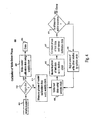
- FIG 4 shows a flowchart of a process 400 for a calibration of a write driver phase of a disc reader/recorder device.
- process 400 performs write synchronization of new data with old data on a disk media.
- Process 400 is substantially similar to process 300, however, process 400 shows more specific steps 401-409 as performed by the disc reader/recorder driver.
- Steps 401-403 and step 420 show the process when writing to a blank "virgin" disk having no prerecorded data.
- Steps 402, and steps 404-409 show the process when writing to a disc containing old data and the calibration of the write clock for the new data to ensure synchronization.
- the present invention is directed towards a method and system for implementing a rewriteable format for disk based data storage devices.
- the present invention takes advantage of a timing reference available in the disk format of the media in which the data are to be stored, and uses this reference to bring the write clock into synchronism with the old data bit clock timing.
- the frequency of the data clock is 27.8 Mb/s at 4.9 m/s, corresponding to 0.1763 micron/bit, 0.53 microns for a 3T mark.
- the time interval measurements can be accomplished with a circuit that charges a capacitor at a rapid linear rate during the time interval to be measured. Then an A-to-D converter can read the voltage on the capacitor with precision corresponding to 100 ps easily.
- a D-to-A converter can drive the control voltage input of an analog voltage controlled monostable multivibrator.
- an analog voltage controlled monostable multivibrator for example, see US Patent 3403268.
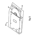
- FIG. 5 shows a diagram of a disc reader/recorder device 501 in accordance with one embodiment of the present invention.
- device 501 includes a tray mechanism 503 which loads and unloads a disc media 502.
- the embodiments of the device 501 can be configured to read/write compact discs (Cds), DVDs, minidisks, or the like.
- the disc reader/recorder device 501 includes the disc reading and recording means, the timing circuitry means (e.g., write and read clock PLLs, etc.), and the like required to implement the functions of the present invention (e.g., process 300 and process 400).
Landscapes
- Engineering & Computer Science (AREA)
- Multimedia (AREA)
- Optical Recording Or Reproduction (AREA)
- Signal Processing For Digital Recording And Reproducing (AREA)
Abstract
Description
In the present embodiment, there are three signals that must be involved in the synchronization:
Claims (10)
- A method for synchronizing newly recorded data with previously recorded data in a disk-based data storage system, comprising the steps of:a) measuring a first difference between a wobble reference signal and previously recorded data (301);b) writing test data on a test track to measure a second difference between the wobble reference signal and the test data, the test data written synchronous with a write clock (302);c) determining a delay offset by comparing the first difference and the second difference (303); andd) writing new data using the write clock and the delay offset such that the new data is synchronized with the old data (304).
- A method as claimed in Claim 1 wherein step b) further includes the steps of:writing the test data to the test track with the delay offset set to zero (302);reading the test data from the test track (303);subtracting the first difference from the second difference to determine the delay offset for the write clock calibration delay (303).
- A method as claimed in Claim 1 or 2 wherein step d) further includes the step of inserting the delay offset into a wobble-to-laser path to cause the new data to have the same epoch as the previously recorded data.
- A method as claimed in any of Claims 1 to 3 further including the step of checking whether an error value is within predetermined limits (306), wherein the error value is the difference between the first difference from step a) and the second difference from step b).
- A method as claimed in Claim 4 further including the step of adjusting the write clock in accordance with the error value, if the error value is outside the predetermined limits (307).
- A disc based data storage system for editing old data on a disc media with new data, comprising:a) means for measuring a first difference between a wobble reference signal and previously recorded data (501);b) means for writing test data on a test track to measure a second difference between the wobble reference signal and the test data, the test data written synchronous with a write clock (501);c) means for determining a delay offset by comparing the first difference and the second difference (501); andd) means for writing new data using the write clock and the delay offset such that the new data is synchronized with the old data (501).
- A system as claimed in Claim 6 wherein the means for writing test data on a test track to measure a second difference between the wobble reference signal and the test data, further comprises:means for writing the test data to the test track with the delay offset set to zero (501);means for reading the test data from the test track (501);means for subtracting the first difference from the second difference to determine the delay offset for the write clock calibration delay (501).
- A system as claimed in Claim 6 or 7 wherein the means for writing new data using the write clock and the delay offset such that the new data is synchronized with the old data further includes means for inserting the delay offset into a wobble-to-laser path to cause the new data to have the same epoch as the previously recorded data(501).
- A system as claimed in any of Claims 6 to 8 further comprising means for checking whether an error value is within predetermined limits, wherein the error value is the difference between the first difference and the second difference (501).
- A system as claimed in Claim 9 further comprising means for adjusting the write clock in accordance with the error value, if the error value is outside the predetermined limits (501).
Applications Claiming Priority (2)
| Application Number | Priority Date | Filing Date | Title |
|---|---|---|---|
| US923737 | 2001-08-06 | ||
| US09/923,737 US20030026182A1 (en) | 2001-08-06 | 2001-08-06 | Method and system for write clock synchronization in a data storage system |
Publications (2)
| Publication Number | Publication Date |
|---|---|
| EP1291875A2 true EP1291875A2 (en) | 2003-03-12 |
| EP1291875A3 EP1291875A3 (en) | 2004-05-19 |
Family
ID=25449188
Family Applications (1)
| Application Number | Title | Priority Date | Filing Date |
|---|---|---|---|
| EP02255469A Withdrawn EP1291875A3 (en) | 2001-08-06 | 2002-08-05 | A method and system for write clock synchronization in a data storage system |
Country Status (4)
| Country | Link |
|---|---|
| US (1) | US20030026182A1 (en) |
| EP (1) | EP1291875A3 (en) |
| JP (1) | JP2003178531A (en) |
| CN (1) | CN1407554A (en) |
Families Citing this family (6)
| Publication number | Priority date | Publication date | Assignee | Title |
|---|---|---|---|---|
| ATE471340T1 (en) * | 2004-02-11 | 2010-07-15 | Amylin Pharmaceuticals Inc | PEPTIDES OF THE AMYLIN FAMILY, METHOD FOR THE PRODUCTION AND USE THEREOF |
| US7248549B2 (en) * | 2004-07-30 | 2007-07-24 | Agere Systems Inc. | System for locking a clock onto the frequency of data recorded on a storage medium |
| US7782726B2 (en) | 2006-03-07 | 2010-08-24 | Marvell World Trade Ltd. | Write splice for optical recording channels |
| JP4539747B2 (en) * | 2008-03-31 | 2010-09-08 | ソニー株式会社 | LASER DRIVE CIRCUIT, RECORDING COMPENSATION METHOD THEREOF, AND OPTICAL DISK DEVICE |
| US8400891B2 (en) * | 2009-06-26 | 2013-03-19 | Seagate Technology Llc | Delay line on a movable substrate accessing data storage media |
| CN110971326B (en) | 2018-09-28 | 2021-07-16 | 华为技术有限公司 | A method and device for time synchronization |
Family Cites Families (8)
| Publication number | Priority date | Publication date | Assignee | Title |
|---|---|---|---|---|
| US3403268A (en) * | 1964-12-18 | 1968-09-24 | Navy Usa | Voltage controlled pulse delay |
| JP2647875B2 (en) * | 1987-12-25 | 1997-08-27 | 株式会社日立製作所 | Magneto-optical signal recording / reproducing method |
| JP2655682B2 (en) * | 1988-06-08 | 1997-09-24 | 株式会社日立製作所 | Magneto-optical information recording / reproducing device |
| US5559778A (en) * | 1993-12-28 | 1996-09-24 | Sony Corporation | Apparatus and method for completing an incomplete recording on an optical disc |
| JP3447942B2 (en) * | 1998-01-14 | 2003-09-16 | パイオニア株式会社 | Information recording apparatus and information recording method |
| JP4102483B2 (en) * | 1998-06-02 | 2008-06-18 | パイオニア株式会社 | Information recording device |
| US6445656B1 (en) * | 1999-04-13 | 2002-09-03 | Ricoh Company, Ltd. | Optical recording/reproducing method and apparatus for optical storage media |
| US6636467B1 (en) * | 2000-06-30 | 2003-10-21 | Hewlett-Packard Development Company, L.P. | Method and apparatus for accurately calibrating the timing of a write onto storage media |
-
2001
- 2001-08-06 US US09/923,737 patent/US20030026182A1/en not_active Abandoned
-
2002
- 2002-07-23 JP JP2002213293A patent/JP2003178531A/en not_active Withdrawn
- 2002-08-05 EP EP02255469A patent/EP1291875A3/en not_active Withdrawn
- 2002-08-06 CN CN02131804.2A patent/CN1407554A/en active Pending
Also Published As
| Publication number | Publication date |
|---|---|
| US20030026182A1 (en) | 2003-02-06 |
| CN1407554A (en) | 2003-04-02 |
| JP2003178531A (en) | 2003-06-27 |
| EP1291875A3 (en) | 2004-05-19 |
Similar Documents
| Publication | Publication Date | Title |
|---|---|---|
| US9305581B2 (en) | Systems and methods for memory efficient repeatable run out processing | |
| JP2845915B2 (en) | Information reproducing method and information reproducing apparatus | |
| US7679852B2 (en) | Adjustment of read/write clock edge timing | |
| US6201778B1 (en) | Optical disk with a groove for defining serial data modulated into a signal using phase and frequency modulation | |
| US5592456A (en) | Information reproducing apparatus and method | |
| EP1291875A2 (en) | A method and system for write clock synchronization in a data storage system | |
| US6631108B1 (en) | Method for accurate positioning of data marks and spaces on an optical disc | |
| US20100118427A1 (en) | Eliminating sector synchronization fields for bit patterned media | |
| US6654331B1 (en) | Method for accurate positioning of data marks and spaces on an optical disc | |
| US6538966B1 (en) | Accurate positioning of data marks and spaces relative to groove wobble on a rewritable optical disc | |
| US6255911B1 (en) | PLL circuit protected against noise and missing pulses in a reference signal | |
| TWI230378B (en) | Apparatus and method for connecting interrupted recording | |
| US6961293B2 (en) | Method and related device for achieving stable writing state of compact disk drive by adjusting writing clock | |
| JPH02223066A (en) | Optical recording and reproducing device | |
| JP2003178531A5 (en) | ||
| KR20050029212A (en) | Sync signal detecting device and sync signal detecting method | |
| US20030081518A1 (en) | Recording power adjusting method and optical information record apparatus using the same | |
| KR20040069936A (en) | Information recording method and optical disk device | |
| JP3978130B2 (en) | Recording method and disk recording apparatus | |
| US7145838B2 (en) | Method and apparatus for performing target search on optical storage disc | |
| JP2003173535A (en) | Optical disk recording / reproducing apparatus and optical disk recording method | |
| CN1290089C (en) | Disk recording device and disk recording methoed | |
| JP3089557B2 (en) | Disc-shaped recording medium | |
| JP2984008B2 (en) | Disc-shaped optical recording medium | |
| US20040145990A1 (en) | Writable area detection device for optical recording/reproducing apparatus and method thereof |
Legal Events
| Date | Code | Title | Description |
|---|---|---|---|
| PUAI | Public reference made under article 153(3) epc to a published international application that has entered the european phase |
Free format text: ORIGINAL CODE: 0009012 |
|
| AK | Designated contracting states |
Kind code of ref document: A2 Designated state(s): AT BE BG CH CY CZ DE DK EE ES FI FR GB GR IE IT LI LU MC NL PT SE SK TR Designated state(s): AT BE BG CH CY CZ DE DK EE ES FI FR GB GR IE IT LI LU MC NL PT SE SK TR |
|
| AX | Request for extension of the european patent |
Extension state: AL LT LV MK RO SI |
|
| PUAL | Search report despatched |
Free format text: ORIGINAL CODE: 0009013 |
|
| AK | Designated contracting states |
Kind code of ref document: A3 Designated state(s): AT BE BG CH CY CZ DE DK EE ES FI FR GB GR IE IT LI LU MC NL PT SE SK TR |
|
| AX | Request for extension of the european patent |
Extension state: AL LT LV MK RO SI |
|
| RIC1 | Information provided on ipc code assigned before grant |
Ipc: 7G 11B 7/00 B Ipc: 7G 11B 20/10 B Ipc: 7G 11B 27/034 A |
|
| 17P | Request for examination filed |
Effective date: 20041115 |
|
| AKX | Designation fees paid |
Designated state(s): DE FR GB |
|
| STAA | Information on the status of an ep patent application or granted ep patent |
Free format text: STATUS: THE APPLICATION HAS BEEN WITHDRAWN |
|
| 18W | Application withdrawn |
Effective date: 20060313 |