EP1291852A2 - Magnetic disk drive and control method thereof - Google Patents
Magnetic disk drive and control method thereof Download PDFInfo
- Publication number
- EP1291852A2 EP1291852A2 EP02015555A EP02015555A EP1291852A2 EP 1291852 A2 EP1291852 A2 EP 1291852A2 EP 02015555 A EP02015555 A EP 02015555A EP 02015555 A EP02015555 A EP 02015555A EP 1291852 A2 EP1291852 A2 EP 1291852A2
- Authority
- EP
- European Patent Office
- Prior art keywords
- vcm
- magnetic disk
- temperature
- seek
- velocity
- Prior art date
- Legal status (The legal status is an assumption and is not a legal conclusion. Google has not performed a legal analysis and makes no representation as to the accuracy of the status listed.)
- Granted
Links
Images




Classifications
-
- G—PHYSICS
- G11—INFORMATION STORAGE
- G11B—INFORMATION STORAGE BASED ON RELATIVE MOVEMENT BETWEEN RECORD CARRIER AND TRANSDUCER
- G11B21/00—Head arrangements not specific to the method of recording or reproducing
- G11B21/02—Driving or moving of heads
-
- G—PHYSICS
- G11—INFORMATION STORAGE
- G11B—INFORMATION STORAGE BASED ON RELATIVE MOVEMENT BETWEEN RECORD CARRIER AND TRANSDUCER
- G11B33/00—Constructional parts, details or accessories not provided for in the other groups of this subclass
- G11B33/14—Reducing influence of physical parameters, e.g. temperature change, moisture, dust
- G11B33/1406—Reducing the influence of the temperature
-
- G—PHYSICS
- G11—INFORMATION STORAGE
- G11B—INFORMATION STORAGE BASED ON RELATIVE MOVEMENT BETWEEN RECORD CARRIER AND TRANSDUCER
- G11B5/00—Recording by magnetisation or demagnetisation of a record carrier; Reproducing by magnetic means; Record carriers therefor
- G11B5/48—Disposition or mounting of heads or head supports relative to record carriers ; arrangements of heads, e.g. for scanning the record carrier to increase the relative speed
- G11B5/54—Disposition or mounting of heads or head supports relative to record carriers ; arrangements of heads, e.g. for scanning the record carrier to increase the relative speed with provision for moving the head into or out of its operative position or across tracks
- G11B5/55—Track change, selection or acquisition by displacement of the head
- G11B5/5521—Track change, selection or acquisition by displacement of the head across disk tracks
- G11B5/5526—Control therefor; circuits, track configurations or relative disposition of servo-information transducers and servo-information tracks for control thereof
- G11B5/553—Details
- G11B5/5547—"Seek" control and circuits therefor
-
- G—PHYSICS
- G11—INFORMATION STORAGE
- G11B—INFORMATION STORAGE BASED ON RELATIVE MOVEMENT BETWEEN RECORD CARRIER AND TRANSDUCER
- G11B5/00—Recording by magnetisation or demagnetisation of a record carrier; Reproducing by magnetic means; Record carriers therefor
- G11B5/48—Disposition or mounting of heads or head supports relative to record carriers ; arrangements of heads, e.g. for scanning the record carrier to increase the relative speed
- G11B5/54—Disposition or mounting of heads or head supports relative to record carriers ; arrangements of heads, e.g. for scanning the record carrier to increase the relative speed with provision for moving the head into or out of its operative position or across tracks
- G11B5/55—Track change, selection or acquisition by displacement of the head
- G11B5/5521—Track change, selection or acquisition by displacement of the head across disk tracks
- G11B5/5526—Control therefor; circuits, track configurations or relative disposition of servo-information transducers and servo-information tracks for control thereof
- G11B5/553—Details
- G11B5/5534—Initialisation, calibration, e.g. cylinder "set-up"
-
- G—PHYSICS
- G11—INFORMATION STORAGE
- G11B—INFORMATION STORAGE BASED ON RELATIVE MOVEMENT BETWEEN RECORD CARRIER AND TRANSDUCER
- G11B5/00—Recording by magnetisation or demagnetisation of a record carrier; Reproducing by magnetic means; Record carriers therefor
- G11B5/48—Disposition or mounting of heads or head supports relative to record carriers ; arrangements of heads, e.g. for scanning the record carrier to increase the relative speed
- G11B5/54—Disposition or mounting of heads or head supports relative to record carriers ; arrangements of heads, e.g. for scanning the record carrier to increase the relative speed with provision for moving the head into or out of its operative position or across tracks
- G11B5/55—Track change, selection or acquisition by displacement of the head
- G11B5/5521—Track change, selection or acquisition by displacement of the head across disk tracks
- G11B5/5565—Track change, selection or acquisition by displacement of the head across disk tracks system adaptation for compensation of variations of physical parameters, e.g. temperature
Definitions
- the present invention relates to a magnetic disk drive, and, more particularly, to a magnetic disk drive that ensures excellent fault tolerance by preventing an excessive rise in coil temperature of a voice coil motor (hereinafter referred to as "VCM") even when there is frequent access of data to a magnetic disk at high temperature in the magnetic disk dive that performs the seek operation of a magnetic head by the VCM.
- VCM voice coil motor
- the "motor controller" disclosed in the Japanese Patent Laid-Open No. Hei 11-341850 detects a current that is supplied to the motor and incorporates the current in the CPU, then compares the current with several reference temperatures. The rotational velocity of the motor is adjusted by adjusting the rotational speed of the motor based on the result, thereby preventing the heating of the motor.
- a VCM has been used as a mechanism for moving a magnetic head to a predetermined track.
- a control means for preventing the heating of the motor must also be provided in this VCM when the magnetic disk drive is frequently accessed.
- the magnetic disk drive that uses the VCM introduces the following digital control system. That is, the magnetic disk drive reads position information recorded on the magnetic disk at equal time intervals in the circumferential direction to position the magnetic head for data access in a desired track and transfers the position information to the CPU, then performs predetermined operation.
- a D/A converter converts an operation result to an analog signal.
- a VCM AMP converts this voltage to a current and applies the current to the VCM.
- a magnetic field is applied to the VCM by a magnet arranged in the vicinity in this manner.
- VCM AMP makes a current flow in the VCM for positioning operation
- drive force that propels an actuator is generated by electromagnetic induction, thereby enabling the seek operation that moves the magnetic head to the predetermined track.
- a coil moves in a magnetic field, back electromotive force (hereinafter referred to as "BEMF") that is proportional to the traveling velocity occurs.
- BEMF back electromotive force
- BEMF Vvcm - Ivcm x Rvcm
- the BEMF can be calculated from the aforementioned (Equation 1) if the VCM voltage and the VCM current can be measured regarding the VCM coil resistance as a constant.
- the VCM coil resistance varies with the heat dissipation when the supply of a high VCM current by the seek operation and the ambient temperature of a magnetic disk drive.
- the VCM coil resistance is generally expressed by (Equation 2).
- Rvcm R20 x (1 + C x ⁇ t)
- VCM coil resistance has temperature sensitivity like this, a slight error occurs. If the VCM coil resistance (Rvcm) can be measured, however, ⁇ t can be calculated back by transforming (Equation 2), thereby also enabling acquisition of the VCM temperature.
- some magnetic disk drives have a load and unload mechanism that shunts a magnetic head to an area on the outer circumference than a disk surface if the power of the magnetic disk drives is not supplied when a spindle motor that rotates a disk is in a stopped state except in the read and write operation.
- the same measurement may be made by pushing the actuator against the internal-surface stopper.
- the VCM coil resistance has temperature sensitivity and varies with the seek operation and ambient temperature.
- the data access pattern of a magnetic disk drive differs in sequential access and random access, and there are various access data lengths in one command.
- the severest pattern is a short access data and the amount of VCM current required for the seek operation per hour is high. Specifically, in this case, deceleration current is supplied when the data length is 1 or 0 sector and seek operation reaches the specified maximum velocity continuing making the current that accelerates an actuator flow.
- Fig. 7 is a diagram showing the general relationship between the VCM current and the seek velocity.
- a temperature change does not occur steeply in the one-time seek operation, but slowly changes by the execution of multiple times of seek operations.
- a severe seek continues several 10 ms or more and a measurable temperature change appears.
- the heat resistance temperature of a mechanism component is exceeded and the characteristics of a functional component vary, thereby causing a fault to occur.
- Concerning such symptom for example, as described in the Japanese Patent Laid-Open No. Hei 6-119008, when a temperature sensor is provided inside the drive and a specified value is exceeded, there is a method of stopping operation.
- this method may not be able to estimate the VCM coil temperature correctly because the acceleration capability varies with the power supply voltage, thereby fluctuating the power supply voltage.
- the present invention is made under such circumstances and it is therefore a future of the present invention to provide a magnetic disk drive having excellent fault tolerance that will not generate a fault even in such severe environment as the issue of a high humidity and high frequency command by estimating the VCM coil temperature itself and, as a result, moving to the seek control mode that suppresses an excessive temperature rise without using a special device, such as a temperature sensor, and requiring a special operation for the measurement of the VCM coil temperature and deteriorating access performance.
- the control method of a magnetic disk drive that performs seek operation by a VCM for positioning a magnetic head of the present invention in a predetermined track, first, measures the VCM current supplied to the VCM and the VCM voltage applied to both ends of the VCM. Subsequently, based on this measurement result, BEMF is calculated. At seek operation, the position information located on the magnetic disk is sampled. The traveling velocity of the magnetic disk is detected from the difference of the position information of this sample result and the VCM coil temperature is estimated from the difference between the detected traveling velocity and the calculated BEMF. Further, when this estimated coil temperature exceeds a specified value, the VCM is made to move to the low velocity seek mode.
- the mechanism that performs the seek control of a magnetic disk drive is constituted of a velocity control system.
- the traveling velocity for the detection of the traveling velocity in this case, as shown in Fig. 4 later, in most cases, the position information that is arranged on a magnetic disk surface at equal intervals in the circumferential direction and radially in the radial direction is sampled and the difference between the samples is used as the traveling velocity.
- This detection velocity is calculated from a track on which a magnetic head moves actually.
- This velocity detection method is fixed in sensitivity regardless of temperature environment and voltage environment and high in accuracy.
- BEMF can be operated even in seek operation and an error ⁇ BEMF due to a VCM coil temperature change is contained.
- the BEMF detected in the state containing the VCM coil temperature change appears as (Equation 4).
- Kf also includes temperature sensitivity in the same manner as Rvcm here.
- the temperature sensitivity is sufficiently low and can be ignored because it is known that the temperature itself will also not rise to the temperature at which the predetermined temperature is added to the ambient temperature of the drive. That is, approximately, the BEMF may be assumed to be primarily proportional to the traveling velocity of seek operation.
- a temperature difference from 20°C can be extracted and the VCM coil temperature can be estimated.
- the magnetic disk drive of the present invention monitors the ⁇ Rvcm obtained in (Equation 8). On reaching the predetermined temperature that will exceed the heat resistance temperature of the VCM coil portion, the magnetic disk drive decreases the seek traveling velocity and moves to the low velocity seek mode that suppresses the heat dissipation of the VCM. Further, on decreasing below the predetermined temperature, the magnetic disk drive returns to the normal seek mode.
- Fig. 1 is a block diagram of the magnetic disk drive according to the present invention.
- the magnetic disk drive of the present invention that records data and follows rotary operation is concentrated in an HDA (head disk assembly) 7.
- the HDA 7 includes of a magnetic disk 1, a spindle motor 2, a magnetic head 3, an arm 4, a VCM 5, and a preamplifier 6.
- the spindle motor 2 rotates the magnetic disk 1.
- the magnetic head 3 records digital information and performs reproduction operation on the magnetic disk 1.
- the arm 4 supports the magnetic head 1 and the VCM 5 drives the magnetic head 1 via this arm 4.
- the preamplifier 6 is an amplifier that amplifies the data and position information read by the magnetic head 1.
- the magnetic disk drive of the present invention has a channel 8, a gate array 9, a CPU 10, a D/A converter 11, and a VCM AMP 12.
- the channel 8 demodulates the data and position information read from the preamplifier 6 into a digital signal.
- the gate array 9 transfers the position information obtained from this channel 8 to the CPU 10.
- the CPU 10 calculates a manipulated variable for positioning control based on the position information transferred from the gate array 9.
- the D/A converter 11 converts a digital quantity and an analog quantity.
- the VCM AMP 12 supplies the current to the VCM.
- the calculation result of the manipulated variable from the CPU 10 is converted to an analog signal by the D/A converter 11 and voltage-to-current-converted by the VCM AMP 12. Consequently, a control system in which a current is supplied to the VCM 5 and the magnetic head 3 is driven is formed.
- Fig. 2 shows the relationship between the VCM current and seek velocity, and ⁇ BEMF (1).
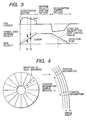
- Fig. 3 shows the relationship between the VCM current and seek velocity, and ⁇ BEMF (2).
- Fig. 4 shows a magnetic disk and the position information located on it.
- the seek control as shown in Fig. 2, there is a section in which the velocity control facing a target position is started and accelerated, and there is a section that is controlled at uniform velocity when the maximum seek velocity is reached.
- the acceleration section to extract the power supply voltage and the maximum acceleration capability of a mechanism system, in most cases, the VCM current is saturated and the maximum current is supplied.
- the seek control mechanism is mostly constituted of a velocity control system in this manner.
- the position information including a track number
- travel is calculated from the difference between the radial position of the current sample and the radial position of the previous sample and the value in which this travel is divided by the time of sample interval Ts is used as a traveling velocity. Accordingly, the velocity calculated in this calculation is the position information on which a magnetic head actually passed through, and this detection method is used when there are extremely small offset and uneven sensitivity.
- the calculation of BEMF requires the information about the VCM current and the VCM voltage.
- the VCM current is obtained by detecting a voltage on both ends of a current sense resistor Rs 14 of low resistance inserted into the VCM in series using a VCM current detection AMP 15 that detects this voltage. Besides, in most cases, this AMP 15 is usually incorporated in the VCM AMP.
- the voltage on both ends of the VCM is detected by a VCM voltage detection AMP 16 in the same manner.
- the information about these VCM current and VCM voltage is input to the A/D converter 13 respectively.
- the BEMF as expressed in (Equation 1), is obtained by multiplying a VCM resistance value Rvcm by the A/D conversion result of a VCM current Ivcm and calculating the difference with the A/D conversion result of the VCM voltage.
- the BEMF is calculated in this manner.
- the VCM coil resistance has high temperature sensitivity. Accordingly, when the BEMF is calculated in the state containing the error ⁇ BEMF due to a temperature change, the trace shown in the dotted line of Fig. 2 is formed. In the area to which a high VCM current is supplied, such as the acceleration section or the deceleration section, a waveform having an offset error that is proportional to the amount of VCM current supplied is formed in comparison with the velocity detected during seek control.
- VCM current and VCM voltage that become the cause of calculating the BEMF are incorporated into a CPU via the A/D converter 13 of definite resolution, desirably, they are calculated in a section in which the absolute value is high.
- BEMF Vvcm - Ivcm x Rvcm - Lvcm x dIvcm/dt
- the BEMF in the section in which the rate of change of the VCM current Ivcm is high, because the effect of the inductance Lvcm appears in the BEMF, the time variance of the BEMF is high and the BEMF becomes difficult to detect. Accordingly, in the detection of the BEMF, the BEMF can be measured with good accuracy in the area in which the absolute value of the VCM current is high and the rate of change of the VCM current is low. From this viewpoint an acceleration area or a deceleration area is desirable. However, desirably, the BEMF is measured in the acceleration section, because both the VCM current and VCM voltage are stable in the acceleration area in which the VCM current is saturated.
- the measurement may also be made using the average of the section for the fixed time from T1 to T2, as shown in Fig. 3, instead of the single point of the acceleration section as shown in Fig. 2.
- Fig. 5 is a flowchart showing the control procedure of seek operation according to the magnetic disk drive of the present invention.
- the seek that is executed currently judges whether it should be switched to the low velocity seek mode, and, consequently, the seek maximum velocity data is set. That is, when the low velocity seek mode flag is On (S501), the seek maximum velocity is set to a low velocity value (S502). When the low velocity seek mode flag is Off, the seek maximum velocity is set to a normal value (S503). This low velocity seek mode flag is set to On when ⁇ t exceeds a preset value at previous seek.
- the ⁇ BEMF is calculated (S505, S506).
- the ⁇ t is calculated (S507). If the ⁇ t exceeds a preset value (S508), the low velocity seek mode flag is set to On (S509). If it is below the preset value, the low velocity seek mode flag is set to Off (S510).
- the heat dissipation of the VCM can be suppressed because the VCM current required for single seek control decreases.
- the preset value that moves to this low velocity seek mode is set below the VCM coil temperature and the heat resistance temperature of a mechanism system.
- the condition of returning to the normal seek control mode also includes a method of assuming hysteresis (method of considering the history of the past state), such as the case where the temperature falls short of specified temperature or goes below fixed temperature from the preset temperature.
- Fig. 6 shows the relationship between the VCM current and seek velocity according to the second embodiment of the present invention.
- This embodiment prevents the heat dissipation of the VCM by delaying the next seek start at least wait time Td and decreasing the amount of VCM current to be applied within the unit time.
- the CPU 10 is external. Accordingly, a description is made so that the calculation of BEMF, the detection of seek velocity, and the estimation of VCM coil temperature can be performed. This function is incorporated in the VCM AMP 12 and may also be provided as a chip.
- a magnetic disk drive that performs the seek operation of a magnetic head by the VCM.
- the magnetic disk drive is excellent in fault tolerance that will not generate a fault even under severe environment such as a high temperature and the issue of high frequency command, by estimating the VCM coil temperature and as a result, moving to the seek control mode that suppresses an excessive temperature rise, without using a special device, such as a temperature sensor, and without requiring special operation for the measurement of the VCM coil temperature, and without deteriorating the access performance.
Landscapes
- Moving Of Head For Track Selection And Changing (AREA)
- Moving Of Heads (AREA)
Abstract
Description
- Vvcm:
- VCM both-end voltage
- Ivcm:
- Current flowing in a VCM
- Rvcm:
- Coil resistance of a VCM
- R20:
- VCM coil resistance when the VCM ambient temperature is 20°C
- C:
- Temperature sensitivity constant
- Δt:
- Temperature difference of 20°C with the VCM coil temperature
Consequently, access performance will deteriorate considerably. Moreover, this Japanese Patent Laid-Open No. 2000- 222837 also describes that the measurement of the VCM coil resistance is executed in a "following" state. In actual, a small amount of the VCM current can be found in the "following" state. When the method of A/D-converting the VCM current via the VCM current detection AMP is used, an A/D conversion value reaches an extremely small amount in comparison with the resolution. Accordingly, a measurement result with good accuracy is difficult to obtain.
- ΔRvcm:
- Variation due to a temperature change of the VCM coil resistance
- ΔBEMF:
- BEMF detection error due to the effect of ΔRvcm
- Velocity:
- Traveling velocity signal detected for seek control
- Kf:
- Drive thrust constant [N/A] per current applied to the VCM
- Lvcm:
- VCM coil inductance
Claims (5)
- A magnetic disk drive, comprising:a voice coil motor (VCM) 5 for performing seek operation that positions a magnetic head 3 in a predetermined track:a VCM AMP 12 for measuring a VCM current supplied to said VCM and a VCM voltage applied to both ends of said VCM;a CPU 10 for calculating a VCM back electromotive force (BEMF) based on a measurement result by said VCM AMP;a Gate Array 9 for sampling position information located on a magnetic disk at said seek operation;said CPU for detecting a traveling velocity of said magnetic head with the difference among said position information sampled by said Gate Array;said CPU for estimating a temperature of said VCM from the difference between said traveling velocity and said VCM BEMF; andsaid CPU for moving said VCM in a low velocity seek mode when said temperature of said VCM exceeds a specified value.
- The magnetic disk drive according to claim 1, wherein said estimation of said temperature of said VCM is executed during acceleration of said seek operation.
- The magnetic disk drive according to claim 1, wherein wait time is inserted between consecutive seek operations, and an execution frequency of seek operation is reduced when said estimation of said temperature of said VCM exceeded a specified value.
- The magnetic disk drive according to claim 1, wherein a circuit for executing a function that calculates said BEMF, a function that detects said traveling velocity, and a function that estimates said temperature of said VCM, is integrated and mounted in a circuit portion that supplies a current to said VCM.
- A control method of a magnetic disk drive that performs seek operation by a voice coil motor (VCM) 5 for positioning a magnetic head 3 in a predetermined track, comprising the steps of:measuring a VCM current supplied to said VCM and a VCM voltage applied to both ends of said VCM;calculating VCM back electromotive force (BEMF) based on said VCM current and said VCM voltage;sampling positioning information located on a magnetic disk at said seek operation;detecting a traveling velocity of said magnetic head with the difference among said positioning information sampled;estimating a temperature of said VCM from the difference between said traveling velocity and said VCM BEMF; andmoving said VCM in a low velocity seek mode when said temperature of said VCM exceeds a specified value.
Applications Claiming Priority (2)
| Application Number | Priority Date | Filing Date | Title |
|---|---|---|---|
| JP2001272997A JP2003085902A (en) | 2001-09-10 | 2001-09-10 | Magnetic disk drive |
| JP2001272997 | 2001-09-10 |
Publications (3)
| Publication Number | Publication Date |
|---|---|
| EP1291852A2 true EP1291852A2 (en) | 2003-03-12 |
| EP1291852A3 EP1291852A3 (en) | 2003-10-22 |
| EP1291852B1 EP1291852B1 (en) | 2008-09-10 |
Family
ID=19098272
Family Applications (1)
| Application Number | Title | Priority Date | Filing Date |
|---|---|---|---|
| EP02015555A Expired - Lifetime EP1291852B1 (en) | 2001-09-10 | 2002-07-11 | Magnetic disk drive and control method thereof |
Country Status (5)
| Country | Link |
|---|---|
| US (1) | US6909575B2 (en) |
| EP (1) | EP1291852B1 (en) |
| JP (1) | JP2003085902A (en) |
| KR (1) | KR100505777B1 (en) |
| DE (1) | DE60228799D1 (en) |
Families Citing this family (22)
| Publication number | Priority date | Publication date | Assignee | Title |
|---|---|---|---|---|
| US6892275B2 (en) * | 2002-02-05 | 2005-05-10 | Quantum Corporation | Storage system utilizing an active subset of drives during data storage and retrieval operations |
| CN1322509C (en) * | 2002-10-28 | 2007-06-20 | 松下电器产业株式会社 | Head positioning controller, disk device cooperating same, and head positioning control method |
| US6937427B2 (en) * | 2003-06-19 | 2005-08-30 | Seagate Technology Llc | Method and apparatus for measuring the back EMF of a disc drive VCM |
| US6995946B2 (en) * | 2003-06-27 | 2006-02-07 | Seagate Technology Llc | Temperature compensation of seek profiles in data storage devices |
| US7136247B2 (en) * | 2003-09-30 | 2006-11-14 | Hitachi Global Storage Technologies Netherlands B.V. | Drive temperature self-adjustment for temperature-sensitive measurements |
| US6934107B2 (en) * | 2003-09-30 | 2005-08-23 | Hitachi Global Storage Technologies Netherlands B.V. | Hard disk drive having drive temperature self-adjustment for temperature-sensitive measurements |
| JP4408213B2 (en) | 2003-11-18 | 2010-02-03 | 東芝ストレージデバイス株式会社 | Storage device and actuator movement control method |
| US7609472B2 (en) * | 2004-06-01 | 2009-10-27 | Hewlett-Packard Development Company, L.P. | Power and thermal management for a hard drive |
| KR100674915B1 (en) * | 2004-10-13 | 2007-01-26 | 삼성전자주식회사 | Method and apparatus for driving a regular velocity of a spindle motor |
| US7437502B1 (en) | 2005-04-20 | 2008-10-14 | Western Digital Technologies, Inc. | Disk drive adjusting operating mode based on historical proximity of host commands |
| US7199966B1 (en) | 2005-06-28 | 2007-04-03 | Western Digital Technologies, Inc. | Disk drive adjusting seek profile for variable seek times to reduce power dissipation |
| US7656600B2 (en) * | 2006-08-25 | 2010-02-02 | Seagate Technology Llc | Monitoring transducer potential to detect an operating condition |
| US7450334B1 (en) | 2007-06-28 | 2008-11-11 | Western Digital Technologies, Inc. | Disk drive adjusting predictive caching based on temperature of voice coil motor |
| JP2010049769A (en) * | 2008-08-25 | 2010-03-04 | Toshiba Storage Device Corp | Storage device, method for controlling storage device, and circuit for controlling storage device |
| US8090902B1 (en) | 2009-05-22 | 2012-01-03 | Western Digital Technologies, Inc. | Disk drive adjusting command execution in response to control circuitry die temperature |
| JP4947674B2 (en) * | 2010-11-02 | 2012-06-06 | ルネサスエレクトロニクス株式会社 | Semiconductor integrated circuit for driving motor and semiconductor integrated circuit for motor |
| US9136787B2 (en) * | 2012-10-25 | 2015-09-15 | Texas Instruments Incorporated | Back EMF monitor for motor control |
| US10143124B2 (en) | 2015-02-24 | 2018-12-04 | Agco Corporation | Locking link assembly for work machine hitch |
| JP2018156705A (en) | 2017-03-16 | 2018-10-04 | 株式会社東芝 | Magnetic disk device |
| JP2018156706A (en) * | 2017-03-17 | 2018-10-04 | 株式会社東芝 | Magnetic disk device |
| JP2025129754A (en) * | 2024-02-26 | 2025-09-05 | 株式会社東芝 | magnetic disk drive |
| JP2025187656A (en) | 2024-06-14 | 2025-12-25 | 株式会社東芝 | Magnetic disk device and control method thereof |
Family Cites Families (10)
| Publication number | Priority date | Publication date | Assignee | Title |
|---|---|---|---|---|
| JP3352715B2 (en) * | 1992-03-23 | 2002-12-03 | 松下電器産業株式会社 | Head positioning device for magnetic disk drive |
| JP2692774B2 (en) | 1992-05-29 | 1997-12-17 | インターナショナル・ビジネス・マシーンズ・コーポレイション | Device and method for dynamically controlling operating temperature of optical drive device |
| JP2902921B2 (en) * | 1993-12-02 | 1999-06-07 | 富士通株式会社 | Disk device temperature detection / control method |
| US5844743A (en) * | 1996-12-20 | 1998-12-01 | Seagate Technology, Inc. | Velocity sensing using actuator coil back-emf voltage |
| US5898286A (en) * | 1997-01-13 | 1999-04-27 | International Business Machines Corporation | Digital servo control system for a data recording disk file with improved saturation modelling |
| JP3803489B2 (en) * | 1998-05-29 | 2006-08-02 | シーケーディ株式会社 | Motor control device |
| JP3607513B2 (en) * | 1998-11-30 | 2005-01-05 | 株式会社東芝 | Speed correction value calibration method applied to a head load / unload type disk device |
| JP2000222837A (en) * | 1999-02-01 | 2000-08-11 | Toshiba Corp | Disk storage device |
| JP2001067765A (en) * | 1999-08-31 | 2001-03-16 | Hitachi Ltd | Magnetic disk drive and control method therefor |
| US6690536B1 (en) * | 2000-10-31 | 2004-02-10 | Western Digital Technologies, Inc. | Disk drive employing VCM demand current to calibrate VCM IR voltage for velocity control of an actuator arm |
-
2001
- 2001-09-10 JP JP2001272997A patent/JP2003085902A/en active Pending
-
2002
- 2002-07-11 DE DE60228799T patent/DE60228799D1/en not_active Expired - Lifetime
- 2002-07-11 EP EP02015555A patent/EP1291852B1/en not_active Expired - Lifetime
- 2002-07-19 US US10/199,233 patent/US6909575B2/en not_active Expired - Fee Related
- 2002-07-19 KR KR10-2002-0042435A patent/KR100505777B1/en not_active Expired - Fee Related
Also Published As
| Publication number | Publication date |
|---|---|
| KR20030022682A (en) | 2003-03-17 |
| US20030048571A1 (en) | 2003-03-13 |
| US6909575B2 (en) | 2005-06-21 |
| JP2003085902A (en) | 2003-03-20 |
| KR100505777B1 (en) | 2005-08-04 |
| EP1291852B1 (en) | 2008-09-10 |
| EP1291852A3 (en) | 2003-10-22 |
| DE60228799D1 (en) | 2008-10-23 |
Similar Documents
| Publication | Publication Date | Title |
|---|---|---|
| US6909575B2 (en) | Magnetic disk drive and control method thereof | |
| US5781363A (en) | Servo-free velocity estimator for coil driven actuator arm in a data storage drive | |
| US5594603A (en) | Seek control system based upon a detected temperature of a positioning mechanism in a disk device | |
| US6731450B1 (en) | Disk drive control system and method for determining the temperature of an actuator coil | |
| US5182684A (en) | Estimator positioning system and method | |
| KR100800480B1 (en) | Back EMF Calibration Method, Unloading Control Method and Disk Drive of Disk Drive Using the Same | |
| KR100532483B1 (en) | Calibration method and apparatus therefor | |
| US6917486B2 (en) | Direct detection of coil resistance | |
| US6995946B2 (en) | Temperature compensation of seek profiles in data storage devices | |
| US20040245950A1 (en) | Electrical phase compensation in BEMF spindle motor control | |
| KR20060051928A (en) | Speed-controlled disk drive head retraction after power loss | |
| US8149533B2 (en) | Load/unload control method and apparatus for a magnetic disk drive | |
| US20050201000A1 (en) | Sensing a prior head position by a motion pattern | |
| US12334119B2 (en) | Method of operating hard disk drives, corresponding control circuit, hard disk drive and processing device | |
| JP3810616B2 (en) | Magnetic disk unit load / unload unit | |
| US7170249B2 (en) | Electrical phase compensation in BEMF spindle motor control | |
| KR100255189B1 (en) | Gain estimate method of servo system | |
| US7106022B2 (en) | Velocity controlled disk drive head retraction with offset removal | |
| US12499906B1 (en) | Magnetic disk drive and control method of the same | |
| US6961204B2 (en) | Head position control method and disk storage device | |
| KR100667735B1 (en) | Actuator moving speed control device and method | |
| US8611041B2 (en) | Servo control method and apparatus in seek retry condition and disk drive apparatus using the same | |
| JPH10149611A (en) | Magnetic disk drive | |
| JPH10162526A (en) | Head positioning mechanism | |
| JPH09259555A (en) | Magnetic disk drive |
Legal Events
| Date | Code | Title | Description |
|---|---|---|---|
| PUAI | Public reference made under article 153(3) epc to a published international application that has entered the european phase |
Free format text: ORIGINAL CODE: 0009012 |
|
| AK | Designated contracting states |
Kind code of ref document: A2 Designated state(s): AT BE BG CH CY CZ DE DK EE ES FI FR GB GR IE IT LI LU MC NL PT SE SK TR Designated state(s): AT BE BG CH CY CZ DE DK EE ES FI FR GB GR IE IT LI LU MC NL PT SE SK TR |
|
| AX | Request for extension of the european patent |
Extension state: AL LT LV MK RO SI |
|
| PUAL | Search report despatched |
Free format text: ORIGINAL CODE: 0009013 |
|
| AK | Designated contracting states |
Kind code of ref document: A3 Designated state(s): AT BE BG CH CY CZ DE DK EE ES FI FR GB GR IE IT LI LU MC NL PT SE SK TR |
|
| AX | Request for extension of the european patent |
Extension state: AL LT LV MK RO SI |
|
| 17P | Request for examination filed |
Effective date: 20040415 |
|
| AKX | Designation fees paid |
Designated state(s): DE FR GB |
|
| RAP1 | Party data changed (applicant data changed or rights of an application transferred) |
Owner name: HITACHI GLOBAL STORAGE TECHNOLOGIES JAPAN, LTD. |
|
| GRAP | Despatch of communication of intention to grant a patent |
Free format text: ORIGINAL CODE: EPIDOSNIGR1 |
|
| GRAS | Grant fee paid |
Free format text: ORIGINAL CODE: EPIDOSNIGR3 |
|
| GRAA | (expected) grant |
Free format text: ORIGINAL CODE: 0009210 |
|
| AK | Designated contracting states |
Kind code of ref document: B1 Designated state(s): DE FR GB |
|
| REG | Reference to a national code |
Ref country code: GB Ref legal event code: FG4D |
|
| REF | Corresponds to: |
Ref document number: 60228799 Country of ref document: DE Date of ref document: 20081023 Kind code of ref document: P |
|
| PLBE | No opposition filed within time limit |
Free format text: ORIGINAL CODE: 0009261 |
|
| STAA | Information on the status of an ep patent application or granted ep patent |
Free format text: STATUS: NO OPPOSITION FILED WITHIN TIME LIMIT |
|
| 26N | No opposition filed |
Effective date: 20090611 |
|
| PGFP | Annual fee paid to national office [announced via postgrant information from national office to epo] |
Ref country code: FR Payment date: 20110727 Year of fee payment: 10 |
|
| PGFP | Annual fee paid to national office [announced via postgrant information from national office to epo] |
Ref country code: DE Payment date: 20110706 Year of fee payment: 10 Ref country code: GB Payment date: 20110706 Year of fee payment: 10 |
|
| GBPC | Gb: european patent ceased through non-payment of renewal fee |
Effective date: 20120711 |
|
| REG | Reference to a national code |
Ref country code: FR Ref legal event code: ST Effective date: 20130329 |
|
| PG25 | Lapsed in a contracting state [announced via postgrant information from national office to epo] |
Ref country code: FR Free format text: LAPSE BECAUSE OF NON-PAYMENT OF DUE FEES Effective date: 20120731 Ref country code: DE Free format text: LAPSE BECAUSE OF NON-PAYMENT OF DUE FEES Effective date: 20130201 Ref country code: GB Free format text: LAPSE BECAUSE OF NON-PAYMENT OF DUE FEES Effective date: 20120711 |
|
| REG | Reference to a national code |
Ref country code: DE Ref legal event code: R119 Ref document number: 60228799 Country of ref document: DE Effective date: 20130201 |