EP1291756A2 - Image-forming system with a graphical user interface having an interconnection architecture - Google Patents
Image-forming system with a graphical user interface having an interconnection architecture Download PDFInfo
- Publication number
- EP1291756A2 EP1291756A2 EP02019096A EP02019096A EP1291756A2 EP 1291756 A2 EP1291756 A2 EP 1291756A2 EP 02019096 A EP02019096 A EP 02019096A EP 02019096 A EP02019096 A EP 02019096A EP 1291756 A2 EP1291756 A2 EP 1291756A2
- Authority
- EP
- European Patent Office
- Prior art keywords
- plug
- image
- software application
- package
- interface
- Prior art date
- Legal status (The legal status is an assumption and is not a legal conclusion. Google has not performed a legal analysis and makes no representation as to the accuracy of the status listed.)
- Withdrawn
Links
Images


Classifications
-
- G—PHYSICS
- G06—COMPUTING OR CALCULATING; COUNTING
- G06F—ELECTRIC DIGITAL DATA PROCESSING
- G06F3/00—Input arrangements for transferring data to be processed into a form capable of being handled by the computer; Output arrangements for transferring data from processing unit to output unit, e.g. interface arrangements
- G06F3/12—Digital output to print unit, e.g. line printer, chain printer
- G06F3/1201—Dedicated interfaces to print systems
- G06F3/1202—Dedicated interfaces to print systems specifically adapted to achieve a particular effect
- G06F3/1203—Improving or facilitating administration, e.g. print management
- G06F3/1204—Improving or facilitating administration, e.g. print management resulting in reduced user or operator actions, e.g. presetting, automatic actions, using hardware token storing data
-
- G—PHYSICS
- G06—COMPUTING OR CALCULATING; COUNTING
- G06F—ELECTRIC DIGITAL DATA PROCESSING
- G06F3/00—Input arrangements for transferring data to be processed into a form capable of being handled by the computer; Output arrangements for transferring data from processing unit to output unit, e.g. interface arrangements
- G06F3/12—Digital output to print unit, e.g. line printer, chain printer
- G06F3/1201—Dedicated interfaces to print systems
- G06F3/1223—Dedicated interfaces to print systems specifically adapted to use a particular technique
- G06F3/1224—Client or server resources management
- G06F3/1225—Software update, e.g. print driver, modules, plug-ins, fonts
-
- G—PHYSICS
- G06—COMPUTING OR CALCULATING; COUNTING
- G06F—ELECTRIC DIGITAL DATA PROCESSING
- G06F3/00—Input arrangements for transferring data to be processed into a form capable of being handled by the computer; Output arrangements for transferring data from processing unit to output unit, e.g. interface arrangements
- G06F3/12—Digital output to print unit, e.g. line printer, chain printer
- G06F3/1201—Dedicated interfaces to print systems
- G06F3/1278—Dedicated interfaces to print systems specifically adapted to adopt a particular infrastructure
- G06F3/1284—Local printer device
-
- G—PHYSICS
- G06—COMPUTING OR CALCULATING; COUNTING
- G06F—ELECTRIC DIGITAL DATA PROCESSING
- G06F3/00—Input arrangements for transferring data to be processed into a form capable of being handled by the computer; Output arrangements for transferring data from processing unit to output unit, e.g. interface arrangements
- G06F3/12—Digital output to print unit, e.g. line printer, chain printer
- G06F3/1201—Dedicated interfaces to print systems
- G06F3/1202—Dedicated interfaces to print systems specifically adapted to achieve a particular effect
- G06F3/1203—Improving or facilitating administration, e.g. print management
- G06F3/1205—Improving or facilitating administration, e.g. print management resulting in increased flexibility in print job configuration, e.g. job settings, print requirements, job tickets
-
- G—PHYSICS
- G06—COMPUTING OR CALCULATING; COUNTING
- G06F—ELECTRIC DIGITAL DATA PROCESSING
- G06F3/00—Input arrangements for transferring data to be processed into a form capable of being handled by the computer; Output arrangements for transferring data from processing unit to output unit, e.g. interface arrangements
- G06F3/12—Digital output to print unit, e.g. line printer, chain printer
- G06F3/1201—Dedicated interfaces to print systems
- G06F3/1223—Dedicated interfaces to print systems specifically adapted to use a particular technique
- G06F3/1237—Print job management
- G06F3/1253—Configuration of print job parameters, e.g. using UI at the client
Definitions
- This invention generally relates to image-forming systems having a graphic user interface. More particularly, this invention relates to image-forming machines and methods using a graphic user interface with an interconnection architecture where a software application implements a functionality and provides a plug-in interface with another software applications.
- An image-forming systems transfers images from original documents onto paper or other medium to create a finished product such as a booklet, a folded brochure, or a tabbed notebook.
- the original documents may be in hard copy (paper or other medium) or in electronic form (floppy disk, compact disc, and the like) or may be transmitted over a network such as the Internet.
- a "print job" is the combination of original documents with instructions for producing the finished product.
- GUI graphic user interface
- the GUI permits the creation and manipulation of relationships and associations among various components of the image-forming machine and the print job. These relationships and associations may be displayed using a hierarchical approach like a tree structure or file folder structure or using some alternate form of visual indication.
- the GUI typically uses multiple software applications for implementing the various functionalities in the image-forming machine. These software applications communicate and otherwise interact with each other to provide the relationships and associations among various components of the image-forming machine and the print job.
- These software applications communicate and otherwise interact with each other to provide the relationships and associations among various components of the image-forming machine and the print job.
- the more a software product is used the more potential new features are exposed.
- Traditional software packages generally are difficult to extend. Usually, only the software company that developed the product may make changes to the software application. A new functionality desired by a customer may not fit in with the software company's goals and strategies and thus may never be implemented by the software company.
- a plug-in interface permits a new functionality to be implemented in a separate plug-in package.
- the "plug-in” package includes additional software that interacts with the original software application through the plug-in interface.
- a software product supporting a plug-in interface may have multiple plug-in software packages depending upon the number of available functionalities.
- image-forming systems have one software application that provides an image-forming management functionality and another software application that provides a document or image viewing functionality. Both of these software applications typically support plug-in interfaces for addition of new functionality.
- the image-forming management plugs-ins usually communicate with the document or image viewing plug-ins through an additional interface or inter-plug-in communication package.
- a typical inter-plug-in communication package uses a Common Object Request Broker Architecture (CORBA).
- CORBA Common Object Request Broker Architecture
- the use of an inter-plug-in communication package or interface increases the cost, the complexity of installation, and the maintenance of an image-forming system.
- synchronization issues may arise similar to those found in multi-threaded applications. Additional measures typically are implemented to avoid competitive conditions and event collisions between the software applications. These additional measures usually complicate the image-forming system.
- the invention provides an image-forming system having a graphic user interface with interconnection architecture where software applications implement functionalities and provide plug-in interfaces.
- the software applications share one or more plug-in packages connected to the plug-in interface.
- One of the software applications may be used as a plug-in.
- the image-forming system has a graphic user interface with an interconnection architecture having an image-forming management functionality and a document viewing functionality.
- the interconnection architecture has a first software application to implement the image-forming management functionality and a second software application to implement the document management functionality.
- the first software application uses a plug-in interface with the second software application to share one or more plug-in packages with the second software application.
- the image-forming system has a graphic user interface with an interconnection architecture having an image viewing functionality and an image-forming management functionality.
- the interconnection architecture has a first software application and a second software application.
- the first software application implements the image-viewing functionality.
- the second software application implements the image-forming management functionality.
- the first software application provides a plug-in interface used by the second software application.
- the first and second software applications share one or more plug-in packages in essentially the same process space.
- the plug-in packages include the second software application.
- the image-forming system has a graphical user interface with an interconnection architecture.
- the image-forming system also has a first software application, a second software application, and one or more plug-in packages.
- the first software application has a first plug-in interface.
- the second software application has a second plug-in interface.
- the one or more plug-in packages are connected to the first and second plug-in interfaces.
- the first and second software applications share the one or more plug-in packages in essentially the same process space.
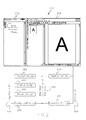
- Figure 1 represents a block diagram of an image-forming machine having a graphic user interface with interconnection architecture where a software application implements a functionality and provides a plug-in interface with another software application.
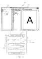
- Figure 2 represents a block diagram showing the interconnection architecture of a first software application with a second software application according to a first embodiment.
- Figure 3 represents a block diagram showing the interconnection architecture of a first software application with a second software application according to a second embodiment.
- Figure 4 represents a block diagram showing the interconnection architecture of a second software application with a second software application according to a third embodiment.
- FIG. 1 represents a block diagram of an image-forming machine 100 having a graphic user interface (GUI) 110 with interconnection architecture where a software application implements a functionality and provides a plug-in interface with another software application.
- GUI graphic user interface
- the software application implements a document or image-viewing functionality and also provides the plug-in interface to another software application implementing an image-forming management functionality in the image-forming machine 100.
- Other or additional software applications may be used to implement a functionality and provide a plug-in interface. While particular configurations and arrangements are shown, other configurations and arrangements may be used including those with other and additional components.
- the image-forming machine 100 may be an electrophotographic device such as one of the Digimaster® digital printers manufactured by Heidelberg Digital L.L.C. located in Rochester, New York.
- the image-forming machine 100 also may be another electrophotographic machine, a photocopy machine, a printing device, or the like.
- the image-forming machine 100 has a feeder 102, a marking engine 104, a finisher 106, and a printer use interface 108.
- the image-forming machine 100 may have other equipment.
- the feeder 102, the marking engine 104, the finisher 106, and the printer user interface 108 may be separate or integrated components.
- the printer user interface 108 may be a display unit with push buttons (not shown) or other activation means for inputting control parameters to the image-forming machine 100.
- the feeder 102 provides the printing or copying sheets to the printing engine 104.
- the sheets may be one or a combination of paper, transparencies, and other medium.
- the sheets may be configured with pre-punched holes, tabs, and the like.
- the marking engine 104 includes a photoconductor (not shown), one or more chargers (not shown), an exposure machine (not shown), a toning station (not shown), and a fuser station (not shown).
- the photoconductor is selectively charged and optically exposed to form an electrostatic latent image on the surface.
- Toner is deposited onto the photoconductor surface. The toner is charged, thus adhering to the photoconductor surface in areas corresponding to the electrostatic latent image.
- the toner image is transferred onto the sheet.
- the sheet In the fuser station, the sheet is heated causing the toner to fix or adhere to the paper or other medium.
- the sheet exits the marking engine 104 and enters the finisher 106, which may discharge the sheet as is or may perform one or more finishing operations such as stapling, folding, and inserting an inserted sheet.
- the GUI 110 is a separate component such as a dedicated desktop or other personal computer operatively connected to the image-forming machine 100.
- the GUI 110 also may be integrated with the printer user interface 108 or other components of the image-forming machine 100.
- the GUI 110 is operatively connected to a logic control unit (not shown) in the image-forming machine 100. Operatively connected includes transmission or communication means such as electrical, radio, network, and the like.
- the GUI and the logic control unit also may be integrated into the same component.
- the logic control unit is connected to control the feeder 102, the marking engine 104, the finisher 106, and the printer user interface 108.
- the GUI 110 comprises a display screen (not shown) and an interfacing means such as a touch screen (not shown), a keyboard (not shown), a mouse (not shown), a track ball (not shown), or a combination thereof.
- the GUI 110 also may include tear-off menus, floating buttons, dialog boxes, alternate keyboard command and mouse shortcuts, and other alternative physical input devices.
- the GUI 110 provides visual interaction with the image-forming machine 100 using one or more applications that implement one or more functionalities such as a document or image viewing functionality and an image-forming management functionality.
- document and image management functionalities are implemented via a plug-in architecture.
- a plug-in architecture allows enhancements and updates to be incorporated in a simpler and more efficient manner and without requiring recompilation of the program codes that implement the functionalities.
- Other architectures may be used.
- the document or image viewing functionality provides a centralized viewing window for viewing electronic images of the original documents in a print job.
- an Adobe Acrobat® Version 5.0 software application, manufactured by Adobe Systems, Inc. located in San Jose, California, implements the document or image viewing functionality on the image-forming machine 100.
- Other document or image viewing software applications may be used.
- the image-forming management functionality integrates applications that implement, control, or manage the image-forming machine 100.
- the image management functionality visually represents objects (documents, tickets, other entities, operations, and the like) with icons, tree structures, and pull-down menus.
- a user may interact with the image management functionality using various interaction means such as the touch screen, the mouse, the track ball, and the keyboard. Such interaction with the visual representations results in manipulation of the underlying objects.
- the image-forming management functionality may have an object-oriented appearance
- the implementation of the functionality may be by an object oriented programming language or a non-object oriented programming language.
- the image-forming management functionality is implemented by an ImageSmart® Document Mastering SmartBoardTM software application used with Digimaster® digital printers manufactured by Heidelberg Digital L.L.C. located in Rochester, New York. Other image-forming management software applications may be used.
- FIG. 2 represents a block diagram showing the interconnection architecture 250 of the ImageSmart® Document Mastering SmartBoardTM (Desktop) software application 252 with Adobe Acrobat® software application 254 according to a first embodiment.
- the SmartBoardTM (Desktop) 252 has an ImageSmart application-programming interface 256 connected to a PageOptions desktop plug-in 262, a PrintTicket desktop plug-in 264, a Document desktop plug-in 266, and a ProductionPrint desktop plug-in 268.
- the desktop plug-in packages 262, 264, 266, and 268 are additional software applications provided with the ImageSmart® Document Mastering SmartBoard TM (Desktop) 252.
- the desktop plug-in packages 262, 264, 266, and 268 may be provided by one or more other software applications.
- the Adobe Acrobat® 254 has an Acrobat application-programming interface 258 connected to a PageOptions acrobat plug-in 270 and a ProductionPrint acrobat plug-in 272.
- the acrobat plug-in packages 270 and 272 are additional software applications provided with the Adobe Acrobat® 254.
- the acrobat plug-in packages 270 and 272 may be provided by one or more other software applications.
- the SmartBoard TM (Desktop) plug-ins having interaction with the Adobe Acrobat® plug-ins have corresponding plug-ins such as PageOptions and ProductionPrint.
- the PageOptions desktop plug-in 262 and the ProductionPrint desktop plug-in 268 are connected respectively to the PageOptions acrobat plug-in 270 and the ProductionPrint acrobat plug-in 272 through an inter-plug-in interface 260. Additional and different plug-ins may be used and may have different configurations.
- FIG. 3 represents a block diagram showing the interconnection architecture 350 of the ImageSmart® Document Mastering SmartBoardTM (Desktop) software application 352 with the Adobe Acrobat® software application 354 according to a second embodiment.
- the SmartBoardTM (Desktop) 352 has an ImageSmart® application-programming interface 356.
- the Adobe Acrobat® 354 has an Acrobat application-programming interface 358.
- the SmartBoardTM application-programming interface 356 interfaces or connects with the Acrobat application-programming interface 358 through a PageOptions plug-in 370 and a ProductionPrint plug-in 372 that are provided with the ImageSmart® Document Mastering SmartBoardTM, which forms an ImageSmartDesktop plug-in 374.
- a PrintTicket plug-in 364 and a Document desktop plug-in 366 also are provided with the ImageSmart® Document Mastering SmartBoardTM, but do not interface with the Acrobat application-programming interface 358.
- the plug-in packages 364, 366, 370, and 372 may be provided by one or more other software applications.
- the ImageSmart® Document Mastering SmartBoardTM software exports a plug-in interface and essentially is a plug-in to the Adobe Acrobat® application.
- the SmartBoardTM plug-ins 370, 372, and 374 support both interfaces 356 and 358 so that the SmartBoardTM and the Adobe Acrobat® essentially share the same plug-ins. By having one or more shared plug-ins that support two interfaces, there is less programming overhead. There also are fewer plug-ins to develop and fewer interfaces to support such as an inter-plug-in communication mechanism.
- the Adobe Acrobat® or other software application 354 provides one functionality and essentially acts as a stand alone application.
- the ImageSmart® or another software application 352 provides an additional functionality and essentially becomes a "plug-in" for the Adobe Acrobat® . Accordingly, the document or image viewing functionality, the image-forming management functionality, and subordinate plug-in packages run essentially the same process space, thus reducing or eliminating the need for complex synchronization schemes.
- the ImageSmart® or other application also supports its own plug-in interface. Subordinate plug-in packages are shared between the Acrobat and ImageSmart application using both plug-in interfaces, such as the ImageSmart application programming interface 356 and the Acrobat application programming interface 354.
- FIG 4 represents a block diagram showing interconnection architecture 450 of the ImageSmart® Document Mastering SmartBoardTM (Desktop) software application 452 with Adobe Acrobat® software application 454 according to a third embodiment.
- the SmartBoardTM (Desktop) 452 has an ImageSmart application- programming interface 456.
- the Adobe Acrobat® 454 has an Acrobat application-programming interface 458.
- the ImageSmart application-programming interface 456 interfaces or connects with the Acrobat application-programming interface 458 through a PageOptions plug-in 470, a Production-Print plug-in 472, an ImageSmart Desktop plug-in 474, a PrintTicket plug-in 464, and a Document plug-in 466.
- the plug-in packages 464, 466, 470, and 472 are provided with the ImageSmart® Document Mastering SmartBoardTM software application.
- the plug-in packages 464, 466, 470, and 472 may be provided by one or more other software applications.
- the ImageSmart® Document Mastering SmartBoardTM forms an ImageSmartDesktop plug-in 474.
- the ImageSmart® or other software application exports a plug-in interface and essentially is a plug-in to the Adobe Acrobat® or another software application.
Landscapes
- Engineering & Computer Science (AREA)
- Theoretical Computer Science (AREA)
- Human Computer Interaction (AREA)
- Physics & Mathematics (AREA)
- General Engineering & Computer Science (AREA)
- General Physics & Mathematics (AREA)
- Stored Programmes (AREA)
- User Interface Of Digital Computer (AREA)
- Facsimiles In General (AREA)
Abstract
Description
- 100
- image-forming machine
- 102
- feeder
- 104
- marking engine
- 106
- finisher
- 108
- printer use interface
- 110
- Graphical User Interface (GUI)
- 250
- interconnection architecture
- 252
- SmartBoard™ (Desktop) software application
- 254
- Adobe Acrobat® software application
- 256
- ImageSmart® application-programming interface
- 258
- Acrobat application-programming interface
- 260
- inter-plug-in interface
- 262
- PageOptions desktop plug-in
- 264
- PrintTicket desktop plug-in
- 266
- Document desktop plug-in
- 268
- ProductionPrint desktop plug-in
- 270
- PageOptions acrobat plug-in
- 272
- ProductionPrint acrobat plug-in
- 350
- interconnection architecture
- 352
- SmartBoard™ (Desktop) software application
- 354
- Adobe Acrobat® software application
- 356
- ImageSmart® application-programming interface
- 358
- Acrobat application-programming interface
- 364
- PrintTicket plug-in
- 366
- Document desktop plug-in
- 370
- PageOptions plug-in
- 372
- ProductionPrint plug-in
- 374
- ImageSmart® Desktop plug-in
- 450
- interconnection architecture
- 452
- SmartBoard™ (Desktop) software application
- 454
- Adobe Acrobat® software application
- 456
- ImageSmart® application-programming interface
- 458
- Acrobat application-programming interface
- 464
- PrintTicket plug-in
- 466
- Document plug-in
- 470
- PageOptions plug-in
- 472
- Production-Print plug-in
- 474
- ImageSmartDesktop plug-in
Claims (11)
- An image-forming system (100) comprising:a graphic user interface (110) with an interconnection architecture (250) having an image-forming management functionality and a document viewing functionality, where the interconnection architecture comprises a first software application (252) to implement the image-forming management functionality and a second software application (254) to implement the document viewing functionality; andwhere the first software application (252) uses a plug-in interface (260) with the second software application (254) to share at least one plug-in package (262, 264, 266, 268, 270, 272) with the second software application (254).
- The image-forming system according to Claim 1, where the at least one plug-in package (262, 264, 266, 268, 270, 272) comprises the first software application (252).
- An image-forming system comprising:a graphic user interface (110) with an interconnection architecture (350) having an image viewing functionality and an image-forming management functionality, where the interconnection architecture (350) comprises a first software application (352) and a second software application (354), the first software application (352) to implement the image viewing functionality, the second software application (354) to implement the image-forming management functionality,where the first software application (352) provides a plug-in interface (356) used by the second software application (354);where the first and second software applications (352, 354) share at least one plug-in package (364, 366, 370, 372, 374) in essentially the same process space, andwhere the at least one plug-in package (364, 366, 370, 372, 374) comprises the second software application (354).
- The image-forming system according to Claim 3, where the second software application (352) provides a second plug-in interface (358).
- The image-forming system according to Claim 4, further comprising at least one desktop plug-in package (364, 366, 372) connected to the second plug-in interface (358).
- The image-forming system according to Claim 5,
where the at least one desktop plug-in package (364, 366, 370, 372, 374) comprises at least one of a PrintTicket plug-in package (364) and a Document plug-in package (366), and
where the at least one plug-in package (364, 366, 370, 372, 374) comprises at least one of a PageOptions plug-in package (370) and a ProductionPrint plug-in package (372). - An image-forming system (100) with a graphical user interface (110) having an interconnection architecture (450), comprising:a first software application (452) having a first plug-in interface (456);a second software application (454) having a second plug-in interface (458); andat least one plug-in package (464, 466, 470, 472, 474) connected to the first and the second plug-in interfaces (456, 458), where the first and second software applications (452, 454) share the at least one plug-in package (464, 466, 470, 472, 474) in essentially the same process space.
- The image-forming system according to Claim 7, where the first software application (452) provides an image viewing functionality, and where the second software application (454) provides an image-forming management functionality.
- The image-forming system according to one of the Claims 7 to 8, where the at least one plug-in package (464, 466, 470, 472, 474) comprises the second software application (454).
- The image-forming system according to one of the Claims 1 to 9, where the first software application (252, 352, 452) comprises an Adobe Acrobat® software application, and where the second software application (254, 354, 454) comprises an ImageSmart® Document Mastering Smart BoardTM software application.
- The image-forming system according one of the Claims 1 to 10, where the at least one plug-in package comprises the second software application.
Applications Claiming Priority (2)
| Application Number | Priority Date | Filing Date | Title |
|---|---|---|---|
| US31769701P | 2001-09-05 | 2001-09-05 | |
| US317697P | 2010-03-26 |
Publications (2)
| Publication Number | Publication Date |
|---|---|
| EP1291756A2 true EP1291756A2 (en) | 2003-03-12 |
| EP1291756A3 EP1291756A3 (en) | 2006-08-02 |
Family
ID=23234863
Family Applications (1)
| Application Number | Title | Priority Date | Filing Date |
|---|---|---|---|
| EP02019096A Withdrawn EP1291756A3 (en) | 2001-09-05 | 2002-08-29 | Image-forming system with a graphical user interface having an interconnection architecture |
Country Status (2)
| Country | Link |
|---|---|
| US (1) | US7652779B2 (en) |
| EP (1) | EP1291756A3 (en) |
Cited By (1)
| Publication number | Priority date | Publication date | Assignee | Title |
|---|---|---|---|---|
| WO2005073840A3 (en) * | 2004-01-23 | 2006-08-24 | Eastman Kodak Co | Communicating with printers using web site technology |
Families Citing this family (18)
| Publication number | Priority date | Publication date | Assignee | Title |
|---|---|---|---|---|
| US20040158655A1 (en) * | 2003-02-12 | 2004-08-12 | Karl Heinz Kremer | Automatic insertion of special pages into black & white digital printing jobs |
| GB2402506A (en) * | 2003-06-02 | 2004-12-08 | Yisia Young Suk Lee | Navigation of hierarchical data |
| US20050157330A1 (en) * | 2004-01-20 | 2005-07-21 | Eastman Kodak Company | Image-forming system with a graphical user interface having an interconnection architecture hyperlink |
| JP4597834B2 (en) * | 2004-10-18 | 2010-12-15 | 株式会社リコー | Image forming apparatus, information processing method, information processing program, and recording medium |
| USD540345S1 (en) | 2005-04-22 | 2007-04-10 | Mircosoft Corporation | Icon for a portion of a display screen |
| USD540813S1 (en) | 2005-04-22 | 2007-04-17 | Mircosoft Corporation | Icon for a portion of a display screen |
| USD537836S1 (en) | 2005-04-22 | 2007-03-06 | Microsoft Corporation | Icon for a portion of a display screen |
| USD540812S1 (en) | 2005-04-22 | 2007-04-17 | Microsoft Corporation | Icon for a portion of a display screen |
| USD551246S1 (en) * | 2005-04-22 | 2007-09-18 | Microsoft Corporation | Icon for a portion of a display screen |
| JP2011257964A (en) * | 2010-06-08 | 2011-12-22 | Canon Inc | Printing system, image processing device, information processing device and printing method |
| AU2011293804B2 (en) | 2010-08-24 | 2016-08-11 | Exxonmobil Upstream Research Company | System and method for planning a well path |
| CA2718180A1 (en) | 2010-10-25 | 2011-01-04 | Ibm Canada Limited - Ibm Canada Limitee | Interactive element management in a web page |
| AU2011356658B2 (en) | 2011-01-26 | 2017-04-06 | Exxonmobil Upstream Research Company | Method of reservoir compartment analysis using topological structure in 3D earth model |
| US9874648B2 (en) | 2011-02-21 | 2018-01-23 | Exxonmobil Upstream Research Company | Reservoir connectivity analysis in a 3D earth model |
| WO2013006226A1 (en) | 2011-07-01 | 2013-01-10 | Exxonmobil Upstream Research Company | Plug-in installer framework |
| WO2014200685A2 (en) | 2013-06-10 | 2014-12-18 | Exxonmobil Upstream Research Company | Interactively planning a well site |
| US9864098B2 (en) | 2013-09-30 | 2018-01-09 | Exxonmobil Upstream Research Company | Method and system of interactive drill center and well planning evaluation and optimization |
| WO2016168597A1 (en) * | 2015-04-16 | 2016-10-20 | Carvey Andrew W | Bulletin board |
Family Cites Families (11)
| Publication number | Priority date | Publication date | Assignee | Title |
|---|---|---|---|---|
| US6006279A (en) * | 1997-01-21 | 1999-12-21 | Canon Information Systems, Inc. | Plug-in module host framework |
| US6268927B1 (en) * | 1997-11-17 | 2001-07-31 | Ricoh Company, Ltd. | Computer-related form overlay method and apparatus |
| US6216112B1 (en) * | 1998-05-27 | 2001-04-10 | William H. Fuller | Method for software distribution and compensation with replenishable advertisements |
| JP2000105676A (en) * | 1998-07-31 | 2000-04-11 | Canon Inc | Information processing apparatus, information processing method, and storage medium storing computer readable program |
| US20050262437A1 (en) * | 1999-04-24 | 2005-11-24 | Patterson Dennis M | Process for creating and printing customized document at end user computer and printer |
| US6674540B1 (en) * | 1999-05-24 | 2004-01-06 | Hewlett-Packard Development Company, L.P. | Assembling and printing compound documents |
| US6681043B1 (en) * | 1999-08-16 | 2004-01-20 | University Of Washington | Interactive video object processing environment which visually distinguishes segmented video object |
| US6995860B2 (en) * | 2000-05-17 | 2006-02-07 | Eastman Kodak Company | System and method for visual representation of tabs in a production printing workflow |
| US6608697B1 (en) * | 2000-07-26 | 2003-08-19 | Extensis, Inc. | Preflight system that provides a universal resource locator address associated with a detected print file error |
| US6931407B1 (en) * | 2000-07-26 | 2005-08-16 | Extensis, Inc. | System for using a floating pallet for a digital asset management system in a plurality of different applications |
| US7466442B2 (en) * | 2000-12-06 | 2008-12-16 | Eastman Kodak Company | Printing system and method for customization of a print job |
-
2002
- 2002-08-29 EP EP02019096A patent/EP1291756A3/en not_active Withdrawn
- 2002-09-05 US US10/235,557 patent/US7652779B2/en not_active Expired - Fee Related
Cited By (1)
| Publication number | Priority date | Publication date | Assignee | Title |
|---|---|---|---|---|
| WO2005073840A3 (en) * | 2004-01-23 | 2006-08-24 | Eastman Kodak Co | Communicating with printers using web site technology |
Also Published As
| Publication number | Publication date |
|---|---|
| EP1291756A3 (en) | 2006-08-02 |
| US20030053127A1 (en) | 2003-03-20 |
| US7652779B2 (en) | 2010-01-26 |
Similar Documents
| Publication | Publication Date | Title |
|---|---|---|
| US7652779B2 (en) | Image-forming system with a graphical user interface having an interconnection architecture | |
| US20030043211A1 (en) | Image-forming system having a graphic user interface with print option representation using thumbnail images | |
| EP1278117B1 (en) | Printing control apparatus and display method therefor | |
| US7464335B2 (en) | Information processing apparatus, information processing method, and storage medium storing computer-readable program | |
| JP4834256B2 (en) | Information processing apparatus, print data generation method, print control program, and storage medium | |
| JP5121611B2 (en) | Print control apparatus, print control method, and program | |
| JP3733288B2 (en) | Information processing apparatus, print control method, and storage medium | |
| JP3880307B2 (en) | Information processing apparatus and method | |
| EP1706813A2 (en) | Communicating with printers using web site technology | |
| JP4515697B2 (en) | Method for paper tray programming | |
| US20040090644A1 (en) | Information processing apparatus, printing data generation method, and printing control program | |
| US20040150853A1 (en) | Method, equipment system and computer program system for visually checking a print data flow | |
| JP2002333971A (en) | Information processing apparatus, print control method thereof, and storage medium | |
| EP1291767A2 (en) | Image-forming system having a graphic user interface with a main window displaying windows from various underlying applications | |
| US20030007181A1 (en) | Information processing apparatus and control method therefor | |
| US20030043212A1 (en) | Image-forming system having a graphic user interface with print option representation using icons | |
| US20090316190A1 (en) | Image forming system, image forming apparatus, print server, image forming method, and computer readable recording medium stored with image forming program | |
| JP4143397B2 (en) | Control method for information processing apparatus | |
| JP2008269324A (en) | Printer driver | |
| US7872770B2 (en) | Printing system and method for combining multiple print jobs into a single compound print job | |
| EP1447719A2 (en) | Using a removable grid for alignment and trim adjustments for printing jobs | |
| JP3720771B2 (en) | Bookbinding printing control apparatus, bookbinding printing control method, storage medium, and program | |
| JP2003029942A (en) | PRINT CONTROL DEVICE AND ITS CONTROL METHOD, PROGRAM, STORAGE MEDIUM | |
| US20110036256A1 (en) | Print setup device, print setup method, and computer readable recording medium storing print setup proram | |
| JP2011081748A (en) | Printing system, printing method, and printing control device |
Legal Events
| Date | Code | Title | Description |
|---|---|---|---|
| PUAI | Public reference made under article 153(3) epc to a published international application that has entered the european phase |
Free format text: ORIGINAL CODE: 0009012 |
|
| AK | Designated contracting states |
Kind code of ref document: A2 Designated state(s): AT BE BG CH CY CZ DE DK EE ES FI FR GB GR IE IT LI LU MC NL PT SE SK TR Designated state(s): AT BE BG CH CY CZ DE DK EE ES FI FR GB GR IE IT LI LU MC NL PT SE SK TR |
|
| AX | Request for extension of the european patent |
Extension state: AL LT LV MK RO SI |
|
| RAP1 | Party data changed (applicant data changed or rights of an application transferred) |
Owner name: EASTMAN KODAK COMPANY |
|
| PUAL | Search report despatched |
Free format text: ORIGINAL CODE: 0009013 |
|
| AK | Designated contracting states |
Kind code of ref document: A3 Designated state(s): AT BE BG CH CY CZ DE DK EE ES FI FR GB GR IE IT LI LU MC NL PT SE SK TR |
|
| AX | Request for extension of the european patent |
Extension state: AL LT LV MK RO SI |
|
| 17P | Request for examination filed |
Effective date: 20061222 |
|
| AKX | Designation fees paid |
Designated state(s): DE FR GB |
|
| 17Q | First examination report despatched |
Effective date: 20100329 |
|
| STAA | Information on the status of an ep patent application or granted ep patent |
Free format text: STATUS: THE APPLICATION IS DEEMED TO BE WITHDRAWN |
|
| 18D | Application deemed to be withdrawn |
Effective date: 20140301 |