EP1291691A1 - Glass joint for an optical fibre module and a method of joining an optical fibre to an optical module housing - Google Patents
Glass joint for an optical fibre module and a method of joining an optical fibre to an optical module housing Download PDFInfo
- Publication number
- EP1291691A1 EP1291691A1 EP01307628A EP01307628A EP1291691A1 EP 1291691 A1 EP1291691 A1 EP 1291691A1 EP 01307628 A EP01307628 A EP 01307628A EP 01307628 A EP01307628 A EP 01307628A EP 1291691 A1 EP1291691 A1 EP 1291691A1
- Authority
- EP
- European Patent Office
- Prior art keywords
- glass
- optical fibre
- optical
- cladding
- fibre
- Prior art date
- Legal status (The legal status is an assumption and is not a legal conclusion. Google has not performed a legal analysis and makes no representation as to the accuracy of the status listed.)
- Withdrawn
Links
- 239000011521 glass Substances 0.000 title claims abstract description 57
- 239000013307 optical fiber Substances 0.000 title claims abstract description 43
- 230000003287 optical effect Effects 0.000 title claims abstract description 18
- 238000000034 method Methods 0.000 title claims description 6
- 238000005253 cladding Methods 0.000 claims abstract description 40
- 239000002184 metal Substances 0.000 claims abstract description 18
- 239000000835 fiber Substances 0.000 claims abstract description 15
- 230000008878 coupling Effects 0.000 abstract description 2
- 238000010168 coupling process Methods 0.000 abstract description 2
- 238000005859 coupling reaction Methods 0.000 abstract description 2
- 230000008646 thermal stress Effects 0.000 abstract description 2
- 230000001681 protective effect Effects 0.000 description 8
- 238000010586 diagram Methods 0.000 description 2
- 238000007496 glass forming Methods 0.000 description 2
- 238000010438 heat treatment Methods 0.000 description 2
- 238000002844 melting Methods 0.000 description 2
- 230000008018 melting Effects 0.000 description 2
- 230000005540 biological transmission Effects 0.000 description 1
- 230000003247 decreasing effect Effects 0.000 description 1
- 238000004100 electronic packaging Methods 0.000 description 1
- 238000012986 modification Methods 0.000 description 1
- 230000004048 modification Effects 0.000 description 1
- 239000005304 optical glass Substances 0.000 description 1
- 239000004065 semiconductor Substances 0.000 description 1
Images
Classifications
-
- G—PHYSICS
- G02—OPTICS
- G02B—OPTICAL ELEMENTS, SYSTEMS OR APPARATUS
- G02B6/00—Light guides; Structural details of arrangements comprising light guides and other optical elements, e.g. couplings
- G02B6/24—Coupling light guides
- G02B6/42—Coupling light guides with opto-electronic elements
- G02B6/4201—Packages, e.g. shape, construction, internal or external details
- G02B6/4248—Feed-through connections for the hermetical passage of fibres through a package wall
Definitions
- This invention relates to a glass joint for an optical fibre module and a method of joining an optical fibre to an optical module housing, and more particularly, though not exclusively, to a glass seal for an optical fibre module having a metal element as part of the module housing.
- the fibre In many situations in which an optical fibre needs to be fixed in a desired position in a module, for example, so as to be accurately aligned with a laser emitting diode, the fibre is arranged to be housed within a protective housing, often made completely or partly of metal.
- a glass joint or seal In order to fix the fibre in position, a glass joint or seal is used.
- glass joint it is intended to mean any situation where the fibre is fixed in position to a housing using glass
- glass seal is meant a situation where the glass “joint” actually forms a seal to the housing, which is often a hermetic seal.
- An example of a situation where the fibre is hermetically sealed to a metal housing would be in an undersea repeater station module.
- the fibre is generally formed of a central core through which the light predominantly propagates, and a cladding surrounding the core.
- the cladding is formed of a glass having a relatively low refractive index, usually about 1.46.
- the glass forming the joint or seal must have a melting point lower than the glass forming the cladding so that the glass seal can be formed without damaging the cladding.
- such high temperature glasses usually have a relatively high refractive index, generally about 1.8.
- the present invention therefore seeks to provide a glass joint for an optical fibre module and a method of joining an optical fibre to an optical module housing which overcomes, or at least reduces the above-mentioned problems of the prior art.
- the invention provides a glass joint for joining an optical fibre including a core and a cladding to an optical module housing at least partly formed of metal, the glass joint being formed from a glass having a refractive index less than that of the cladding.
- the refractive index of the glass is less than 1.46, and preferably less than about 1.43.
- the invention provides an optical fibre module comprising an optical fibre including a core and a cladding, an optical module housing at least partly formed of metal, and a glass joint joining the optical fibre to the optical module housing, the glass joint being as described above.
- the glass joint provides a hermetic glass seal between the optical fibre and the optical module housing.
- the optical fibre module is incorporated in an undersea repeater station.
- the invention provides a method of joining an optical fibre to an optical module housing comprising the steps of providing an optical module housing at least partly made of metal, providing an optical fibre having a core and a cladding, locating the optical fibre in the housing, and joining the fibre to the housing by means of a glass joint as described above.
- the glass joint is a hermetic glass seal.
- an optical fibre module 1 has a housing 2, which may be made of metal.
- a protective tube 3 passes through an aperture 4 in the housing 2 and is welded to the housing, as shown at 5, the protective tube also being formed of metal.
- the protective tube 3 contains within it an optical fibre 6 having a central optical glass core 7 surrounded by a glass cladding 8.
- the protective tube 3 and the optical fibre 6 extend out from the module 1 to the next component that the optical fibre is to be coupled to. This may be some way away, of course, especially if the module 1 forms part of an undersea repeater station.
- the end 9 of the optical fibre 6 that is within the module 1 is to be aligned with a semiconductor laser diode 10, such that light is coupled from a lasing portion of the diode 10 into the end face of the optical fibre 6.
- the end face of the optical fibre 6 is arranged to be tapered, so that as much of the light from the laser diode as possible is coupled into the central core 7 of the fibre 6 or into the cladding 8 at an angle such that the light preferably refracts into the central core 7 from the core/cladding interface, or at least does not escape from the cladding.
- One ray of light 11 is shown entering the central core 7 and being reflected from the core/cladding interface to propagate down the core in the desired manner.
- Another light ray 12 is shown as entering the cladding 8 and reflecting from the core/cladding interface and the exterior of the cladding until it is absorbed by the cladding, as shown by the dotted line. It will be appreciated that the light ray must be incident on the exterior surface of the cladding at a fairly shallow angle in order to reflect off it rather than be transmitted through it.
- the optical fibre 6 is fixed and sealed to the protective tube 3 by a glass joint 13.
- the glass joint 13 is made of a glass having a refractive index lower than the refractive index of the cladding 8 of the optical fibre 6, and can provide a hermetic seal between the protective tube 3 and the optical fibre 6.
- the cladding usually has a refractive index of about 1.46 and the refractive index of the glass joint 13 is lower than that, preferably about 1.43.
- a light ray 14 entering the cladding 8 from the laser diode 10 is transmitted through the joint/cladding interface into the glass joint 13 where it is absorbed and converted into heat energy.
- the heat energy is then conducted through the protective tube to the metal housing 2.
- the glass joint from a glass having a low refractive index, the amount of light reflected from the joint/cladding interface will be increased, thus decreasing the amount of light energy being converted to heat in the joint and being conducted to the housing.
- the refractive index about 1.43, only light rays incident upon the joint/cladding interface at an angle of more than about 20° will be transmitted through the interface.
- the refractive index of the glass joint is 1.46 or more, as is presently the case, where light rays at angles of incidence of more than about 11.6° are transmitted through the joint/cladding interface.
- Glasses with a refractive index as low as 1.43, but still having a melting point sufficiently low to be able to be used to form the joint are known to be available, for example from Schott Glass Electronic Packaging of Christoph-Dorner Str. 29, D-84028 Landshut, Germany, and known as, for example, FK54, and from Ohara of Nording 30A, D-65719 Hofheim a Ts., Germany and known as, for example, S-FPL53.
- FIG. 2 A further embodiment of the invention is shown in FIG. 2, where an optical fibre 16 is shown attached to a metal component 15, such as, for example in an alignment structure.
- the optical fibre 16 is mounted within a groove or channel 17 in the component 15 and is partly embedded in the glass joint 18 which fills the bottom of the channel 17.
- the glass joint 18 does not provide a hermetic seal, but does fix the fibre in position relative to the component 15.
- using a glass of low refractive index to form the glass joint limits the amount of light that is transmitted through the joint/cladding interface, so that the amount of heat conducted into the metal component 15 is reduced, compared to previously used glass joints.
Landscapes
- Physics & Mathematics (AREA)
- General Physics & Mathematics (AREA)
- Optics & Photonics (AREA)
- Optical Couplings Of Light Guides (AREA)
Abstract
Description
- This invention relates to a glass joint for an optical fibre module and a method of joining an optical fibre to an optical module housing, and more particularly, though not exclusively, to a glass seal for an optical fibre module having a metal element as part of the module housing.
- In many situations in which an optical fibre needs to be fixed in a desired position in a module, for example, so as to be accurately aligned with a laser emitting diode, the fibre is arranged to be housed within a protective housing, often made completely or partly of metal. In order to fix the fibre in position, a glass joint or seal is used. By "glass joint" it is intended to mean any situation where the fibre is fixed in position to a housing using glass, whereas by "glass seal" is meant a situation where the glass "joint" actually forms a seal to the housing, which is often a hermetic seal. An example of a situation where the fibre is hermetically sealed to a metal housing would be in an undersea repeater station module.
- The fibre is generally formed of a central core through which the light predominantly propagates, and a cladding surrounding the core. The cladding is formed of a glass having a relatively low refractive index, usually about 1.46. Obviously, the glass forming the joint or seal, must have a melting point lower than the glass forming the cladding so that the glass seal can be formed without damaging the cladding. However, such high temperature glasses usually have a relatively high refractive index, generally about 1.8.
- A problem which has been found with such glasses, is that having a higher refractive index than that of the cladding, light rays that enter the cladding at particular angles will not be reflected at the cladding ― seal interface, but will instead be refracted into the seal and be absorbed by the seal. As the light energy is transformed into heat energy, this heat energy is conducted into the metal housing of the module causing thermal stresses in the housing, which leads to thermal expansion and causes the fibre to move and thereby can cause non-uniform characteristics in the coupling of the fibre with the laser. Clearly, heating of the module housing also results in non-uniform heating of the fibre which also results in non-linear transmission characteristics of the fibre.
- The present invention therefore seeks to provide a glass joint for an optical fibre module and a method of joining an optical fibre to an optical module housing which overcomes, or at least reduces the above-mentioned problems of the prior art.
- Accordingly, in a first aspect, the invention provides a glass joint for joining an optical fibre including a core and a cladding to an optical module housing at least partly formed of metal, the glass joint being formed from a glass having a refractive index less than that of the cladding.
- In a preferred embodiment, the refractive index of the glass is less than 1.46, and preferably less than about 1.43.
- In a second aspect, the invention provides an optical fibre module comprising an optical fibre including a core and a cladding, an optical module housing at least partly formed of metal, and a glass joint joining the optical fibre to the optical module housing, the glass joint being as described above.
- Preferably, the glass joint provides a hermetic glass seal between the optical fibre and the optical module housing.
- In a preferred embodiment, the optical fibre module is incorporated in an undersea repeater station.
- According to a third aspect, the invention provides a method of joining an optical fibre to an optical module housing comprising the steps of providing an optical module housing at least partly made of metal, providing an optical fibre having a core and a cladding, locating the optical fibre in the housing, and joining the fibre to the housing by means of a glass joint as described above.
- Preferably, the glass joint is a hermetic glass seal..
- Two embodiments of the invention will now be more fully described, by way of example, with reference to the drawings, of which:
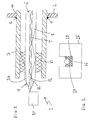
- FIG. 1 shows a schematic diagram of an optical fibre within an optical module housing according to one embodiment of the present invention; and
- FIG. 2 shows a schematic diagram of an optical fibre attached to a metal component according to a second embodiment of the present invention.
-
- Thus, as partly shown in FIG. 1, an optical fibre module 1 has a
housing 2, which may be made of metal. Aprotective tube 3 passes through anaperture 4 in thehousing 2 and is welded to the housing, as shown at 5, the protective tube also being formed of metal. Theprotective tube 3 contains within it an optical fibre 6 having a centraloptical glass core 7 surrounded by aglass cladding 8. Theprotective tube 3 and the optical fibre 6 extend out from the module 1 to the next component that the optical fibre is to be coupled to. This may be some way away, of course, especially if the module 1 forms part of an undersea repeater station. - As is well known, the end 9 of the optical fibre 6 that is within the module 1 is to be aligned with a
semiconductor laser diode 10, such that light is coupled from a lasing portion of thediode 10 into the end face of the optical fibre 6. The end face of the optical fibre 6 is arranged to be tapered, so that as much of the light from the laser diode as possible is coupled into thecentral core 7 of the fibre 6 or into thecladding 8 at an angle such that the light preferably refracts into thecentral core 7 from the core/cladding interface, or at least does not escape from the cladding. One ray oflight 11 is shown entering thecentral core 7 and being reflected from the core/cladding interface to propagate down the core in the desired manner. Anotherlight ray 12 is shown as entering thecladding 8 and reflecting from the core/cladding interface and the exterior of the cladding until it is absorbed by the cladding, as shown by the dotted line. It will be appreciated that the light ray must be incident on the exterior surface of the cladding at a fairly shallow angle in order to reflect off it rather than be transmitted through it. - The optical fibre 6 is fixed and sealed to the
protective tube 3 by aglass joint 13. Theglass joint 13 is made of a glass having a refractive index lower than the refractive index of thecladding 8 of the optical fibre 6, and can provide a hermetic seal between theprotective tube 3 and the optical fibre 6. The cladding usually has a refractive index of about 1.46 and the refractive index of theglass joint 13 is lower than that, preferably about 1.43. By making the glass joint have a refractive index less than that of the cladding, light rays incident on the joint/cladding interface are less likely to be transmitted through the interface and hence into theglass joint 13, and more likely to be reflected off the join/cladding interface back into the cladding. - As shown in FIG. 1, a
light ray 14 entering thecladding 8 from thelaser diode 10 is transmitted through the joint/cladding interface into theglass joint 13 where it is absorbed and converted into heat energy. The heat energy is then conducted through the protective tube to themetal housing 2. By making the glass joint from a glass having a low refractive index, the amount of light reflected from the joint/cladding interface will be increased, thus decreasing the amount of light energy being converted to heat in the joint and being conducted to the housing. By making the refractive index about 1.43, only light rays incident upon the joint/cladding interface at an angle of more than about 20° will be transmitted through the interface. This contrasts to the situation where the refractive index of the glass joint is 1.46 or more, as is presently the case, where light rays at angles of incidence of more than about 11.6° are transmitted through the joint/cladding interface. Glasses with a refractive index as low as 1.43, but still having a melting point sufficiently low to be able to be used to form the joint, are known to be available, for example from Schott Glass Electronic Packaging of Christoph-Dorner Str. 29, D-84028 Landshut, Germany, and known as, for example, FK54, and from Ohara of Nording 30A, D-65719 Hofheim a Ts., Germany and known as, for example, S-FPL53. - A further embodiment of the invention is shown in FIG. 2, where an
optical fibre 16 is shown attached to ametal component 15, such as, for example in an alignment structure. In this case, theoptical fibre 16 is mounted within a groove orchannel 17 in thecomponent 15 and is partly embedded in theglass joint 18 which fills the bottom of thechannel 17. Theglass joint 18 does not provide a hermetic seal, but does fix the fibre in position relative to thecomponent 15. Again, using a glass of low refractive index to form the glass joint limits the amount of light that is transmitted through the joint/cladding interface, so that the amount of heat conducted into themetal component 15 is reduced, compared to previously used glass joints. - It will be appreciated that although only two particular embodiments of the invention have been described in detail, various modifications and improvements can be made by a person skilled in the art without departing from the scope of the present invention.
Claims (8)
- A glass joint (13) for joining an optical fibre (6) including a core (7) and a cladding (8) to an optical module housing (2) at least partly formed of metal, the glass joint being formed from a glass having a refractive index less than that of the cladding (8).
- A glass joint according to claim 1, wherein the refractive index of the glass is less than 1.46.
- A glass joint according to claim 2, wherein the refractive index of the glass is less than about 1.43.
- An optical fibre module (1) comprising an optical fibre (6) including a core (7) and a cladding (8), an optical module housing (2) at least partly formed of metal, and a glass joint (13) joining the optical fibre (6) to the optical module housing (2), the glass joint (13) being as defined in any one of claims 1 to 3.
- An optical fibre module (1) according to claim 4, wherein the glass joint (13) provides a hermetic glass seal between the optical fibre (6) and the optical module housing (2).
- An undersea repeater station incorporating an optical fibre module (1) according to either claim 4 or claim 5.
- A method of joining an optical fibre (6) to an optical module housing (2) comprising the steps of:providing an optical module housing (2) at least partly made of metal;providing an optical fibre (6) having a core (7) and a cladding (8);locating the optical fibre (6) in the housing (2); andjoining the fibre (6) to the housing (2) by means of a glass joint (13) according to any one of claims 1 to 3.
- A method of joining an optical fibre (6) to an optical module housing (2) according to claim 7, wherein the glass joint (13) is a hermetic glass seal.
Priority Applications (1)
| Application Number | Priority Date | Filing Date | Title |
|---|---|---|---|
| EP01307628A EP1291691A1 (en) | 2001-09-07 | 2001-09-07 | Glass joint for an optical fibre module and a method of joining an optical fibre to an optical module housing |
Applications Claiming Priority (1)
| Application Number | Priority Date | Filing Date | Title |
|---|---|---|---|
| EP01307628A EP1291691A1 (en) | 2001-09-07 | 2001-09-07 | Glass joint for an optical fibre module and a method of joining an optical fibre to an optical module housing |
Publications (1)
| Publication Number | Publication Date |
|---|---|
| EP1291691A1 true EP1291691A1 (en) | 2003-03-12 |
Family
ID=8182252
Family Applications (1)
| Application Number | Title | Priority Date | Filing Date |
|---|---|---|---|
| EP01307628A Withdrawn EP1291691A1 (en) | 2001-09-07 | 2001-09-07 | Glass joint for an optical fibre module and a method of joining an optical fibre to an optical module housing |
Country Status (1)
| Country | Link |
|---|---|
| EP (1) | EP1291691A1 (en) |
Cited By (1)
| Publication number | Priority date | Publication date | Assignee | Title |
|---|---|---|---|---|
| US6907179B2 (en) * | 2001-04-07 | 2005-06-14 | Carl Zeiss Jena Gmbh | Device for holding optical components |
Citations (5)
| Publication number | Priority date | Publication date | Assignee | Title |
|---|---|---|---|---|
| US3654401A (en) * | 1969-05-29 | 1972-04-04 | Licentia Gmbh | Playback system with radiation guide member having a slide portion extending into the groove |
| GB2051773A (en) * | 1979-06-12 | 1981-01-21 | Standard Telephones Cables Ltd | Fluorine containing glasses |
| EP0274222A1 (en) * | 1986-12-05 | 1988-07-13 | Bt&D Technologies Limited | Optical fiber feedthrough |
| GB2207254A (en) * | 1987-07-11 | 1989-01-25 | Stc Plc | Glass-clad optical fibre couplers |
| US4904046A (en) * | 1988-03-08 | 1990-02-27 | Schott Glaswerke | Process of and apparatus for leading an optical waveguide through a wall via a hermetic seal |
-
2001
- 2001-09-07 EP EP01307628A patent/EP1291691A1/en not_active Withdrawn
Patent Citations (5)
| Publication number | Priority date | Publication date | Assignee | Title |
|---|---|---|---|---|
| US3654401A (en) * | 1969-05-29 | 1972-04-04 | Licentia Gmbh | Playback system with radiation guide member having a slide portion extending into the groove |
| GB2051773A (en) * | 1979-06-12 | 1981-01-21 | Standard Telephones Cables Ltd | Fluorine containing glasses |
| EP0274222A1 (en) * | 1986-12-05 | 1988-07-13 | Bt&D Technologies Limited | Optical fiber feedthrough |
| GB2207254A (en) * | 1987-07-11 | 1989-01-25 | Stc Plc | Glass-clad optical fibre couplers |
| US4904046A (en) * | 1988-03-08 | 1990-02-27 | Schott Glaswerke | Process of and apparatus for leading an optical waveguide through a wall via a hermetic seal |
Cited By (1)
| Publication number | Priority date | Publication date | Assignee | Title |
|---|---|---|---|---|
| US6907179B2 (en) * | 2001-04-07 | 2005-06-14 | Carl Zeiss Jena Gmbh | Device for holding optical components |
Similar Documents
| Publication | Publication Date | Title |
|---|---|---|
| US5446816A (en) | Optical fiber having a lens formed at an end thereof | |
| US8562195B2 (en) | Fiber optic illumination module with fiber optic coupling | |
| US20070172174A1 (en) | Monolithic mode stripping fiber ferrule/collimator and method of making same | |
| JP2006221165A (en) | Optical fiber terminal and manufacturing method thereof | |
| US20180188457A1 (en) | Optical communication module configured for enhancing optical coupling efficiency | |
| JP3852709B2 (en) | Optical power monitor and manufacturing method thereof | |
| JP2007293298A (en) | Optical input / output end of optical components | |
| WO2020196562A1 (en) | End part structure of optical fiber and semiconductor laser module | |
| KR20050092126A (en) | Lensed fiber having small form factor and method of making same | |
| US20180188458A1 (en) | Optical communication module configured for enhancing optical coupling efficiency | |
| US20030190135A1 (en) | Hermetic waveguide seals and method of making them | |
| US5257335A (en) | Single mode optical fiber device including a short lens optical fiber | |
| JPH0735958A (en) | Parallel transmission module | |
| US7397985B2 (en) | High-power fused collimator and associated methods | |
| EP2230541A1 (en) | Method and system for packaging a high power fibre optic coupler | |
| JPH07168061A (en) | Optical transceiver module | |
| JP4303614B2 (en) | Optical fiber assembly component for light emitting element and light emitting element module using the same | |
| US20030002844A1 (en) | Optical power beam dump | |
| US6161965A (en) | Optical coupling circuit | |
| US6826319B2 (en) | Optical isolator | |
| JPH0232307A (en) | Optical semiconductor element module | |
| JPH02113212A (en) | Waveguide optical module | |
| JP2857526B2 (en) | Optical fiber terminal structure | |
| Kreutzmann | Solder glass-sealing technology for use in packaging of fiber optic sensors | |
| JP2851810B2 (en) | Assembly method of optical semiconductor element module |
Legal Events
| Date | Code | Title | Description |
|---|---|---|---|
| PUAI | Public reference made under article 153(3) epc to a published international application that has entered the european phase |
Free format text: ORIGINAL CODE: 0009012 |
|
| AK | Designated contracting states |
Kind code of ref document: A1 Designated state(s): AT BE CH CY DE DK ES FI FR GB GR IE IT LI LU MC NL PT SE TR Designated state(s): AT BE CH CY DE DK ES FI FR GB GR IE IT LI LU MC NL PT SE TR |
|
| AX | Request for extension of the european patent |
Extension state: AL LT LV MK RO SI |
|
| AKX | Designation fees paid | ||
| REG | Reference to a national code |
Ref country code: DE Ref legal event code: 8566 |
|
| STAA | Information on the status of an ep patent application or granted ep patent |
Free format text: STATUS: THE APPLICATION IS DEEMED TO BE WITHDRAWN |
|
| 18D | Application deemed to be withdrawn |
Effective date: 20030913 |