EP1291688A2 - Optical transmission line and optical communication system - Google Patents
Optical transmission line and optical communication system Download PDFInfo
- Publication number
- EP1291688A2 EP1291688A2 EP02019034A EP02019034A EP1291688A2 EP 1291688 A2 EP1291688 A2 EP 1291688A2 EP 02019034 A EP02019034 A EP 02019034A EP 02019034 A EP02019034 A EP 02019034A EP 1291688 A2 EP1291688 A2 EP 1291688A2
- Authority
- EP
- European Patent Office
- Prior art keywords
- optical fiber
- optical
- transmission line
- dispersion
- optical transmission
- Prior art date
- Legal status (The legal status is an assumption and is not a legal conclusion. Google has not performed a legal analysis and makes no representation as to the accuracy of the status listed.)
- Withdrawn
Links
- 230000003287 optical effect Effects 0.000 title claims abstract description 238
- 230000005540 biological transmission Effects 0.000 title claims abstract description 179
- 238000004891 communication Methods 0.000 title claims abstract description 55
- 239000013307 optical fiber Substances 0.000 claims abstract description 290
- 239000006185 dispersion Substances 0.000 claims abstract description 243
- 238000005253 cladding Methods 0.000 claims description 27
- 230000001902 propagating effect Effects 0.000 claims description 16
- VYPSYNLAJGMNEJ-UHFFFAOYSA-N Silicium dioxide Chemical compound O=[Si]=O VYPSYNLAJGMNEJ-UHFFFAOYSA-N 0.000 claims description 6
- 230000010287 polarization Effects 0.000 claims description 5
- 235000012239 silicon dioxide Nutrition 0.000 claims description 3
- 238000007526 fusion splicing Methods 0.000 abstract description 4
- 238000011144 upstream manufacturing Methods 0.000 abstract description 3
- 230000001186 cumulative effect Effects 0.000 description 55
- 230000015556 catabolic process Effects 0.000 description 24
- 238000006731 degradation reaction Methods 0.000 description 24
- 230000007423 decrease Effects 0.000 description 11
- 238000001069 Raman spectroscopy Methods 0.000 description 4
- 230000003321 amplification Effects 0.000 description 4
- 238000003199 nucleic acid amplification method Methods 0.000 description 4
- PXGOKWXKJXAPGV-UHFFFAOYSA-N Fluorine Chemical compound FF PXGOKWXKJXAPGV-UHFFFAOYSA-N 0.000 description 3
- 229910052731 fluorine Inorganic materials 0.000 description 3
- 239000011737 fluorine Substances 0.000 description 3
- 239000000463 material Substances 0.000 description 3
- 230000003467 diminishing effect Effects 0.000 description 2
- 239000000835 fiber Substances 0.000 description 2
- YBMRDBCBODYGJE-UHFFFAOYSA-N germanium dioxide Chemical compound O=[Ge]=O YBMRDBCBODYGJE-UHFFFAOYSA-N 0.000 description 2
- 238000000034 method Methods 0.000 description 2
- 238000012986 modification Methods 0.000 description 2
- 230000004048 modification Effects 0.000 description 2
- ZAMOUSCENKQFHK-UHFFFAOYSA-N Chlorine atom Chemical compound [Cl] ZAMOUSCENKQFHK-UHFFFAOYSA-N 0.000 description 1
- 238000013459 approach Methods 0.000 description 1
- 238000005452 bending Methods 0.000 description 1
- 229910052801 chlorine Inorganic materials 0.000 description 1
- 239000000460 chlorine Substances 0.000 description 1
- 238000013461 design Methods 0.000 description 1
- 239000012535 impurity Substances 0.000 description 1
- 230000002401 inhibitory effect Effects 0.000 description 1
- 238000004904 shortening Methods 0.000 description 1
Images







Classifications
-
- G—PHYSICS
- G02—OPTICS
- G02B—OPTICAL ELEMENTS, SYSTEMS OR APPARATUS
- G02B6/00—Light guides; Structural details of arrangements comprising light guides and other optical elements, e.g. couplings
- G02B6/02—Optical fibres with cladding with or without a coating
- G02B6/02004—Optical fibres with cladding with or without a coating characterised by the core effective area or mode field radius
- G02B6/02009—Large effective area or mode field radius, e.g. to reduce nonlinear effects in single mode fibres
- G02B6/02014—Effective area greater than 60 square microns in the C band, i.e. 1530-1565 nm
- G02B6/02019—Effective area greater than 90 square microns in the C band, i.e. 1530-1565 nm
-
- G—PHYSICS
- G02—OPTICS
- G02B—OPTICAL ELEMENTS, SYSTEMS OR APPARATUS
- G02B6/00—Light guides; Structural details of arrangements comprising light guides and other optical elements, e.g. couplings
- G02B6/02—Optical fibres with cladding with or without a coating
- G02B6/02214—Optical fibres with cladding with or without a coating tailored to obtain the desired dispersion, e.g. dispersion shifted, dispersion flattened
- G02B6/02219—Characterised by the wavelength dispersion properties in the silica low loss window around 1550 nm, i.e. S, C, L and U bands from 1460-1675 nm
- G02B6/02247—Dispersion varying along the longitudinal direction, e.g. dispersion managed fibre
-
- G—PHYSICS
- G02—OPTICS
- G02B—OPTICAL ELEMENTS, SYSTEMS OR APPARATUS
- G02B6/00—Light guides; Structural details of arrangements comprising light guides and other optical elements, e.g. couplings
- G02B6/02—Optical fibres with cladding with or without a coating
- G02B6/036—Optical fibres with cladding with or without a coating core or cladding comprising multiple layers
- G02B6/03605—Highest refractive index not on central axis
- G02B6/03611—Highest index adjacent to central axis region, e.g. annular core, coaxial ring, centreline depression affecting waveguiding
-
- G—PHYSICS
- G02—OPTICS
- G02B—OPTICAL ELEMENTS, SYSTEMS OR APPARATUS
- G02B6/00—Light guides; Structural details of arrangements comprising light guides and other optical elements, e.g. couplings
- G02B6/02—Optical fibres with cladding with or without a coating
- G02B6/036—Optical fibres with cladding with or without a coating core or cladding comprising multiple layers
- G02B6/03616—Optical fibres characterised both by the number of different refractive index layers around the central core segment, i.e. around the innermost high index core layer, and their relative refractive index difference
- G02B6/03622—Optical fibres characterised both by the number of different refractive index layers around the central core segment, i.e. around the innermost high index core layer, and their relative refractive index difference having 2 layers only
- G02B6/03627—Optical fibres characterised both by the number of different refractive index layers around the central core segment, i.e. around the innermost high index core layer, and their relative refractive index difference having 2 layers only arranged - +
-
- G—PHYSICS
- G02—OPTICS
- G02B—OPTICAL ELEMENTS, SYSTEMS OR APPARATUS
- G02B6/00—Light guides; Structural details of arrangements comprising light guides and other optical elements, e.g. couplings
- G02B6/02—Optical fibres with cladding with or without a coating
- G02B6/036—Optical fibres with cladding with or without a coating core or cladding comprising multiple layers
- G02B6/03616—Optical fibres characterised both by the number of different refractive index layers around the central core segment, i.e. around the innermost high index core layer, and their relative refractive index difference
- G02B6/03638—Optical fibres characterised both by the number of different refractive index layers around the central core segment, i.e. around the innermost high index core layer, and their relative refractive index difference having 3 layers only
- G02B6/03644—Optical fibres characterised both by the number of different refractive index layers around the central core segment, i.e. around the innermost high index core layer, and their relative refractive index difference having 3 layers only arranged - + -
-
- G—PHYSICS
- G02—OPTICS
- G02B—OPTICAL ELEMENTS, SYSTEMS OR APPARATUS
- G02B6/00—Light guides; Structural details of arrangements comprising light guides and other optical elements, e.g. couplings
- G02B6/24—Coupling light guides
- G02B6/26—Optical coupling means
- G02B6/28—Optical coupling means having data bus means, i.e. plural waveguides interconnected and providing an inherently bidirectional system by mixing and splitting signals
- G02B6/293—Optical coupling means having data bus means, i.e. plural waveguides interconnected and providing an inherently bidirectional system by mixing and splitting signals with wavelength selective means
- G02B6/29371—Optical coupling means having data bus means, i.e. plural waveguides interconnected and providing an inherently bidirectional system by mixing and splitting signals with wavelength selective means operating principle based on material dispersion
- G02B6/29374—Optical coupling means having data bus means, i.e. plural waveguides interconnected and providing an inherently bidirectional system by mixing and splitting signals with wavelength selective means operating principle based on material dispersion in an optical light guide
- G02B6/29376—Optical coupling means having data bus means, i.e. plural waveguides interconnected and providing an inherently bidirectional system by mixing and splitting signals with wavelength selective means operating principle based on material dispersion in an optical light guide coupling light guides for controlling wavelength dispersion, e.g. by concatenation of two light guides having different dispersion properties
- G02B6/29377—Optical coupling means having data bus means, i.e. plural waveguides interconnected and providing an inherently bidirectional system by mixing and splitting signals with wavelength selective means operating principle based on material dispersion in an optical light guide coupling light guides for controlling wavelength dispersion, e.g. by concatenation of two light guides having different dispersion properties controlling dispersion around 1550 nm, i.e. S, C, L and U bands from 1460-1675 nm
-
- H—ELECTRICITY
- H04—ELECTRIC COMMUNICATION TECHNIQUE
- H04B—TRANSMISSION
- H04B10/00—Transmission systems employing electromagnetic waves other than radio-waves, e.g. infrared, visible or ultraviolet light, or employing corpuscular radiation, e.g. quantum communication
- H04B10/25—Arrangements specific to fibre transmission
- H04B10/2507—Arrangements specific to fibre transmission for the reduction or elimination of distortion or dispersion
- H04B10/2513—Arrangements specific to fibre transmission for the reduction or elimination of distortion or dispersion due to chromatic dispersion
- H04B10/2525—Arrangements specific to fibre transmission for the reduction or elimination of distortion or dispersion due to chromatic dispersion using dispersion-compensating fibres
- H04B10/25253—Arrangements specific to fibre transmission for the reduction or elimination of distortion or dispersion due to chromatic dispersion using dispersion-compensating fibres with dispersion management, i.e. using a combination of different kind of fibres in the transmission system
-
- H—ELECTRICITY
- H04—ELECTRIC COMMUNICATION TECHNIQUE
- H04B—TRANSMISSION
- H04B10/00—Transmission systems employing electromagnetic waves other than radio-waves, e.g. infrared, visible or ultraviolet light, or employing corpuscular radiation, e.g. quantum communication
- H04B10/29—Repeaters
- H04B10/291—Repeaters in which processing or amplification is carried out without conversion of the main signal from optical form
- H04B10/2912—Repeaters in which processing or amplification is carried out without conversion of the main signal from optical form characterised by the medium used for amplification or processing
- H04B10/2916—Repeaters in which processing or amplification is carried out without conversion of the main signal from optical form characterised by the medium used for amplification or processing using Raman or Brillouin amplifiers
-
- H—ELECTRICITY
- H04—ELECTRIC COMMUNICATION TECHNIQUE
- H04B—TRANSMISSION
- H04B2210/00—Indexing scheme relating to optical transmission systems
- H04B2210/003—Devices including multiple stages, e.g., multi-stage optical amplifiers or dispersion compensators
Definitions
- the present invention relates to an optical transmission line for transmitting signal light, and to an optical communication system including the same.
- the optical communication system is used for transmitting information by transmitting signal light through an optical transmission line, and is capable of transmitting a large capacity of information.
- it is important to suppress the degradation of a signal. From this viewpoint, it is desirable that the overall dispersion of an optical transmission line has a small absolute value even in the case of a long transmission distance. It is also desirable that the optical transmission line be subject to less non-linear optical phenomena.
- a standard single-mode optical fiber used as an optical transmission line has a zero dispersion wavelength in the vicinity of a wavelength of 1.3 ⁇ m, and has a chromatic dispersion of about +17 ps/nm/km with a dispersion slope thereof being positive, in the vicinity of a wavelength of 1.55 ⁇ m, which is the signal light wavelength thereof. Therefore, forming the optical transmission line in a relay section using single-mode optical fibers alone would not allow the optical transmission line to have a small absolute value of cumulative dispersion for a long transmission distance. Under such circumstances, various proposals have hitherto been made for optical transmission lines having a small absolute value of the cumulative dispersion even in the case of a long transmission distance.
- Japanese Unexamined Patent Application Publication No. 11-355206 and US Patent Nos. 5,778,128, 5,611,016, and 6,178,279 each disclose an optical transmission line (related art 1) in which a positive-dispersion optical fiber and a negative-dispersion optical fiber are connected in series or they are alternately connected.
- US Patent No. 6,084,993 discloses an optical transmission line (related art 2) that has a configuration in which a non-linearity diminishing optical fiber with a large effective area, a dispersion adjusted transmission optical fiber with a small negative chromatic dispersion, and an optical fiber for diminishing and adjusting a dispersion slope, which is used to adjust the overall dispersion slope, are connected in this order.
- US Patent No. 5,995,694 discloses an optical transmission line (related art 3) that has a configuration in which a standard single-mode optical fiber, a dispersion compensation optical fiber, of which the chromatic dispersion and the dispersion slope are both negative, and a dispersion flat optical fiber with a dispersion slope of a small absolute value, are connected in this order.
- US Patent No. 5,894,537 discloses an optical transmission line (related art 4), which is a so-called "dispersion managed optical fiber".
- the dispersion managed optical fiber is formed such that positive dispersion regions each having a positive chromatic dispersion, and negative dispersion regions each having a negative chromatic dispersion are alternately disposed along the longitudinal direction thereof.
- the optical transmission line according to the present invention comprises a first optical fiber having an effective area not smaller than 80 ⁇ m 2 at a wavelength of 1550 nm and a second optical fiber connected to the first optical fiber, the second optical fiber having at least one positive dispersion region in which the chromatic dispersion is positive and at least one negative dispersion region in which the chromatic dispersion is negative, along the longitudinal direction thereof at a predetermined wavelength in a signal wavelength band, respectively.
- the first optical fiber may have a core formed of substantially pure silica glass.
- the effective area of the first optical fiber may be not less than 100 ⁇ m 2 , and the overall dispersion thereof may be not more than 400 ps/nm.
- the transmission loss of the first optical fiber may be not more than 0.25 dB/km, and the transmission loss thereof may be less than that of the second optical fiber.
- the absolute value of a dispersion slope in the positive dispersion region may be 0.04 ps/nm 2 /km or below, and the absolute value of a dispersion slope in the negative dispersion region may be 0.04 ps/nm 2 /km or below, as well.
- the absolute value of the overall dispersion of the second optical fiber may be 100 ps/nm or below, and the absolute value of the average chromatic dispersion thereof may be 5 ps/nm/km or below.
- positive dispersion regions and negative dispersion regions may be alternately arranged along the longitudinal direction thereof.
- the chromatic dispersion in the at least one positive dispersion region may be 5 ps/nm/km or more, and its length may be 5 km or below.
- the absolute value of the chromatic dispersion in the at least one negative dispersion region may be 5 ps/nm/km or above, and its length may be 5 km or below.
- the average chromatic dispersion in the at least one positive dispersion region may be 4 ps/nm/km or more, and the absolute value of the average chromatic dispersion in the at least one negative dispersion region may be 4 ps/nm/km or above.
- the negative dispersion region may be connected to the first optical fiber.
- the second optical fiber may comprise a core having a first refractive index, a first cladding having a second refractive index lower than the first refractive index, and a second cladding surrounding the first cladding and having a third refractive index higher than the second refractive index.
- the second optical fiber may further comprise a third cladding surrounding the second cladding and having a fourth refractive index lower than the third refractive index.
- the second optical fiber may comprise a first core including an optical axis at the center thereof and having a first refractive index, a second core surrounding the first core and having a second refractive index higher than the first refractive index, and a cladding having a third refractive index lower than the second refractive index.
- the second optical fiber may further comprise a second cladding surrounding the first cladding and having a fourth refractive index higher than the third refractive index.
- the optical transmission line according to the present invention may be arranged so that the polarization mode dispersion thereof is not more than 0.2 ps/km 1/2 at the predetermined wavelength. Also, the present optical transmission line may be arranged such that the first optical fibers are connected to both ends of the second optical fiber.
- the optical transmission line according to the present invention may further comprise a dispersion compensator for reducing the absolute values of the chromatic dispersions of both the first and second optical fibers at a predetermined wavelength.
- the present optical transmission line may further comprise a third optical fiber provided for reducing the absolute values of the chromatic dispersions of both the first and second optical fibers at the predetermined wavelength.
- this third optical fiber may have a chromatic dispersion of -30 ps/nm/km or less and an effective area of 15 ⁇ m 2 or above.
- the absolute value of the overall dispersion of the present optical transmission line may be not more than 100 ps/km at the predetermined wavelength.
- the present invention provides an optical communication system which includes the optical transmission line according to the present invention, and in which an optical communication is performed by transmitting signal light through a first optical fiber, a second optical fiber (and furthermore, a third optical fiber) of the above-described optical transmission line, in this order.
- the optical communication system according to the present invention may further comprise pump light supplying means that supplies pump light propagating in the direction opposite to the propagating direction of the signal light in the optical transmission line. By supplying the pump light to the optical transmission line by the pump light supplying means, the signal light may be Raman-amplified in the optical transmission line.
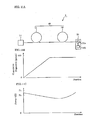
- Figures 1A to 1C illustrate the optical communication system 1 and the optical transmission line 10 according to the first embodiment.
- Fig. 1A shows the configuration of the optical communication system 1
- Fig. 1B shows the cumulative dispersion at each position of the optical transmission line 10
- Fig. 1C shows the signal light power at each position of the optical transmission line 10.
- the optical communication system 1 has a configuration in which the optical transmission line 10 is laid between a repeater (or transmitter) 14 and a repeater (or receiver) 15.
- the optical transmission line 10 is formed by fusion-splicing a first optical fiber 11 and a second optical fiber 12 that are arranged in this order from the upstream side to the downstream side.
- the optical fiber 11 has an effective area of 80 ⁇ m 2 or above, and preferably 100 ⁇ m 2 or above. Also, the optical fiber 11 preferably has a transmission loss of 0.25 dB/km or less at the signal light wavelength thereof. That is, the optical fiber 11 is of a low-loss and low non-linearity type.
- the optical fiber 11 is a single-mode optical fiber having its zero dispersion wavelength in the vicinity of a wavelength of 1.3 ⁇ m, and having a chromatic dispersion of about 17 to 20 ps/nm/km in the vicinity of the signal light wavelength of 1.55 ⁇ m.
- the optical fiber 12 is connected to the downstream end of the optical fiber 11, and has at least one positive dispersion region in which the chromatic dispersion is positive and at least one negative dispersion region in which the chromatic dispersion is negative, respectively along the longitudinal direction at the wavelength of 1550 nm.
- Figures. 1A to 1C show an example in the case of a dispersion-managed optical fiber.
- Fig. 1B there are differences between the optical fiber 11 section and the optical fiber 12 section in the cumulative dispersion from the incident position 16 to each position on the optical transmission line 10. Specifically, in the optical fiber 11 section, where the chromatic dispersion thereof is constant, the cumulative dispersion gradually increases with an increase in the propagation distance from the incident position 16. On the other hand, in the optical fiber 12 section, where positive dispersion regions and negative dispersion regions are alternately arranged, the change in the cumulative dispersion thereof is small.
- the signal light power at each position on the optical transmission line 10 gradually decreases in both the optical fiber 11 and 12 sections.
- the optical fiber 11 has a lower loss than the optical fiber 12.
- a predetermined wavelength e.g., 1550 nm
- a signal wavelength band a portion of a wavelength range of 1250 nm to 1700 nm
- the occurrence of non-linear optical phenomena such as four-wave mixing is also relatively rare, since the power of the propagating signal light is relatively low, and the absolute value of the chromatic dispersion of each of the positive and negative dispersion regions of the optical fiber 12 is relatively large.
- the occurrence of non-linear optical phenomena is reduced over the entire optical transmission line 10, and accordingly signal degradation is suppressed.
- the power of the signal light at the incident position 16 is set to a predetermined power P 1 or less so that the degree of signal degradation due to non-linear optical phenomena in the optical fiber 11 falls within a tolerable range.
- the signal light emitted from the optical fiber 11 is designed to have a predetermined power P 2 or less when the signal light is incident upon the optical fiber 12, by adjusting the length of the optical fiber 11, so that the degree of signal degradation due to non-linear optical phenomena in the optical fiber 12 falls within a tolerable range.
- the overall dispersion of the optical fiber 11 be not more than 400 ps/nm at a wavelength of 1550 nm.
- Figure 2 shows a refractive index profile of the optical fiber 11.
- the illustrated optical fiber 11 having a refractive index profile 21 comprises a core 22 including an optical axis at the center thereof and having a refractive index of n 1 , and a cladding 23 surrounding the core 22 and having a refractive index of n 2 .
- n 1 > n 2 .
- the optical fiber 11 is formed by using silica glass as a base material and adding germanium oxide (GeO 2 ) to the core 22, or by using substantially pure silica glass (a trace quantity of impurities such as chlorine may be contained) for the core 22 and adding fluorine to the cladding 23. Comparing the above-described two forming methods, the latter allows a relatively longer transmission distance and higher power of the incident signal light, since transmission loss and non-linearity are lower in the case of the latter.
- the optical fiber 11 has a transmission loss of 0.25 dB/km or less, which is lower than that of the optical fiber 12.
- the optical fiber 11 has an effective area not smaller than 80 ⁇ m 2 , and preferably, not smaller than 100 ⁇ m 2 . As the effective area increases, the non-linearity decreases, and thereby degradation of the signal light waveform due to non-linear optical phenomena can be reduced, which allows an increase in the power of incident signal light.
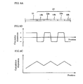
- Figures 3A to 3C illustrate the optical fiber 12.
- Fig. 3A shows the outline of the optical fiber 12
- Fig. 3B shows the chromatic dispersion at each position of the optical fiber 12
- Fig. 3C shows the cumulative dispersion at each position of the optical fiber 12.
- the optical fiber 12 has a configuration in which a positive dispersion region 12a having a positive chromatic dispersion D A at the wavelength of 1550 nm, and a negative dispersion region 12b having a negative chromatic dispersion D B at the wavelength of 1550 nm are alternately arranged.
- the cumulative dispersion of the optical fiber 12 repeats its increase and decrease in the longitudinal direction. Therefore, if each of the positive and negative dispersion regions 12a and 12b is long and the absolute value of each of the chromatic dispersions D A and D B is large, the cumulative dispersion of the optical fiber 12 may possibly fall outside a tolerable range, depending on the position. Accordingly, it would be preferable that the product of the length of the positive dispersion region 12a and the chromatic dispersion D A do not become significantly large. Conversely, if the chromatic dispersion D A is too low, non-linear degradation tends to occur, and hence, the chromatic dispersion D A should be designed to have a value over a certain degree.
- the chromatic dispersion D A of the positive dispersion region 12a is +17 ps/nm/km
- the chromatic dispersion D B of the negative dispersion region 12b is -17 ps/nm/km, that is, the length ratio between the positive dispersion region 12a and the negative dispersion region 12b is 1:1.
- the chromatic dispersion D A is +4 ps/nm/km
- the chromatic dispersion D B is -4 ps/nm/km, that is, the length ratio therebetween is 1:1.
- the chromatic dispersion D A is +8 ps/nm/km, and the chromatic dispersion D B is -32 ps/nm/km, that is, the length ratio is 4:1. Even more alternatively, the chromatic dispersion D A is +4 ps/nm/km, and the chromatic dispersion D B is -40 ps/nm/km, that is, the length ratio D B /D A is 10:1.
- Figure 4 shows a refractive index profile of the optical fiber 12.
- the illustrated optical fiber 12 having a refractive index profile 41 comprises a core 42 with a refractive index of n 1 , a first cladding 43 with a refractive index of n 2 , and a second cladding 44 surrounding the first cladding 43 and having a refractive index of n 3 .
- the optical fiber 12 is formed by using silica glass as a base material, and for example, by adding GeO 2 to the core 42, as well as adding fluorine to the first cladding 43.
- Figure 5 shows another refractive index profile of the second optical fiber 12.
- the illustrated optical fiber 12 having a refractive index profile 51 further comprises a third cladding 45 having a refractive index of n 4 and formed outside the refractive index profile 41 shown in Fig. 4.
- Figure 6 shows still another refractive index profile of the second optical fiber 12.
- the illustrated optical fiber 12 having a refractive index profile 61 comprises a first core 62 including the center of the optical axis and having a refractive index of n 1 , a second core 63 surrounding the first core 62 and having a refractive index of n 2 , and a cladding (first Cladding) 64 having a refractive index of n 3 .
- n 2 > n 1
- n 2 > n 3 .
- the optical fiber 12 is formed by using silica glass as a base material, and for example, by adding GcO 2 to the second core 63, as well as adding fluorine to the first core 62.
- Figure 7 shows a further example of a refractive index profile of the second optical fiber 12.
- the illustrated optical fiber 12 having a refractive index profile 71 comprises a second cladding 65 having a refractive index of n 4 and formed outside the first cladding 64 of the refractive index profile 61 shown in Fig. 6.
- the optical fiber 12 having a refractive index profile shown in any of Figs. 4 to 7 is desirable for reducing the absolute value of a dispersion slope and reducing the bending loss.
- the optical fiber 12 can be designed to have a positive chromatic dispersion as well as a negative one by adjusting its outer diameter.
- an optical fiber 12 in which positive and negative dispersion regions 12a and 12b are alternately arranged along the longitudinal direction can be produced by the following method: an optical fiber preform in which the outer diameter of each region is constant along the longitudinal direction thereof is prepared, and when this optical fiber preform is drawn into the optical fiber 12, the outer diameter of the fiber is made different between the positive dispersion region 12a and the negative dispersion region 12b.
- the absolute value of the dispersion slope in each of the positive and negative dispersion regions 12a and 12b of the optical fiber 12 is not higher than 0.04 ps/nm 2 /km at a wavelength of 1550 nm. This enables the optical transmission line 10 to transmit multi-wavelength signal light in a broad band, thereby increasing transmission capacity.
- the absolute value of the overall dispersion of the optical fiber 12 be not higher than 100 ps/nm at a wavelength of 1550 nm. It is also preferable that the absolute value of the overall average chromatic dispersion of the optical fiber 12 be not higher than 5 ps/nm/km at a wavelength of 1550 nm. In either case, even if the cumulative dispersion at each position on the optical transmission line 10 exceeds the overall dispersion of the optical fiber 11, the excess amount is negligible. This allows the upper limit of the cumulative dispersion to be reduced over the entire optical transmission line 10, thereby suppressing the signal degradation due to the cumulative dispersion.
- the optical fiber 12 be arranged so that positive dispersion regions 12a and negative dispersion regions 12b are alternately disposed along the longitudinal direction thereof.
- the cumulative dispersion at each position of the optical transmission line 10 gradually increases in the optical fiber 11 section and alternately and repeatedly increases and decreases in the optical fiber 12 section. Even if the cumulative dispersion at each position on the optical transmission line 10 exceeds the overall dispersion of the optical fiber 11, the excess amount is negligible. This enables the upper limit of the cumulative dispersion to be reduced over the entire optical transmission line 10, thereby inhibiting the signal degradation due to the cumulative dispersion.
- the optical fiber 12 is arranged such that the chromatic dispersion in each of the positive dispersion region 12a and negative dispersion regions 12b is not less than 5 ps/nm/km at the wavelength of 1550 nm and their respective length is not more than 5 km. Also, preferably, the optical fiber is arranged so that the absolute value of the average chromatic dispersion in each of the positive and negative dispersion regions 12a and 12b is not lower than 4 ps/nm/km at a wavelength of 1550 nm. In these cases, the signal degradation due to non-linear phenomena in the optical fiber 12 can be suppressed.
- a negative dispersion region 12b included in the optical fiber 12 be connected to the optical fiber 11.
- the case where the negative dispersion region 12b is connected to the optical fiber 11 allows the upper limit of the cumulative dispersion at each position of the optical fiber 12 to become low as compared with a case where the positive dispersion region 12a is connected to the optical fiber 11.
- the polarization mode dispersion of the optical transmission line 10 is not more than 0.2 ps/km 1/2 at a wavelength of 1550 nm.
- the optical communication system 1 is capable of high-speed transmission with a bit rate of 10 GB/s or above.
- a dispersion compensator having a chromatic dispersion whose sign is different from that of the first optical fiber 11 is provided in the repeater 15 so that the dispersion compensator compensates the chromatic dispersion of the optical transmission line 10.
- the absolute value of the overall dispersion of the optical transmission line 10 including the dispersion compensator is not more than 100 ps/km at a wavelength of 1550 nm. In this manner, providing a dispersion compensator in the repeater or the like reduces the absolute value of the overall chromatic dispersion of the optical transmission line and thereby suppresses signal degradation due to the cumulative dispersion.
- the optical transmission line and the optical communication system according to the present invention have a long transmission distance, and are superior in the transmission quality of signal light, and hence, they have the advantage over the related arts 1 to 4. Reducing the power of the signal light emitted from a repeater (or transmitter) to the optical transmission line would eliminate the above-described problems. However, this would involve shortening the transmission distance, resulting in an increased number of repeaters and consequently an increased cost of the optical communication system.
- Figures 9A to 9C illustrate an optical communication system 2 and an optical transmission line 20 according to the second embodiment.
- Fig. 9A shows the configuration of the optical communication system 2
- Fig. 9B shows the cumulative dispersion at each position on the optical transmission line 20
- Fig. 9C shows the signal light power at each position on the optical transmission line 20.
- Fig. 9B macroscopically exhibits a longitudinal distribution of the cumulative dispersion, as in the case of Fig. 1B.
- the optical communication system 2 has a configuration in which the optical transmission line 20 is laid between the repeater (or transmitter) 14 and the repeater (or receiver) 15.
- the optical transmission line 20 is formed by fusion-splicing the first optical fiber 11, the second optical fiber 12, and a third optical fiber 13 that are arranged in this order from the upstream side to the downstream side.
- the optical fibers 11 and 12, and the repeaters 14 and 15 in this embodiment are each the same ones as those used in the above described first embodiment.
- the second embodiment is different from the first embodiment in that the optical communication system 2 and the optical transmission line 20 according to the second embodiment are further provided with the optical fiber 13.
- the third optical fiber 13 is connected to the downstream end of the optical fiber 12, and at a wavelength of 1550 nm, the third optical fiber 13 has a chromatic dispersion whose sign is different from that of the optical fiber 11. It is preferable that, at a wavelength of 1550 nm, the optical fiber 13 has a chromatic dispersion of -30 ps/nm/km or less and an effective area of 15 ⁇ m 2 or above.
- the cumulative dispersion from the incident position 16 on the optical transmission line 20 to each position thereon varies among the optical fiber 11 section, the optical fiber 12 section, and the optical fiber 13 section.
- the cumulative dispersion gradually increases with an increase in the propagation distance from the incident position 16, and the change in the cumulative dispersion is small in the optical fiber 12 section.
- the cumulative dispersion gradually decreases with an increase in the propagation distance from the incident position 16. In this manner providing the optical fiber 13 reduces the absolute value of the overall dispersion of the optical transmission line 20.
- By appropriately setting the ratio of lengths among these optical fibers it is possible to cause the overall dispersion of the optical transmission line 20 to approach zero.
- the signal light power at each position on the optical transmission line 20 gradually decreases in any of the optical fiber 11 section, the optical fiber 12 section, and the optical fiber 13 section.
- the optical fiber 12 has a lower loss than the optical fiber 13
- the optical fiber 11 has a lower loss than the optical fiber 12.
- the signal light emitted from the repeater 14 propagates through the optical fiber 11, the optical fiber 12, and the optical fiber 13 in this order, and reaches the repeater 15.
- the occurrence of non-linear optical phenomena in the optical fibers 11 and 12, such as four-wave mixing is low.
- the power of the signal light propagating through the optical fiber 13 is lower than that of the signal light propagating through the optical fibers 11 and 12, and therefore, in the optical fiber 13 also, the occurrence of non-linear optical phenomena such as four-wave mixing is low even if the optical fiber 13 has a high non-linearity.
- non-linear optical phenomena are reduced over the entire optical transmission line 20, and thereby signal degradation due to non-linear optical phenomena is suppressed.
- the power of signal light at the incident position 16, and the power of signal light emitted from the optical fiber 11 and incident upon the optical fiber 12 are designed to be the predetermined powers P 1 and P 2 or less, respectively, so that the degree of the signal degradation due to non-linear optical phenomena in the optical fiber 12 falls within a tolerable range, as in the case of the first embodiment.
- the power of the signal light emitted from the optical fiber 12 and incident upon the optical fiber 13 is designed to be a predetermined powers P 3 or less so that the degree of signal degradation due to non-linear optical phenomena in the optical fiber 13 falls within a tolerable range.
- the length of the optical fiber 11 is set such that the power of the signal light outputted from the optical fiber 11 and inputted into the optical fiber 12 becomes the predetermined power P 2 or less. Also, the length of each of the optical fibers 11 and 12 is set such that the power of the signal light outputted from the optical fiber 12 and inputted into the optical fiber 13 becomes the predetermined power P 3 or less.
- the cumulative dispersion at each position of the optical transmission line 20 gradually increases in the optical fiber 11 section, and the change in the cumulative dispersion is small in the optical fiber 12 section.
- the change in the cumulative dispersion thereof is small.
- the optical fiber 13 section the cumulative dispersion thereof gradually decreases. Even if the cumulative dispersion at each position on the optical transmission line 20 exceeds the overall dispersion of the optical fiber 11, the excess amount is negligible. This makes it possible to reduce the upper limit of the cumulative dispersion over the entire optical transmission line 20, thereby suppressing the signal degradation due to the cumulative dispersion. From this viewpoint, it is preferable that the overall dispersion of the optical fiber 11 be not more than 400 ps/nm at a wavelength of 1550 nm.
- providing the third optical fiber 13 reduces the absolute value of the overall chromatic dispersion of the optical transmission line 20, and thereby the signal degradation due to the cumulative dispersion is suppressed.
- the polarization mode dispersion of the optical transmission line 20 is not more than 0.2 ps/km 1/2 at a wavelength of 1550 nm.
- the optical communication system 2 is capable of high-speed transmission with a bit rate of 10 GB/s or above.
- the optical fiber 13 has a chromatic dispersion of -30 ps/nm/km or less and an effective area of 15 ⁇ m 2 or above.
- a high absolute value of the chromatic dispersion allows the length of the optical fiber 13 to be reduced, and a large effective area enables the non-linearity to be reduced.
- the absolute value of the overall dispersion of the optical transmission line 20 is not more than 100 ps/km at a wavelength of 1550 nm.
- Figures 10A and 10B illustrate an optical communication system 3 and an optical transmission line 30 according to the third embodiment.
- Fig. 10A shows the configuration of the optical communication system 3
- Fig. 10B shows the signal light power at each position on the optical transmission line 30.
- the optical communication system 3 has a configuration in which the optical transmission line 30 is laid between the repeater (or transmitter, or alternatively receiver) 14 and a repeater (or receiver, or alternatively transmitter) 15.
- the optical transmission line 30 is formed by fusion-splicing the first optical fiber 11a, the second optical fiber 12, and again the first optical fiber 11b that are arranged in this order from the repeater 14 to the repeater 15.
- the optical fiber 11a and the optical fiber 11b in this embodiment are the same ones as the above-described optical fiber 11.
- the optical fiber 12, and the repeaters 14 and 15 are each the same ones as the above-described ones.
- the optical communication system 3 and the optical transmission line 30 according to this embodiment are different from those of the first embodiment in that the first optical fibers 11a and 11b are connected to both ends of the second optical fiber 12.
- the cumulative dispersion from the position 16, where the signal light emitted from the repeater 14 is launched into the optical transmission line 30, to each position of the optical transmission line 30 varies among the optical fiber 11a section, the optical fiber 12 section, and the optical fiber 11b section. Specifically, in the optical fiber 11a section, the cumulative dispersion gradually increases with an increase in the propagation distance from the incident position 16. On the other hand, in the optical fiber 12 section, the change in the cumulative dispersion thereof is small irrespective of the position. In the optical fiber 11b section, the cumulative dispersion gradually increases with an increase in the propagation distance from the incident position 16.
- the signal light power at each position on the optical transmission line 30 gradually decreases in any of the optical fiber 11a section, the optical fiber 12 section, and the optical fiber 11b section. In general, however, each of the optical fibers 11a and 11b has a lower loss than the optical fiber 12.
- the signal light emitted from the repeater 14 propagates through the optical fiber 11a, the optical fiber 12, and the optical fiber 11b in this order, and reaches the repeater 15.
- the occurrence of non-linear optical phenomena in the optical fibers 11a and 11b such as four-wave mixing, is low.
- the power of the signal light propagating through the optical fiber 11b is lower than that of the signal light propagating through the optical fiber 11a and 12, and hence, in the optical fiber 11b also, the occurrence of non-linear optical phenomena such as four-wave mixing is low.
- the occurrence of non-linear optical phenomena is low over the entire optical transmission line 30, thereby suppressing signal degradation caused by the occurrence of non-linear optical phenomena.
- the signal light emitted from the repeater 15 propagates through the optical fiber 11b, the optical fiber 12, and the optical fiber 11a in this order, and reaches the repeater 14.
- the signal light propagates from the repeater 15 to the repeater 14 also, as in the case where the signal light propagates from the repeater 14 to the repeater 15, non-linear optical phenomena is reduced over the entire optical transmission line 30 and signal degradation due to non-linear optical phenomena is suppressed accordingly.
- this optical transmission line enables bi-directional transmission.
- the power of the signal light at the incident position 16 is arranged to be the predetermined power P 1 or less so that the degree of the signal degradation caused by the occurrence of non-linear optical phenomena in the optical fiber 11a falls within a tolerable range.
- the power of the signal light emitted from the optical fiber 11a and incident upon the optical fiber 12 is designed to be a predetermined power P 2 or less so that the degree of the signal degradation due to non-linear optical phenomena in the optical fiber 12 falls within a tolerable range.
- the power of the signal light emitted from the optical fiber 12 and incident upon the optical fiber 11b presents no problem since it has already become P 1 or below under normal conditions.
- the length of the optical fiber 11 is set such that the power of the signal light outputted from the optical fiber 11a and inputted into the optical fiber 12 becomes the predetermined power P 2 or less.
- the power management described above becomes complicated, and hence, special attention should be given to the design and management of the length of an optical fiber.
- the cumulative dispersion at each position of the optical transmission line 30 gradually increases in the optical fiber 11a section.
- the change in the cumulative dispersion thereof is small.
- the cumulative dispersion thereof gradually increases. In this embodiment, therefore, it is preferable to provide a dispersion compensator in the repeater 14 or 15.
- the polarization mode dispersion of the optical transmission line 30 is not more than 0.2 ps/km 1/2 at a wavelength of 1550 nm.
- the optical communication system 3 is capable of high-speed transmission with a bit rate of 10 GB/s or above.
- FIGS 11A and 11B illustrate an optical communication system 4 and an optical transmission line 40 according to the fourth embodiment.
- Fig. 11A shows the configuration of the optical communication system 4
- Fig. 11B shows a cumulative dispersion at each position of the optical transmission line 40.
- Figure 11C shows the signal light power at each position on the optical transmission line 40.
- Fig. 11B macroscopically exhibits a longitudinal distribution of the cumulative dispersion, as in the case of Fig. 1B.
- the optical communication system 4 according to this embodiment is different from the first embodiment in that a pump light multiplexer 15a and a pump light source 15b are provided in the repeater 15.
- the optical transmission line 40 is the same one as the optical transmission line 10 in the first embodiment.
- the pump light source 15b serves the function of outputting pump light for Raman-amplifying the signal light on the optical transmission line 40.
- the pump light multiplexer 15a supplies the optical transmission line 40 with the pump light outputted from the pump light source 15b so as to propagate in the direction opposite to the propagating direction of the signal light through the optical transmission line 40.
- the pump light outputted from the pump light source 15b is emitted from the repeater 15 through the pump light multiplexer 15a, and propagates through the optical fiber 12 and the optical fiber 11, in this order.
- the signal light outputted from the repeater 14 first propagates through the optical fiber 11, and then propagates through the optical fiber 12.
- the supply of the pump light allows the signal light to be Raman-amplified, thereby compensating the loss.
- the Raman amplification of the signal light exhibits a high gain.
- the loss of the optical transmission line 40 is partly or fully compensated by the Raman amplification of the signal light.
- the signal light is Raman-amplified with a higher gain in the optical fiber 12 than in the optical fiber 11.
- FIGS 12A to 12C illustrate an optical communication system 5 and an optical transmission line 50 according to the fifth embodiment.
- Fig. 12A shows the configuration of the optical communication system 5
- Fig. 12B shows the cumulative dispersion at each position of the optical transmission line 50
- Fig. 12C shows the signal light power at each position on the optical transmission line 50.
- Fig. 12B macroscopically exhibits a longitudinal distribution of the cumulative dispersion, as in the case of Fig. 1B.
- the optical communication system 5 according to this embodiment is different from the second embodiment in that a pump light multiplexer 15a and a pump light source 15b are provided in the repeater 15.
- the optical transmission line 50 is the same one as the optical transmission line 20 in the second embodiment.
- the pump light source 15b serves the function of outputting pump light for Raman-amplifying the signal light on the optical transmission line 50.
- the pump light multiplexer 15a supplies the optical transmission line 50 with the pump light outputted from the pump light source 15b so as to propagate in the direction opposite to the propagating direction of the signal light through the optical transmission line 50.
- the pump light outputted from the pump light source 15b is emitted from the repeater 15 through the pump light multiplexer 15a, and propagates through the optical fiber 13, the optical fiber 12, and the optical fiber 11, in this order.
- the signal light outputted from the repeater 14 propagates through the optical fiber 11, the optical fiber 12 and the optical fiber 13, in this order.
- the supply of the pump light allows the signal light to be Raman-amplified, thereby compensating the loss.
- the Raman amplification of the signal light exhibits a high gain. The loss of the optical transmission line 50 is thus compensated by the Raman amplification of signal light.
- the signal light is Raman-amplified with a higher gain in the optical fiber 12 than in the optical fiber 11, and with an even higher gain in the optical fiber 13 than in the optical fiber 12.
Landscapes
- Physics & Mathematics (AREA)
- General Physics & Mathematics (AREA)
- Optics & Photonics (AREA)
- Chemical & Material Sciences (AREA)
- Dispersion Chemistry (AREA)
- Electromagnetism (AREA)
- Engineering & Computer Science (AREA)
- Computer Networks & Wireless Communication (AREA)
- Signal Processing (AREA)
- Optical Communication System (AREA)
- Optical Fibers, Optical Fiber Cores, And Optical Fiber Bundles (AREA)
- Optical Modulation, Optical Deflection, Nonlinear Optics, Optical Demodulation, Optical Logic Elements (AREA)
Abstract
Description
- The present invention relates to an optical transmission line for transmitting signal light, and to an optical communication system including the same.
- The optical communication system is used for transmitting information by transmitting signal light through an optical transmission line, and is capable of transmitting a large capacity of information. When transmitting signal light through the optical transmission line, it is important to suppress the degradation of a signal. From this viewpoint, it is desirable that the overall dispersion of an optical transmission line has a small absolute value even in the case of a long transmission distance. It is also desirable that the optical transmission line be subject to less non-linear optical phenomena.
- In general, a standard single-mode optical fiber used as an optical transmission line has a zero dispersion wavelength in the vicinity of a wavelength of 1.3 µm, and has a chromatic dispersion of about +17 ps/nm/km with a dispersion slope thereof being positive, in the vicinity of a wavelength of 1.55 µm, which is the signal light wavelength thereof. Therefore, forming the optical transmission line in a relay section using single-mode optical fibers alone would not allow the optical transmission line to have a small absolute value of cumulative dispersion for a long transmission distance. Under such circumstances, various proposals have hitherto been made for optical transmission lines having a small absolute value of the cumulative dispersion even in the case of a long transmission distance.
- For example, Japanese Unexamined Patent Application Publication No. 11-355206, and US Patent Nos. 5,778,128, 5,611,016, and 6,178,279 each disclose an optical transmission line (related art 1) in which a positive-dispersion optical fiber and a negative-dispersion optical fiber are connected in series or they are alternately connected.
- US Patent No. 6,084,993 discloses an optical transmission line (related art 2) that has a configuration in which a non-linearity diminishing optical fiber with a large effective area, a dispersion adjusted transmission optical fiber with a small negative chromatic dispersion, and an optical fiber for diminishing and adjusting a dispersion slope, which is used to adjust the overall dispersion slope, are connected in this order.
- US Patent No. 5,995,694 discloses an optical transmission line (related art 3) that has a configuration in which a standard single-mode optical fiber, a dispersion compensation optical fiber, of which the chromatic dispersion and the dispersion slope are both negative, and a dispersion flat optical fiber with a dispersion slope of a small absolute value, are connected in this order.
- Also, US Patent No. 5,894,537 discloses an optical transmission line (related art 4), which is a so-called "dispersion managed optical fiber". The dispersion managed optical fiber is formed such that positive dispersion regions each having a positive chromatic dispersion, and negative dispersion regions each having a negative chromatic dispersion are alternately disposed along the longitudinal direction thereof.
- It is an object of the present invention to provide an optical transmission line capable of a long-distance transmission with superior transmission quality of signal light, and to provide an optical communication system including the same.
- To achieve the above-described object, the optical transmission line according to the present invention comprises a first optical fiber having an effective area not smaller than 80 µm2 at a wavelength of 1550 nm and a second optical fiber connected to the first optical fiber, the second optical fiber having at least one positive dispersion region in which the chromatic dispersion is positive and at least one negative dispersion region in which the chromatic dispersion is negative, along the longitudinal direction thereof at a predetermined wavelength in a signal wavelength band, respectively.
- The first optical fiber may have a core formed of substantially pure silica glass. At a predetermined wavelength, the effective area of the first optical fiber may be not less than 100 µm2, and the overall dispersion thereof may be not more than 400 ps/nm. The transmission loss of the first optical fiber may be not more than 0.25 dB/km, and the transmission loss thereof may be less than that of the second optical fiber.
- In the second optical fiber, the absolute value of a dispersion slope in the positive dispersion region may be 0.04 ps/nm2/km or below, and the absolute value of a dispersion slope in the negative dispersion region may be 0.04 ps/nm2/km or below, as well. The absolute value of the overall dispersion of the second optical fiber may be 100 ps/nm or below, and the absolute value of the average chromatic dispersion thereof may be 5 ps/nm/km or below. Moreover, in the second optical fiber, positive dispersion regions and negative dispersion regions may be alternately arranged along the longitudinal direction thereof. The chromatic dispersion in the at least one positive dispersion region may be 5 ps/nm/km or more, and its length may be 5 km or below. The absolute value of the chromatic dispersion in the at least one negative dispersion region may be 5 ps/nm/km or above, and its length may be 5 km or below. The average chromatic dispersion in the at least one positive dispersion region may be 4 ps/nm/km or more, and the absolute value of the average chromatic dispersion in the at least one negative dispersion region may be 4 ps/nm/km or above. Also, the negative dispersion region may be connected to the first optical fiber.
- The second optical fiber may comprise a core having a first refractive index, a first cladding having a second refractive index lower than the first refractive index, and a second cladding surrounding the first cladding and having a third refractive index higher than the second refractive index. The second optical fiber may further comprise a third cladding surrounding the second cladding and having a fourth refractive index lower than the third refractive index.
- Alternatively, the second optical fiber may comprise a first core including an optical axis at the center thereof and having a first refractive index, a second core surrounding the first core and having a second refractive index higher than the first refractive index, and a cladding having a third refractive index lower than the second refractive index. The second optical fiber may further comprise a second cladding surrounding the first cladding and having a fourth refractive index higher than the third refractive index.
- The optical transmission line according to the present invention may be arranged so that the polarization mode dispersion thereof is not more than 0.2 ps/km1/2 at the predetermined wavelength. Also, the present optical transmission line may be arranged such that the first optical fibers are connected to both ends of the second optical fiber.
- The optical transmission line according to the present invention may further comprise a dispersion compensator for reducing the absolute values of the chromatic dispersions of both the first and second optical fibers at a predetermined wavelength. The present optical transmission line may further comprise a third optical fiber provided for reducing the absolute values of the chromatic dispersions of both the first and second optical fibers at the predetermined wavelength. At the predetermined wavelength, this third optical fiber may have a chromatic dispersion of -30 ps/nm/km or less and an effective area of 15 µm2 or above. The absolute value of the overall dispersion of the present optical transmission line may be not more than 100 ps/km at the predetermined wavelength.
- In addition, to achieve the above-described object, the present invention provides an optical communication system which includes the optical transmission line according to the present invention, and in which an optical communication is performed by transmitting signal light through a first optical fiber, a second optical fiber (and furthermore, a third optical fiber) of the above-described optical transmission line, in this order. The optical communication system according to the present invention may further comprise pump light supplying means that supplies pump light propagating in the direction opposite to the propagating direction of the signal light in the optical transmission line. By supplying the pump light to the optical transmission line by the pump light supplying means, the signal light may be Raman-amplified in the optical transmission line.
- The present invention is further explained below by referring to the accompanying drawings. The drawings are provided solely for the purpose of illustration and are not intended to limit the scope of the invention.
-
- Figures 1A to 1C illustrate an optical communication system and an optical transmission line according to a first embodiment of the present invention, where Fig. 1A shows the configuration of this optical communication system, Fig. 1B shows the cumulative dispersion at each position of this optical transmission line, and Fig. 1C shows the signal light power at each position on the optical transmission line.
- Figure 2 shows a refractive index profile of a first
optical fiber 11. - Figures 3A to 3C illustrate a second
optical fiber 12, where Fig. 3A shows the outline of the second optical fiber, Fig. 3B shows the chromatic dispersion at each position of the second optical fiber, and Fig. 3C shows the cumulative dispersion at each position of the second optical fiber. - Figure 4 shows a refractive index profile of the second optical fiber.
- Figure 5 shows another refractive index profile of the second optical fiber.
- Figure 6 shows still another refractive index profile of the second optical fiber.
- Figure 7 shows a further example of a refractive index profile of the second optical fiber.
- Figures 8A to 8C illustrate the first and second optical fibers at the vicinity of a connection between them, where Fig. 8A shows their outline at the vicinity of the connection, Fig. 8B shows the chromatic dispersion at the vicinity of the connection, and Fig. 8C shows the cumulative dispersion at the vicinity of the connection.
- Figures 9A to 9C illustrate an optical communication system and an optical transmission line according to a second embodiment of the present invention, where Fig. 9A shows the configuration of the optical communication system, Fig. 9B shows the cumulative dispersion at each position of the optical transmission line, and Fig. 9C shows the signal light power at each position of the optical transmission line.
- Figures 10A and 10B illustrate an optical communication system and an optical transmission line according to a third embodiment of the present invention, where Fig. 10A shows the configuration of the optical communication system, and Fig. 10B shows the signal light power at each position of the optical transmission line.
- Figures 11A to 11C illustrate an optical communication system and an optical transmission line according to a fourth embodiment of the present invention, where Fig. 11A shows the configuration of the optical communication system, Fig. 11B shows the cumulative dispersion at each position of the optical transmission line, and Fig. 11C shows the signal light power at each position of the optical transmission line.
- Figures 12A to 12C illustrate an optical communication system and an optical transmission line according to a fifth embodiment of the present invention, where Fig. 12A shows the configuration of the optical communication system, Fig. 12B shows the cumulative dispersion at each position of the optical transmission line, and Fig. 12C shows the signal light power at each position of the optical transmission line.
-
- Embodiments of the present invention are explained below by referring to the accompanying drawings. In the drawings, the same number refers to the same part to avoid duplicate explanation. The ratios of the dimensions in the drawings do not necessarily coincide with the explanation.
- First, descriptions will be made of a first embodiment of an optical communication system and an optical transmission line according to the present invention. Figures 1A to 1C illustrate the optical communication system 1 and the
optical transmission line 10 according to the first embodiment. Here, Fig. 1A shows the configuration of the optical communication system 1, Fig. 1B shows the cumulative dispersion at each position of theoptical transmission line 10, and Fig. 1C shows the signal light power at each position of theoptical transmission line 10. - As shown in Fig. 1A, the optical communication system 1 has a configuration in which the
optical transmission line 10 is laid between a repeater (or transmitter) 14 and a repeater (or receiver) 15. Theoptical transmission line 10 is formed by fusion-splicing a firstoptical fiber 11 and a secondoptical fiber 12 that are arranged in this order from the upstream side to the downstream side. - At a wavelength of 1550 nm, the
optical fiber 11 has an effective area of 80 µm2 or above, and preferably 100 µm2 or above. Also, theoptical fiber 11 preferably has a transmission loss of 0.25 dB/km or less at the signal light wavelength thereof. That is, theoptical fiber 11 is of a low-loss and low non-linearity type. For example, theoptical fiber 11 is a single-mode optical fiber having its zero dispersion wavelength in the vicinity of a wavelength of 1.3 µm, and having a chromatic dispersion of about 17 to 20 ps/nm/km in the vicinity of the signal light wavelength of 1.55 µm. - The
optical fiber 12 is connected to the downstream end of theoptical fiber 11, and has at least one positive dispersion region in which the chromatic dispersion is positive and at least one negative dispersion region in which the chromatic dispersion is negative, respectively along the longitudinal direction at the wavelength of 1550 nm. Theoptical fiber 12, when the positive dispersion regions and the negative dispersion regions are alternately arranged, is a dispersion managed optical fiber. Figures. 1A to 1C show an example in the case of a dispersion-managed optical fiber. - As illustrated in Fig. 1B, there are differences between the
optical fiber 11 section and theoptical fiber 12 section in the cumulative dispersion from theincident position 16 to each position on theoptical transmission line 10. Specifically, in theoptical fiber 11 section, where the chromatic dispersion thereof is constant, the cumulative dispersion gradually increases with an increase in the propagation distance from theincident position 16. On the other hand, in theoptical fiber 12 section, where positive dispersion regions and negative dispersion regions are alternately arranged, the change in the cumulative dispersion thereof is small. - As illustrated in Fig. 1C, the signal light power at each position on the
optical transmission line 10 gradually decreases in both theoptical fiber optical fiber 11 has a lower loss than theoptical fiber 12. - In the optical communication system 1, the signal light emitted from the
repeater 14 and having a predetermined wavelength (e.g., 1550 nm) in a signal wavelength band (a portion of a wavelength range of 1250 nm to 1700 nm), first propagates through theoptical fiber 11, then propagates through theoptical fiber 12, and reaches therepeater 15. In theoptical fiber 11, although the power of propagating signal light is relatively high, there is less occurrence of non-linear optical phenomena such as four-wave mixing, since theoptical fiber 11 having an relatively large effective area is of low non-linearity. In theoptical fiber 12, the occurrence of non-linear optical phenomena such as four-wave mixing is also relatively rare, since the power of the propagating signal light is relatively low, and the absolute value of the chromatic dispersion of each of the positive and negative dispersion regions of theoptical fiber 12 is relatively large. Thus, the occurrence of non-linear optical phenomena is reduced over the entireoptical transmission line 10, and accordingly signal degradation is suppressed. - As illustrated in Fig. 1C, the power of the signal light at the
incident position 16 is set to a predetermined power P1 or less so that the degree of signal degradation due to non-linear optical phenomena in theoptical fiber 11 falls within a tolerable range. Also, the signal light emitted from theoptical fiber 11 is designed to have a predetermined power P2 or less when the signal light is incident upon theoptical fiber 12, by adjusting the length of theoptical fiber 11, so that the degree of signal degradation due to non-linear optical phenomena in theoptical fiber 12 falls within a tolerable range. - As illustrated in Fig. 1B, even if the cumulative dispersion at each position on the
optical transmission line 10 exceeds the overall dispersion of theoptical fiber 11, the excess amount is negligible. Therefore, even if theoptical transmission line 10 is long, the transmission quality of signal light will be superior. From this viewpoint, it is preferable that the overall dispersion of theoptical fiber 11 be not more than 400 ps/nm at a wavelength of 1550 nm. - Figure 2 shows a refractive index profile of the
optical fiber 11. The illustratedoptical fiber 11 having arefractive index profile 21 comprises a core 22 including an optical axis at the center thereof and having a refractive index of n1, and acladding 23 surrounding the core 22 and having a refractive index of n2. Here, n1 > n2. Theoptical fiber 11 is formed by using silica glass as a base material and adding germanium oxide (GeO2) to the core 22, or by using substantially pure silica glass (a trace quantity of impurities such as chlorine may be contained) for the core 22 and adding fluorine to thecladding 23. Comparing the above-described two forming methods, the latter allows a relatively longer transmission distance and higher power of the incident signal light, since transmission loss and non-linearity are lower in the case of the latter. - In either case, however, at a wavelength of 1550 nm, which is the signal light wavelength, the
optical fiber 11 has a transmission loss of 0.25 dB/km or less, which is lower than that of theoptical fiber 12. By designing theoptical fiber 11 to have the transmission loss of 0.25 dB/km or below, the transmission distance can be made long. Also, at a wavelength of 1550 nm, which is the signal light wavelength, theoptical fiber 11 has an effective area not smaller than 80 µm2, and preferably, not smaller than 100 µm2. As the effective area increases, the non-linearity decreases, and thereby degradation of the signal light waveform due to non-linear optical phenomena can be reduced, which allows an increase in the power of incident signal light. - Figures 3A to 3C illustrate the
optical fiber 12. Fig. 3A shows the outline of theoptical fiber 12, Fig. 3B shows the chromatic dispersion at each position of theoptical fiber 12, and Fig. 3C shows the cumulative dispersion at each position of theoptical fiber 12. Theoptical fiber 12 has a configuration in which apositive dispersion region 12a having a positive chromatic dispersion DA at the wavelength of 1550 nm, and anegative dispersion region 12b having a negative chromatic dispersion DB at the wavelength of 1550 nm are alternately arranged. In each of thepositive dispersion regions 12a, the cumulative dispersion of theoptical fiber 12 gradually increases, whereas, in each of thenegative dispersion regions 12b, the cumulative dispersion of theoptical fiber 12 gradually decreases, thus repeating such increase and decrease. In Fig. 1B, the variation of the cumulative dispersion in the longitudinal direction is macroscopically exhibited, disregarding the above-mentioned increase and decrease. - As microscopically shown in Fig. 3C, the cumulative dispersion of the
optical fiber 12 repeats its increase and decrease in the longitudinal direction. Therefore, if each of the positive andnegative dispersion regions optical fiber 12 may possibly fall outside a tolerable range, depending on the position. Accordingly, it would be preferable that the product of the length of thepositive dispersion region 12a and the chromatic dispersion DA do not become significantly large. Conversely, if the chromatic dispersion DA is too low, non-linear degradation tends to occur, and hence, the chromatic dispersion DA should be designed to have a value over a certain degree. - For example, the chromatic dispersion DA of the
positive dispersion region 12a is +17 ps/nm/km, and the chromatic dispersion DB of thenegative dispersion region 12b is -17 ps/nm/km, that is, the length ratio between thepositive dispersion region 12a and thenegative dispersion region 12b is 1:1. Alternatively, the chromatic dispersion DA is +4 ps/nm/km, and the chromatic dispersion DB is -4 ps/nm/km, that is, the length ratio therebetween is 1:1. More alternatively, the chromatic dispersion DA is +8 ps/nm/km, and the chromatic dispersion DB is -32 ps/nm/km, that is, the length ratio is 4:1. Even more alternatively, the chromatic dispersion DA is +4 ps/nm/km, and the chromatic dispersion DB is -40 ps/nm/km, that is, the length ratio DB/DA is 10:1. - Figure 4 shows a refractive index profile of the
optical fiber 12. The illustratedoptical fiber 12 having arefractive index profile 41 comprises a core 42 with a refractive index of n1, afirst cladding 43 with a refractive index of n2, and asecond cladding 44 surrounding thefirst cladding 43 and having a refractive index of n3. Here, n1 > n3 > n2. Theoptical fiber 12 is formed by using silica glass as a base material, and for example, by adding GeO2 to thecore 42, as well as adding fluorine to thefirst cladding 43. - Figure 5 shows another refractive index profile of the second
optical fiber 12. The illustratedoptical fiber 12 having arefractive index profile 51 further comprises athird cladding 45 having a refractive index of n4 and formed outside therefractive index profile 41 shown in Fig. 4. Here, n1 > n3> n4 > n2. - Figure 6 shows still another refractive index profile of the second
optical fiber 12. The illustratedoptical fiber 12 having arefractive index profile 61 comprises afirst core 62 including the center of the optical axis and having a refractive index of n1, asecond core 63 surrounding thefirst core 62 and having a refractive index of n2, and a cladding (first Cladding) 64 having a refractive index of n3. Here, n2 > n1, and also n2 > n3. Theoptical fiber 12 is formed by using silica glass as a base material, and for example, by adding GcO2 to thesecond core 63, as well as adding fluorine to thefirst core 62. - Figure 7 shows a further example of a refractive index profile of the second
optical fiber 12. The illustratedoptical fiber 12 having arefractive index profile 71 comprises asecond cladding 65 having a refractive index of n4 and formed outside thefirst cladding 64 of therefractive index profile 61 shown in Fig. 6. Here, n2 > n1, n2 > n3, and also n4 > n3. - The
optical fiber 12 having a refractive index profile shown in any of Figs. 4 to 7 is desirable for reducing the absolute value of a dispersion slope and reducing the bending loss. Also, theoptical fiber 12 can be designed to have a positive chromatic dispersion as well as a negative one by adjusting its outer diameter. For example, anoptical fiber 12 in which positive andnegative dispersion regions optical fiber 12, the outer diameter of the fiber is made different between thepositive dispersion region 12a and thenegative dispersion region 12b. - Preferably, the absolute value of the dispersion slope in each of the positive and
negative dispersion regions optical fiber 12 is not higher than 0.04 ps/nm2/km at a wavelength of 1550 nm. This enables theoptical transmission line 10 to transmit multi-wavelength signal light in a broad band, thereby increasing transmission capacity. - It is preferable that the absolute value of the overall dispersion of the
optical fiber 12 be not higher than 100 ps/nm at a wavelength of 1550 nm. It is also preferable that the absolute value of the overall average chromatic dispersion of theoptical fiber 12 be not higher than 5 ps/nm/km at a wavelength of 1550 nm. In either case, even if the cumulative dispersion at each position on theoptical transmission line 10 exceeds the overall dispersion of theoptical fiber 11, the excess amount is negligible. This allows the upper limit of the cumulative dispersion to be reduced over the entireoptical transmission line 10, thereby suppressing the signal degradation due to the cumulative dispersion. - As shown in Figs. 3A to 3C, it is preferable that the
optical fiber 12 be arranged so thatpositive dispersion regions 12a andnegative dispersion regions 12b are alternately disposed along the longitudinal direction thereof. In this case, the cumulative dispersion at each position of theoptical transmission line 10 gradually increases in theoptical fiber 11 section and alternately and repeatedly increases and decreases in theoptical fiber 12 section. Even if the cumulative dispersion at each position on theoptical transmission line 10 exceeds the overall dispersion of theoptical fiber 11, the excess amount is negligible. This enables the upper limit of the cumulative dispersion to be reduced over the entireoptical transmission line 10, thereby inhibiting the signal degradation due to the cumulative dispersion. - Preferably, the
optical fiber 12 is arranged such that the chromatic dispersion in each of thepositive dispersion region 12a andnegative dispersion regions 12b is not less than 5 ps/nm/km at the wavelength of 1550 nm and their respective length is not more than 5 km. Also, preferably, the optical fiber is arranged so that the absolute value of the average chromatic dispersion in each of the positive andnegative dispersion regions optical fiber 12 can be suppressed. - As shown in Figs. 8A and 8B, it is preferable that a
negative dispersion region 12b included in theoptical fiber 12 be connected to theoptical fiber 11. As shown in Fig. 8C, the case where thenegative dispersion region 12b is connected to theoptical fiber 11 allows the upper limit of the cumulative dispersion at each position of theoptical fiber 12 to become low as compared with a case where thepositive dispersion region 12a is connected to theoptical fiber 11. - Preferably, the polarization mode dispersion of the
optical transmission line 10 is not more than 0.2 ps/km1/2 at a wavelength of 1550 nm. In this case, the optical communication system 1 is capable of high-speed transmission with a bit rate of 10 GB/s or above. - In the optical communication system 1, preferably a dispersion compensator having a chromatic dispersion whose sign is different from that of the first
optical fiber 11 is provided in therepeater 15 so that the dispersion compensator compensates the chromatic dispersion of theoptical transmission line 10. Preferably, the absolute value of the overall dispersion of theoptical transmission line 10 including the dispersion compensator is not more than 100 ps/km at a wavelength of 1550 nm. In this manner, providing a dispersion compensator in the repeater or the like reduces the absolute value of the overall chromatic dispersion of the optical transmission line and thereby suppresses signal degradation due to the cumulative dispersion. - In the case of the optical transmission lines in the related arts 1 to 3, in order to avoid the signal degradation due to the cumulative dispersion (see, for example, a reference by T. Okuno, et al.: "Optimum dispersion of non-zero dispersion shifted fiber for high bit rate DWDM systems", Proceeding of OFC2001, TuH4 (2001)) in a positive dispersion optical fiber (which corresponds to the
optical fiber 11 in the first embodiment) connected to a repeater or a transmitter, it is necessary to reduce the length of the positive dispersion optical fiber. If done so, however, non-linear optical phenomena would occur in a negative dispersion optical fiber, resulting in degradation of the waveform of the signal light, since signal light having a high power would be made incident upon the negative dispersion optical fiber having a small effective area and located downstream of the positive dispersion optical fiber. Thus, in the optical transmission lines according to the related arts 1 to 3 it is difficult to suppress both of the signal degradation due to cumulative dispersion and the signal degradation due to non-linear optical phenomena simultaneously. - Also, in the optical transmission line using the dispersion managed optical fiber according to the
related art 4, it is difficult to suppress the signal degradation due to non-linear optical phenomena, since signal light propagates through the dispersion managed optical fiber having a small effective area and consequently a high non-linearity in its negative dispersion regions, while the power is still high. - The optical transmission line and the optical communication system according to the present invention have a long transmission distance, and are superior in the transmission quality of signal light, and hence, they have the advantage over the related arts 1 to 4. Reducing the power of the signal light emitted from a repeater (or transmitter) to the optical transmission line would eliminate the above-described problems. However, this would involve shortening the transmission distance, resulting in an increased number of repeaters and consequently an increased cost of the optical communication system.
- Next, descriptions will be made of a second embodiment of an optical communication system and an optical transmission line according to the present invention. Figures 9A to 9C illustrate an
optical communication system 2 and anoptical transmission line 20 according to the second embodiment. Here, Fig. 9A shows the configuration of theoptical communication system 2, Fig. 9B shows the cumulative dispersion at each position on theoptical transmission line 20, and Fig. 9C shows the signal light power at each position on theoptical transmission line 20. Herein, Fig. 9B macroscopically exhibits a longitudinal distribution of the cumulative dispersion, as in the case of Fig. 1B. - As illustrated in Fig. 9A, the
optical communication system 2 has a configuration in which theoptical transmission line 20 is laid between the repeater (or transmitter) 14 and the repeater (or receiver) 15. Theoptical transmission line 20 is formed by fusion-splicing the firstoptical fiber 11, the secondoptical fiber 12, and a thirdoptical fiber 13 that are arranged in this order from the upstream side to the downstream side. Theoptical fibers repeaters optical communication system 2 and theoptical transmission line 20 according to the second embodiment are further provided with theoptical fiber 13. The thirdoptical fiber 13 is connected to the downstream end of theoptical fiber 12, and at a wavelength of 1550 nm, the thirdoptical fiber 13 has a chromatic dispersion whose sign is different from that of theoptical fiber 11. It is preferable that, at a wavelength of 1550 nm, theoptical fiber 13 has a chromatic dispersion of -30 ps/nm/km or less and an effective area of 15 µm2 or above. - As illustrated in Fig. 9B, the cumulative dispersion from the
incident position 16 on theoptical transmission line 20 to each position thereon varies among theoptical fiber 11 section, theoptical fiber 12 section, and theoptical fiber 13 section. Specifically, in theoptical fiber 11 section, the cumulative dispersion gradually increases with an increase in the propagation distance from theincident position 16, and the change in the cumulative dispersion is small in theoptical fiber 12 section. In theoptical fiber 13 section, where the chromatic dispersion thereof is constant along the longitudinal direction thereof, the cumulative dispersion gradually decreases with an increase in the propagation distance from theincident position 16. In this manner providing theoptical fiber 13 reduces the absolute value of the overall dispersion of theoptical transmission line 20. By appropriately setting the ratio of lengths among these optical fibers, it is possible to cause the overall dispersion of theoptical transmission line 20 to approach zero. - As illustrated in Fig. 9C, the signal light power at each position on the
optical transmission line 20 gradually decreases in any of theoptical fiber 11 section, theoptical fiber 12 section, and theoptical fiber 13 section. In general, however, theoptical fiber 12 has a lower loss than theoptical fiber 13, and theoptical fiber 11 has a lower loss than theoptical fiber 12. - In the
optical communication system 2, the signal light emitted from therepeater 14 propagates through theoptical fiber 11, theoptical fiber 12, and theoptical fiber 13 in this order, and reaches therepeater 15. As in the case of the first embodiment, the occurrence of non-linear optical phenomena in theoptical fibers optical fiber 13 is lower than that of the signal light propagating through theoptical fibers optical fiber 13 also, the occurrence of non-linear optical phenomena such as four-wave mixing is low even if theoptical fiber 13 has a high non-linearity. Thus, non-linear optical phenomena are reduced over the entireoptical transmission line 20, and thereby signal degradation due to non-linear optical phenomena is suppressed. - As shown in Fig. 9C, the power of signal light at the
incident position 16, and the power of signal light emitted from theoptical fiber 11 and incident upon theoptical fiber 12 are designed to be the predetermined powers P1 and P2 or less, respectively, so that the degree of the signal degradation due to non-linear optical phenomena in theoptical fiber 12 falls within a tolerable range, as in the case of the first embodiment. Furthermore, the power of the signal light emitted from theoptical fiber 12 and incident upon theoptical fiber 13 is designed to be a predetermined powers P3 or less so that the degree of signal degradation due to non-linear optical phenomena in theoptical fiber 13 falls within a tolerable range. That is, the length of theoptical fiber 11 is set such that the power of the signal light outputted from theoptical fiber 11 and inputted into theoptical fiber 12 becomes the predetermined power P2 or less. Also, the length of each of theoptical fibers optical fiber 12 and inputted into theoptical fiber 13 becomes the predetermined power P3 or less. - As shown in Fig. 9B, the cumulative dispersion at each position of the
optical transmission line 20 gradually increases in theoptical fiber 11 section, and the change in the cumulative dispersion is small in theoptical fiber 12 section. In theoptical fiber 12 section, the change in the cumulative dispersion thereof is small. In theoptical fiber 13 section, the cumulative dispersion thereof gradually decreases. Even if the cumulative dispersion at each position on theoptical transmission line 20 exceeds the overall dispersion of theoptical fiber 11, the excess amount is negligible. This makes it possible to reduce the upper limit of the cumulative dispersion over the entireoptical transmission line 20, thereby suppressing the signal degradation due to the cumulative dispersion. From this viewpoint, it is preferable that the overall dispersion of theoptical fiber 11 be not more than 400 ps/nm at a wavelength of 1550 nm. - Thus, providing the third
optical fiber 13 reduces the absolute value of the overall chromatic dispersion of theoptical transmission line 20, and thereby the signal degradation due to the cumulative dispersion is suppressed. - Preferably, the polarization mode dispersion of the
optical transmission line 20 is not more than 0.2 ps/km1/2 at a wavelength of 1550 nm. In this case, theoptical communication system 2 is capable of high-speed transmission with a bit rate of 10 GB/s or above. - It is preferable that, at a wavelength of 1550 nm, the
optical fiber 13 has a chromatic dispersion of -30 ps/nm/km or less and an effective area of 15 µm2 or above. In this way, a high absolute value of the chromatic dispersion allows the length of theoptical fiber 13 to be reduced, and a large effective area enables the non-linearity to be reduced. Also, preferably, the absolute value of the overall dispersion of theoptical transmission line 20 is not more than 100 ps/km at a wavelength of 1550 nm. - Next, descriptions will be made of a third embodiment of an optical communication system and an optical transmission line according to the present invention. Figures 10A and 10B illustrate an
optical communication system 3 and anoptical transmission line 30 according to the third embodiment. Here, Fig. 10A shows the configuration of theoptical communication system 3, and Fig. 10B shows the signal light power at each position on theoptical transmission line 30. - As illustrated in Fig. 10A, the
optical communication system 3 has a configuration in which theoptical transmission line 30 is laid between the repeater (or transmitter, or alternatively receiver) 14 and a repeater (or receiver, or alternatively transmitter) 15. Theoptical transmission line 30 is formed by fusion-splicing the first optical fiber 11a, the secondoptical fiber 12, and again the firstoptical fiber 11b that are arranged in this order from therepeater 14 to therepeater 15. The optical fiber 11a and theoptical fiber 11b in this embodiment are the same ones as the above-describedoptical fiber 11. Also, theoptical fiber 12, and therepeaters optical communication system 3 and theoptical transmission line 30 according to this embodiment are different from those of the first embodiment in that the firstoptical fibers 11a and 11b are connected to both ends of the secondoptical fiber 12. - The cumulative dispersion from the
position 16, where the signal light emitted from therepeater 14 is launched into theoptical transmission line 30, to each position of theoptical transmission line 30 varies among the optical fiber 11a section, theoptical fiber 12 section, and theoptical fiber 11b section. Specifically, in the optical fiber 11a section, the cumulative dispersion gradually increases with an increase in the propagation distance from theincident position 16. On the other hand, in theoptical fiber 12 section, the change in the cumulative dispersion thereof is small irrespective of the position. In theoptical fiber 11b section, the cumulative dispersion gradually increases with an increase in the propagation distance from theincident position 16. - As illustrated in Fig. 10B, the signal light power at each position on the
optical transmission line 30 gradually decreases in any of the optical fiber 11a section, theoptical fiber 12 section, and theoptical fiber 11b section. In general, however, each of theoptical fibers 11a and 11b has a lower loss than theoptical fiber 12. - In the
optical communication system 3, the signal light emitted from therepeater 14 propagates through the optical fiber 11a, theoptical fiber 12, and theoptical fiber 11b in this order, and reaches therepeater 15. As in the case of the first embodiment, the occurrence of non-linear optical phenomena in theoptical fibers 11a and 11b, such as four-wave mixing, is low. The power of the signal light propagating through theoptical fiber 11b is lower than that of the signal light propagating through theoptical fiber 11a and 12, and hence, in theoptical fiber 11b also, the occurrence of non-linear optical phenomena such as four-wave mixing is low. In this manner, when the signal light propagates from therepeater 14 to therepeater 15, the occurrence of non-linear optical phenomena is low over the entireoptical transmission line 30, thereby suppressing signal degradation caused by the occurrence of non-linear optical phenomena. - Also, in this
optical communication system 3, the signal light emitted from therepeater 15 propagates through theoptical fiber 11b, theoptical fiber 12, and the optical fiber 11a in this order, and reaches therepeater 14. In the case where the signal light propagates from therepeater 15 to therepeater 14 also, as in the case where the signal light propagates from therepeater 14 to therepeater 15, non-linear optical phenomena is reduced over the entireoptical transmission line 30 and signal degradation due to non-linear optical phenomena is suppressed accordingly. Thus, use of this optical transmission line enables bi-directional transmission. - As illustrated in Fig. 10B, the power of the signal light at the
incident position 16 is arranged to be the predetermined power P1 or less so that the degree of the signal degradation caused by the occurrence of non-linear optical phenomena in the optical fiber 11a falls within a tolerable range. Also, the power of the signal light emitted from the optical fiber 11a and incident upon theoptical fiber 12 is designed to be a predetermined power P2 or less so that the degree of the signal degradation due to non-linear optical phenomena in theoptical fiber 12 falls within a tolerable range. On the other hand, the power of the signal light emitted from theoptical fiber 12 and incident upon theoptical fiber 11b presents no problem since it has already become P1 or below under normal conditions. That is, the length of theoptical fiber 11 is set such that the power of the signal light outputted from the optical fiber 11a and inputted into theoptical fiber 12 becomes the predetermined power P2 or less. In the case where signal light is Raman-amplified in theoptical transmission line 30, the power management described above becomes complicated, and hence, special attention should be given to the design and management of the length of an optical fiber. - The cumulative dispersion at each position of the
optical transmission line 30 gradually increases in the optical fiber 11a section. On the other hand, in theoptical fiber 12 section, the change in the cumulative dispersion thereof is small. In theoptical fiber 11b section, the cumulative dispersion thereof gradually increases. In this embodiment, therefore, it is preferable to provide a dispersion compensator in therepeater - Preferably, the polarization mode dispersion of the
optical transmission line 30 is not more than 0.2 ps/km1/2 at a wavelength of 1550 nm. In this case, theoptical communication system 3 is capable of high-speed transmission with a bit rate of 10 GB/s or above. - Next, descriptions will be made of a fourth embodiment of an optical communication system and an optical transmission line according to the present invention. Figures 11A and 11B illustrate an
optical communication system 4 and anoptical transmission line 40 according to the fourth embodiment. Here, Fig. 11A shows the configuration of theoptical communication system 4, and Fig. 11B shows a cumulative dispersion at each position of theoptical transmission line 40. Figure 11C shows the signal light power at each position on theoptical transmission line 40. Herein, Fig. 11B macroscopically exhibits a longitudinal distribution of the cumulative dispersion, as in the case of Fig. 1B. Theoptical communication system 4 according to this embodiment is different from the first embodiment in that apump light multiplexer 15a and a pumplight source 15b are provided in therepeater 15. Theoptical transmission line 40 is the same one as theoptical transmission line 10 in the first embodiment. - The pump
light source 15b serves the function of outputting pump light for Raman-amplifying the signal light on theoptical transmission line 40. Thepump light multiplexer 15a supplies theoptical transmission line 40 with the pump light outputted from the pumplight source 15b so as to propagate in the direction opposite to the propagating direction of the signal light through theoptical transmission line 40. Specifically, the pump light outputted from the pumplight source 15b is emitted from therepeater 15 through thepump light multiplexer 15a, and propagates through theoptical fiber 12 and theoptical fiber 11, in this order. - On the other hand, the signal light outputted from the
repeater 14 first propagates through theoptical fiber 11, and then propagates through theoptical fiber 12. Although the signal light is subject to loss during the propagation, the supply of the pump light allows the signal light to be Raman-amplified, thereby compensating the loss. In theoptical fiber 12, where the loss of the signal light is high, the Raman amplification of the signal light exhibits a high gain. Thus the loss of theoptical transmission line 40 is partly or fully compensated by the Raman amplification of the signal light. In particular, since there is provided pump light propagating in the direction opposite to the propagating direction of the signal light through theoptical transmission line 40, the signal light is Raman-amplified with a higher gain in theoptical fiber 12 than in theoptical fiber 11. - Next, descriptions will be made of a fifth embodiment of an optical communication system and an optical transmission line according to the present invention. Figures 12A to 12C illustrate an optical communication system 5 and an
optical transmission line 50 according to the fifth embodiment. Here, Fig. 12A shows the configuration of the optical communication system 5, Fig. 12B shows the cumulative dispersion at each position of theoptical transmission line 50, and Fig. 12C shows the signal light power at each position on theoptical transmission line 50. Herein, Fig. 12B macroscopically exhibits a longitudinal distribution of the cumulative dispersion, as in the case of Fig. 1B. The optical communication system 5 according to this embodiment is different from the second embodiment in that apump light multiplexer 15a and a pumplight source 15b are provided in therepeater 15. Theoptical transmission line 50 is the same one as theoptical transmission line 20 in the second embodiment. - The pump
light source 15b serves the function of outputting pump light for Raman-amplifying the signal light on theoptical transmission line 50. Thepump light multiplexer 15a supplies theoptical transmission line 50 with the pump light outputted from the pumplight source 15b so as to propagate in the direction opposite to the propagating direction of the signal light through theoptical transmission line 50. Specifically, the pump light outputted from the pumplight source 15b is emitted from therepeater 15 through thepump light multiplexer 15a, and propagates through theoptical fiber 13, theoptical fiber 12, and theoptical fiber 11, in this order. - On the other hand, the signal light outputted from the
repeater 14 propagates through theoptical fiber 11, theoptical fiber 12 and theoptical fiber 13, in this order. Although the signal light is subject to loss during the propagation, the supply of the pump light allows the signal light to be Raman-amplified, thereby compensating the loss. In theoptical fiber 13, where the loss of signal light is high, the Raman amplification of the signal light exhibits a high gain. The loss of theoptical transmission line 50 is thus compensated by the Raman amplification of signal light. In particular, since there is provided pump light propagating in the direction opposite to the propagating direction of the signal light through theoptical transmission line 50, the signal light is Raman-amplified with a higher gain in theoptical fiber 12 than in theoptical fiber 11, and with an even higher gain in theoptical fiber 13 than in theoptical fiber 12. - While the present invention has been described with reference to what are at present considered to be the preferred embodiments, it is to be understood that various changes and modifications may be made thereto without departing from the invention in its broader aspects and therefore, it is intended that the appended claims cover all such changes and modifications that fall within the true spirit and scope of the invention.
- The entire disclosure of Japanese Patent Application No. 2001-259832 filed on August 29th 2001 including specification, claims, drawings, and summary are incorporated herein by reference in its entirety.
Claims (29)
- An optical transmission line comprising a first optical fiber and a second optical fiber which are connected together, said first optical fiber having an effective area not less than 80 µm2 at a wavelength of 1550 nm, said second optical fiber having at least one positive dispersion region and at least one negative dispersion region,
wherein said at least one positive dispersion region has a positive chromatic dispersion and said at least one negative dispersion region has a negative chromatic dispersion, respectively at a predetermined wavelength in a signal wavelength band. - An optical transmission line according to claim 1, wherein said effective area is not less than 100 µm2 at said predetermined wavelength.
- An optical transmission line according to claim 1, wherein the core of said first optical fiber is formed of substantially pure silica glass.
- An optical transmission line according to claim 1, wherein the overall dispersion of said first optical fiber is not more than 400 ps/nm at said predetermined wavelength.
- An optical transmission line according to claim 1, wherein the transmission loss of said first optical fiber is not more than 0.25 dB/km at said predetermined wavelength.
- An optical transmission line according to claim 1, wherein the transmission loss of said first optical fiber is less than that of said second optical fiber.
- An optical transmission line according to claim 1, wherein the absolute value of the dispersion slope in said at least one positive dispersion region is not more than 0.04 ps/nm2/km at said predetermined wavelength.
- An optical transmission line according to claim 1, wherein the absolute value of the dispersion slope in said at least one negative dispersion region is not more than 0.04 ps/nm2/km at said predetermined wavelength.
- An optical transmission line according to claim 1, wherein the absolute value of the overall dispersion of said second optical fiber is not more than 100 ps/nm at said predetermined wavelength.
- An optical transmission line according to claim 1, wherein the absolute value of the average chromatic dispersion of said second optical fiber is not more than 5 ps/nm/km at said predetermined wavelength.
- An optical transmission line according to claim 1, wherein said second optical fiber is designed such that said at least one positive dispersion region and said at least one negative dispersion region are alternately arranged in the longitudinal direction thereof.
- An optical transmission line according to claim 1, wherein the chromatic dispersion in said at least one positive dispersion region is not less than 5 ps/nm/km at said predetermined wavelength, and wherein the length of said at least one positive dispersion region is not more than 5 km.
- An optical transmission line according to claim 1, wherein the absolute value of the chromatic dispersion in said at least one negative dispersion region is not less than 5 ps/nm/km at said predetermined wavelength, and wherein the length of said at least one negative dispersion region is not more than 5 km.
- An optical transmission line according to claim 1, wherein the average chromatic dispersion in said at least one positive dispersion region is not less than 4 ps/nm/km at said predetermined wavelength.
- An optical transmission line according to claim 1, wherein the absolute value of the average chromatic dispersion in said at least one negative dispersion region is not less than 4 ps/nm/km at said predetermined wavelength.
- An optical transmission line according to claim 1, wherein said at least one negative dispersion region is connected to said first optical fiber.
- An optical transmission line according to claim 1, wherein said second optical fiber comprises:a core including the center of an optical axis and having a first refractive index;a first cladding surrounding said core and having a second refractive index lower than said first refractive index; anda second cladding surrounding said first cladding and having a third refractive index higher than said second refractive index.
- An optical transmission line according to claim 17, wherein the second optical fiber further comprises a third cladding surrounding said second cladding and having a fourth refractive index lower than said third refractive index.
- An optical transmission line according to claim 1, wherein said second optical fiber comprises:a first core including an optical axis at the center thereof and having a first refractive index;a second core surrounding said first core and having a second refractive index higher than said first refractive index; anda cladding surrounding said second core and having a third refractive index lower than said second refractive index.
- An optical transmission line according to claim 19, wherein said second optical fiber further comprises:a first core including an optical axis at the center thereof and having a first refractive index; anda second cladding surrounding said first cladding and having a fourth refractive index higher than said third refractive index.
- An optical transmission line according to claim 1, wherein the polarization mode dispersion is not more than 0.2 ps/km1/2 at said predetermined wavelength.
- An optical transmission line according to claim 1, wherein a plurality of said first optical fibers are connected to both ends of said second optical fiber.
- An optical transmission line according to claim 1, further comprising a dispersion compensator for reducing the absolute values of the chromatic dispersions of both of said first and second optical fibers at said predetermined wavelength.
- An optical transmission line according to claim 1, further comprising a third optical fiber provided for reducing the absolute values of the chromatic dispersions of both of said first and second optical fibers at said predetermined wavelength.
- An optical transmission line according to claim 24, wherein, at said predetermined wavelength, said third optical fiber has a chromatic dispersion not more than -30 ps/nm/km and an effective area not less than 15 µm2.
- An optical transmission line according to claim 23 or 24, wherein the absolute value of the overall dispersion is not more than 100 ps/km at said predetermined wavelength.
- An optical communication system comprising an optical transmission line formed by connecting a first optical fiber and a second optical fiber together,
wherein optical communication is performed by transmitting signal light through said first optical fiber and then through said second optical fiber, said first optical fiber having an effective area not less than 80 µm2 at a wavelength of 1550 nm, said second optical fiber having at least one positive dispersion region and at least one negative dispersion region, and wherein said at least one positive dispersion region has a positive chromatic dispersion and said at least one negative dispersion region has a negative chromatic dispersion, respectively, in the longitudinal direction at a predetermined wavelength within a signal wavelength band. - An optical communication system according to claim 27, further comprising a third optical fiber for reducing the absolute values of the chromatic dispersions of both of said first and second optical fibers at said predetermined wavelength,
wherein optical communication is performed by transmitting signal light through said first optical fiber, said second optical fiber, and said third optical fiber in this order. - An optical communication system according to claim 27 or 28, further comprising pump light supplying means for supplying pump light propagating in the direction opposite to the propagating direction of said signal light in said optical transmission line,
wherein said signal light is Raman-amplified in said optical transmission line by supplying said pump light to said optical transmission line by said pump light supplying means.
Applications Claiming Priority (2)
| Application Number | Priority Date | Filing Date | Title |
|---|---|---|---|
| JP2001259832A JP2003066262A (en) | 2001-08-29 | 2001-08-29 | Optical transmission line and optical communication system |
| JP2001259832 | 2001-08-29 |
Publications (2)
| Publication Number | Publication Date |
|---|---|
| EP1291688A2 true EP1291688A2 (en) | 2003-03-12 |
| EP1291688A3 EP1291688A3 (en) | 2004-05-06 |
Family
ID=19087144
Family Applications (1)
| Application Number | Title | Priority Date | Filing Date |
|---|---|---|---|
| EP02019034A Withdrawn EP1291688A3 (en) | 2001-08-29 | 2002-08-27 | Optical transmission line and optical communication system |
Country Status (4)
| Country | Link |
|---|---|
| US (1) | US6907172B2 (en) |
| EP (1) | EP1291688A3 (en) |
| JP (1) | JP2003066262A (en) |
| CA (1) | CA2399836A1 (en) |
Cited By (2)
| Publication number | Priority date | Publication date | Assignee | Title |
|---|---|---|---|---|
| FR2849213A1 (en) * | 2002-12-24 | 2004-06-25 | Cit Alcatel | Optical fiber for transmission of wavelength division multiplexing, has core presenting variable index profile than sheath of constant index, and buried section of minimum index with index lower than sheath index |
| WO2024227499A1 (en) * | 2023-05-02 | 2024-11-07 | Huawei Technologies Co., Ltd. | Optical fiber comprising dispersion-shifted fiber segments |
Families Citing this family (3)
| Publication number | Priority date | Publication date | Assignee | Title |
|---|---|---|---|---|
| JP4172315B2 (en) * | 2003-04-22 | 2008-10-29 | 住友電気工業株式会社 | Optical transmission line and optical transmission system |
| US7426323B2 (en) * | 2006-02-08 | 2008-09-16 | Tyco Telecommunications (Us) Inc. | Dispersion management in branched optical networks |
| US10677050B2 (en) * | 2017-05-16 | 2020-06-09 | Baker Hughes, A Ge Company, Llc | Dispersion-shifted optical fibers for downhole sensing |
Citations (5)
| Publication number | Priority date | Publication date | Assignee | Title |
|---|---|---|---|---|
| US5778128A (en) * | 1996-02-16 | 1998-07-07 | Corning Incorporated | Symmetric, dispersion-managed fiber optic cable and system |
| WO2000038356A1 (en) * | 1998-12-18 | 2000-06-29 | Pirelli Cavi E Sistemi S.P.A. | Optical system and method having low loss and non-linear effects |
| FR2790625A1 (en) * | 1999-03-05 | 2000-09-08 | Fujitsu Ltd | Optical wavelength fibre optic transmission system dispersion connection technique having first section large non linear area/second section small non linear area 20-40 per cent total length covering. |
| WO2001022134A1 (en) * | 1999-09-17 | 2001-03-29 | Sumitomo Electric Industries, Ltd. | Optical transmission line |
| JP2001215346A (en) * | 2000-02-07 | 2001-08-10 | Sumitomo Electric Ind Ltd | Optical transmission line and optical transmission system |
Family Cites Families (25)
| Publication number | Priority date | Publication date | Assignee | Title |
|---|---|---|---|---|
| US5894537A (en) * | 1996-01-11 | 1999-04-13 | Corning Incorporated | Dispersion managed optical waveguide |
| CA2202586C (en) * | 1996-04-15 | 2003-05-06 | Masashi Onishi | Dispersion compensating fiber and optical transmission system including the same |
| US5611016A (en) * | 1996-06-07 | 1997-03-11 | Lucent Technologies Inc. | Dispersion-balanced optical cable |
| CA2208393C (en) * | 1996-06-21 | 2004-01-06 | Youichi Akasaka | Wavelength division multiplex communication link for optical transmission |
| CA2232101A1 (en) * | 1997-03-25 | 1998-09-25 | Kazunori Mukasa | Dispersion compensating optical fiber, and wavelength division multiplex light transmission line using the same |
| US5887105A (en) * | 1997-04-28 | 1999-03-23 | Corning Incorporated | Dispersion managed optical fiber |
| US5878182A (en) * | 1997-06-05 | 1999-03-02 | Lucent Technologies Inc. | Optical fiber having a low-dispersion slope in the erbium amplifier region |
| JPH1138256A (en) | 1997-07-16 | 1999-02-12 | Sumitomo Electric Ind Ltd | Dispersion shifted optical fiber |
| JPH1184158A (en) * | 1997-09-10 | 1999-03-26 | Furukawa Electric Co Ltd:The | Optical transmission link for wavelength division multiplex transmission and optical fiber constituting the link |
| US6421490B1 (en) * | 1998-02-23 | 2002-07-16 | Corning Incorporated | Low slope dispersion managed waveguide |
| MY132931A (en) * | 1998-05-01 | 2007-10-31 | Corning Inc | Dispersion managed optical waveguide and system with distributed amplification |
| JPH11355206A (en) | 1998-06-04 | 1999-12-24 | Oki Electric Ind Co Ltd | Optical transmission path |
| CA2344389A1 (en) * | 1998-09-18 | 2000-03-30 | Sumitomo Electric Industries, Ltd. | Dispersion compensating fiber |
| EP1054275B1 (en) * | 1998-12-03 | 2008-05-07 | Sumitomo Electric Industries, Ltd. | Dispersion equalization optical fiber and optical transmission line including the same |
| WO2000042458A1 (en) * | 1999-01-18 | 2000-07-20 | Sumitomo Electric Industries, Ltd. | Optical fiber and method of manufacture thereof |
| CN1297630A (en) * | 1999-04-01 | 2001-05-30 | 住友电气工业株式会社 | WDM optical communication system |
| JP4080164B2 (en) * | 1999-04-13 | 2008-04-23 | 住友電気工業株式会社 | Optical fiber and optical communication system including the same |
| TW451088B (en) * | 1999-04-16 | 2001-08-21 | Sumitomo Electric Industries | Optical fiber and optical transmission line including the same |
| WO2001001179A1 (en) * | 1999-06-28 | 2001-01-04 | The Furukawa Electric Co., Ltd. | Optical transmission line |
| JP2001021747A (en) * | 1999-07-05 | 2001-01-26 | Furukawa Electric Co Ltd:The | Dispersion-shifted optical fiber and optical transmission line using the dispersion-shifted optical fiber |
| JP3471271B2 (en) | 1999-08-12 | 2003-12-02 | 株式会社フジクラ | Optical fiber and optical transmission system |
| CN1206551C (en) * | 1999-09-27 | 2005-06-15 | 住友电气工业株式会社 | Distribution management opticalfiber, its manufacturing method, optical communication system employing the optical fiber and optical fiber base material |
| DE60036791T2 (en) * | 1999-12-24 | 2008-02-07 | Sumitomo Electric Industries, Ltd. | Optical transmission line, method for manufacturing an optical transmission line and optical transmission system |
| US6535660B1 (en) * | 2000-08-09 | 2003-03-18 | Lucent Technologies Inc. | Raman-amplified optical transmission system |
| EP1329042B1 (en) * | 2000-09-06 | 2007-03-07 | Corning Incorporated | System for dispersion management with slope compensating fibers |
-
2001
- 2001-08-29 JP JP2001259832A patent/JP2003066262A/en active Pending
-
2002
- 2002-08-26 CA CA002399836A patent/CA2399836A1/en not_active Abandoned
- 2002-08-27 EP EP02019034A patent/EP1291688A3/en not_active Withdrawn
- 2002-08-27 US US10/228,267 patent/US6907172B2/en not_active Expired - Fee Related
Patent Citations (6)
| Publication number | Priority date | Publication date | Assignee | Title |
|---|---|---|---|---|
| US5778128A (en) * | 1996-02-16 | 1998-07-07 | Corning Incorporated | Symmetric, dispersion-managed fiber optic cable and system |
| WO2000038356A1 (en) * | 1998-12-18 | 2000-06-29 | Pirelli Cavi E Sistemi S.P.A. | Optical system and method having low loss and non-linear effects |
| FR2790625A1 (en) * | 1999-03-05 | 2000-09-08 | Fujitsu Ltd | Optical wavelength fibre optic transmission system dispersion connection technique having first section large non linear area/second section small non linear area 20-40 per cent total length covering. |
| WO2001022134A1 (en) * | 1999-09-17 | 2001-03-29 | Sumitomo Electric Industries, Ltd. | Optical transmission line |
| EP1243948A1 (en) * | 1999-09-17 | 2002-09-25 | Sumitomo Electric Industries, Ltd. | Optical transmission line |
| JP2001215346A (en) * | 2000-02-07 | 2001-08-10 | Sumitomo Electric Ind Ltd | Optical transmission line and optical transmission system |
Cited By (5)
| Publication number | Priority date | Publication date | Assignee | Title |
|---|---|---|---|---|
| FR2849213A1 (en) * | 2002-12-24 | 2004-06-25 | Cit Alcatel | Optical fiber for transmission of wavelength division multiplexing, has core presenting variable index profile than sheath of constant index, and buried section of minimum index with index lower than sheath index |
| EP1434070A1 (en) * | 2002-12-24 | 2004-06-30 | Alcatel | Monomode optical fiber with optimized chromatic dispersion |
| US6895153B2 (en) | 2002-12-24 | 2005-05-17 | Alcatel | Optical fiber for wavelength division multiplex transmission networks |
| EP1655626A1 (en) * | 2002-12-24 | 2006-05-10 | Draka Comteq B.V. | Optical monomode fibre with optimised chromatic dispersion |
| WO2024227499A1 (en) * | 2023-05-02 | 2024-11-07 | Huawei Technologies Co., Ltd. | Optical fiber comprising dispersion-shifted fiber segments |
Also Published As
| Publication number | Publication date |
|---|---|
| US20030044146A1 (en) | 2003-03-06 |
| JP2003066262A (en) | 2003-03-05 |
| CA2399836A1 (en) | 2003-02-28 |
| US6907172B2 (en) | 2005-06-14 |
| EP1291688A3 (en) | 2004-05-06 |
Similar Documents
| Publication | Publication Date | Title |
|---|---|---|
| EP1083446B1 (en) | Optical transmission line, negative dispersion optical fiber used for the optical transmission line, and optical transmission system comprising optical transmission line | |
| US6591048B2 (en) | Dispersion compensating optical fiber and optical transmission line using the optical fiber | |
| AU783168B2 (en) | Optical fiber, optical transmission line and dispersion compensating module | |
| US6477306B2 (en) | Dispersion-compensating optical fiber, and, optical transmission line and dispersion-compensating module respectively including the same | |
| AU747735B2 (en) | Dispersion managed optical waveguide and system with distributed amplification | |
| EP1043609A1 (en) | Dispersion compensation optical fiber and wavelength multiplex optical transmission line comprising dispersion compensation optical fiber | |
| JPWO2000017685A1 (en) | Dispersion Compensating Fiber | |
| US6400877B1 (en) | Negative-dispersion optical fiber and optical transmission line incorporating the same | |
| US6603913B1 (en) | Single-mode optical fiber having multiple cladding regions for dispersion compensation | |
| US6556758B2 (en) | Optical fiber and optical transmission line including the same | |
| JPWO2000025158A1 (en) | Dispersion-compensating optical fiber and wavelength-multiplexed optical transmission line using the same | |
| JP2003511715A (en) | Dispersion compensation and dispersion tilt compensation fiber link | |
| JPWO2000017684A1 (en) | Dispersion Compensating Fiber | |
| US6668120B2 (en) | Fiber for compensating the chromatic dispersion of an NZ-DSF having positive chromatic dispersion | |
| US7164829B2 (en) | Optical fiber, optical transmission line and optical communications system | |
| US6771864B2 (en) | Optical fiber transmission line, optical cable, and optical transmission system | |
| KR100749295B1 (en) | Dispersion Compensation Fiber Optics, Fiber Channels and Dispersion Compensation Module | |
| US7027698B2 (en) | Optical fiber for WDM transmission | |
| US6907172B2 (en) | Optical transmission line and optical communication system | |
| JP2002082251A (en) | Optical fiber, optical transmission line and dispersion compensation module | |
| EP1298821B1 (en) | Optical transmission system using dispersion compensating fibers | |
| JP2001264569A (en) | Dispersion compensating optical fiber and optical transmission system | |
| EP1259840B1 (en) | Optical fiber for wdm transmission | |
| US6687443B2 (en) | Optical fiber transmission line, optical cable, and optical transmission system | |
| US20030169986A1 (en) | Optical fiber, optical component, dispersion compensating fiber module, and optical communication system |
Legal Events
| Date | Code | Title | Description |
|---|---|---|---|
| PUAI | Public reference made under article 153(3) epc to a published international application that has entered the european phase |
Free format text: ORIGINAL CODE: 0009012 |
|
| AK | Designated contracting states |
Kind code of ref document: A2 Designated state(s): AT BE BG CH CY CZ DE DK EE ES FI FR GB GR IE IT LI LU MC NL PT SE SK TR Designated state(s): AT BE BG CH CY CZ DE DK EE ES FI FR GB GR IE IT LI LU MC NL PT SE SK TR |
|
| AX | Request for extension of the european patent |
Extension state: AL LT LV MK RO SI |
|
| PUAL | Search report despatched |
Free format text: ORIGINAL CODE: 0009013 |
|
| AK | Designated contracting states |
Kind code of ref document: A3 Designated state(s): AT BE BG CH CY CZ DE DK EE ES FI FR GB GR IE IT LI LU MC NL PT SE SK TR |
|
| AX | Request for extension of the european patent |
Extension state: AL LT LV MK RO SI |
|
| RIC1 | Information provided on ipc code assigned before grant |
Ipc: 7G 02B 6/293 B Ipc: 7G 02B 6/22 B Ipc: 7G 02B 6/16 A |
|
| 17P | Request for examination filed |
Effective date: 20040903 |
|
| AKX | Designation fees paid |
Designated state(s): DE DK FR GB IT |
|
| 17Q | First examination report despatched |
Effective date: 20050228 |
|
| GRAP | Despatch of communication of intention to grant a patent |
Free format text: ORIGINAL CODE: EPIDOSNIGR1 |
|
| RIC1 | Information provided on ipc code assigned before grant |
Ipc: H04B 10/18 20060101ALI20100201BHEP Ipc: H04B 10/17 20060101ALI20100201BHEP Ipc: G02B 6/036 20060101ALI20100201BHEP Ipc: G02B 6/02 20060101AFI20100201BHEP |
|
| STAA | Information on the status of an ep patent application or granted ep patent |
Free format text: STATUS: THE APPLICATION IS DEEMED TO BE WITHDRAWN |
|
| 18D | Application deemed to be withdrawn |
Effective date: 20100629 |