EP1291685A1 - Fibre à changement continu de dispersion chromatique - Google Patents
Fibre à changement continu de dispersion chromatique Download PDFInfo
- Publication number
- EP1291685A1 EP1291685A1 EP02291822A EP02291822A EP1291685A1 EP 1291685 A1 EP1291685 A1 EP 1291685A1 EP 02291822 A EP02291822 A EP 02291822A EP 02291822 A EP02291822 A EP 02291822A EP 1291685 A1 EP1291685 A1 EP 1291685A1
- Authority
- EP
- European Patent Office
- Prior art keywords
- fiber
- chromatic dispersion
- dispersion
- length
- chromatic
- Prior art date
- Legal status (The legal status is an assumption and is not a legal conclusion. Google has not performed a legal analysis and makes no representation as to the accuracy of the status listed.)
- Granted
Links
- 239000006185 dispersion Substances 0.000 title claims abstract description 251
- 239000013307 optical fiber Substances 0.000 title claims description 6
- 239000000835 fiber Substances 0.000 claims abstract description 319
- 230000005540 biological transmission Effects 0.000 claims abstract description 36
- 230000007423 decrease Effects 0.000 claims abstract description 33
- 230000008859 change Effects 0.000 claims description 7
- 230000000994 depressogenic effect Effects 0.000 claims description 5
- 230000001186 cumulative effect Effects 0.000 abstract description 27
- 230000009022 nonlinear effect Effects 0.000 abstract description 12
- 230000003247 decreasing effect Effects 0.000 abstract description 7
- 238000000034 method Methods 0.000 description 12
- 238000004519 manufacturing process Methods 0.000 description 9
- VYPSYNLAJGMNEJ-UHFFFAOYSA-N Silicium dioxide Chemical compound O=[Si]=O VYPSYNLAJGMNEJ-UHFFFAOYSA-N 0.000 description 8
- 239000000203 mixture Substances 0.000 description 7
- 230000009467 reduction Effects 0.000 description 7
- 230000003287 optical effect Effects 0.000 description 6
- 239000002019 doping agent Substances 0.000 description 5
- 230000009021 linear effect Effects 0.000 description 5
- 230000008569 process Effects 0.000 description 5
- 230000007704 transition Effects 0.000 description 5
- 238000005452 bending Methods 0.000 description 4
- 230000000694 effects Effects 0.000 description 4
- 239000000377 silicon dioxide Substances 0.000 description 4
- 229920000297 Rayon Polymers 0.000 description 3
- 230000008901 benefit Effects 0.000 description 3
- 230000008021 deposition Effects 0.000 description 3
- 230000003993 interaction Effects 0.000 description 3
- 239000002964 rayon Substances 0.000 description 3
- 238000003466 welding Methods 0.000 description 3
- 230000001154 acute effect Effects 0.000 description 2
- 238000004364 calculation method Methods 0.000 description 2
- 229920006240 drawn fiber Polymers 0.000 description 2
- 238000000227 grinding Methods 0.000 description 2
- 230000035945 sensitivity Effects 0.000 description 2
- 238000004804 winding Methods 0.000 description 2
- 238000004458 analytical method Methods 0.000 description 1
- 210000004027 cell Anatomy 0.000 description 1
- 238000005253 cladding Methods 0.000 description 1
- 230000001955 cumulated effect Effects 0.000 description 1
- 238000010586 diagram Methods 0.000 description 1
- 230000004907 flux Effects 0.000 description 1
- 239000011521 glass Substances 0.000 description 1
- 230000000737 periodic effect Effects 0.000 description 1
- 238000002360 preparation method Methods 0.000 description 1
- 230000000750 progressive effect Effects 0.000 description 1
- 230000008054 signal transmission Effects 0.000 description 1
- 238000005476 soldering Methods 0.000 description 1
- 101150036453 sur-2 gene Proteins 0.000 description 1
- 230000000007 visual effect Effects 0.000 description 1
Images


Classifications
-
- G—PHYSICS
- G02—OPTICS
- G02B—OPTICAL ELEMENTS, SYSTEMS OR APPARATUS
- G02B6/00—Light guides; Structural details of arrangements comprising light guides and other optical elements, e.g. couplings
- G02B6/02—Optical fibres with cladding with or without a coating
- G02B6/02214—Optical fibres with cladding with or without a coating tailored to obtain the desired dispersion, e.g. dispersion shifted, dispersion flattened
- G02B6/02219—Characterised by the wavelength dispersion properties in the silica low loss window around 1550 nm, i.e. S, C, L and U bands from 1460-1675 nm
- G02B6/02247—Dispersion varying along the longitudinal direction, e.g. dispersion managed fibre
-
- G—PHYSICS
- G02—OPTICS
- G02B—OPTICAL ELEMENTS, SYSTEMS OR APPARATUS
- G02B6/00—Light guides; Structural details of arrangements comprising light guides and other optical elements, e.g. couplings
- G02B6/02—Optical fibres with cladding with or without a coating
- G02B6/02214—Optical fibres with cladding with or without a coating tailored to obtain the desired dispersion, e.g. dispersion shifted, dispersion flattened
- G02B6/02219—Characterised by the wavelength dispersion properties in the silica low loss window around 1550 nm, i.e. S, C, L and U bands from 1460-1675 nm
- G02B6/02266—Positive dispersion fibres at 1550 nm
-
- G—PHYSICS
- G02—OPTICS
- G02B—OPTICAL ELEMENTS, SYSTEMS OR APPARATUS
- G02B6/00—Light guides; Structural details of arrangements comprising light guides and other optical elements, e.g. couplings
- G02B6/02—Optical fibres with cladding with or without a coating
- G02B6/036—Optical fibres with cladding with or without a coating core or cladding comprising multiple layers
- G02B6/03616—Optical fibres characterised both by the number of different refractive index layers around the central core segment, i.e. around the innermost high index core layer, and their relative refractive index difference
- G02B6/03638—Optical fibres characterised both by the number of different refractive index layers around the central core segment, i.e. around the innermost high index core layer, and their relative refractive index difference having 3 layers only
- G02B6/03644—Optical fibres characterised both by the number of different refractive index layers around the central core segment, i.e. around the innermost high index core layer, and their relative refractive index difference having 3 layers only arranged - + -
-
- H—ELECTRICITY
- H04—ELECTRIC COMMUNICATION TECHNIQUE
- H04B—TRANSMISSION
- H04B10/00—Transmission systems employing electromagnetic waves other than radio-waves, e.g. infrared, visible or ultraviolet light, or employing corpuscular radiation, e.g. quantum communication
- H04B10/25—Arrangements specific to fibre transmission
- H04B10/2507—Arrangements specific to fibre transmission for the reduction or elimination of distortion or dispersion
- H04B10/2513—Arrangements specific to fibre transmission for the reduction or elimination of distortion or dispersion due to chromatic dispersion
- H04B10/2525—Arrangements specific to fibre transmission for the reduction or elimination of distortion or dispersion due to chromatic dispersion using dispersion-compensating fibres
- H04B10/25253—Arrangements specific to fibre transmission for the reduction or elimination of distortion or dispersion due to chromatic dispersion using dispersion-compensating fibres with dispersion management, i.e. using a combination of different kind of fibres in the transmission system
-
- G—PHYSICS
- G02—OPTICS
- G02B—OPTICAL ELEMENTS, SYSTEMS OR APPARATUS
- G02B6/00—Light guides; Structural details of arrangements comprising light guides and other optical elements, e.g. couplings
- G02B6/02—Optical fibres with cladding with or without a coating
- G02B6/02214—Optical fibres with cladding with or without a coating tailored to obtain the desired dispersion, e.g. dispersion shifted, dispersion flattened
- G02B6/02219—Characterised by the wavelength dispersion properties in the silica low loss window around 1550 nm, i.e. S, C, L and U bands from 1460-1675 nm
- G02B6/02228—Dispersion flattened fibres, i.e. having a low dispersion variation over an extended wavelength range
- G02B6/02238—Low dispersion slope fibres
- G02B6/02242—Low dispersion slope fibres having a dispersion slope <0.06 ps/km/nm2
-
- G—PHYSICS
- G02—OPTICS
- G02B—OPTICAL ELEMENTS, SYSTEMS OR APPARATUS
- G02B6/00—Light guides; Structural details of arrangements comprising light guides and other optical elements, e.g. couplings
- G02B6/02—Optical fibres with cladding with or without a coating
- G02B6/02214—Optical fibres with cladding with or without a coating tailored to obtain the desired dispersion, e.g. dispersion shifted, dispersion flattened
- G02B6/02219—Characterised by the wavelength dispersion properties in the silica low loss window around 1550 nm, i.e. S, C, L and U bands from 1460-1675 nm
- G02B6/02252—Negative dispersion fibres at 1550 nm
- G02B6/02261—Dispersion compensating fibres, i.e. for compensating positive dispersion of other fibres
Definitions
- the present invention relates to the field of fiber transmissions optics, and more specifically, compensation for chromatic dispersion and the chromatic dispersion slope in fiber transmission systems optical.
- the index profile is generally qualified in function of the shape of the graph of the function which associates with the radius of the fiber the index of refraction.
- index profile in "echelon”, "trapezoid” or “triangle” for graphs that have shapes respective echelon, trapezoid or triangle.
- the objective is to obtain, for all the wavelength values of the multiplex, a cumulative chromatic dispersion substantially zero on the link, so as to limit the widening of the pulses.
- a cumulative value of a few hundred ps / nm for dispersion is acceptable. It is also interesting to avoid neighborhood of the wavelengths used in the system the zero values of the chromatic dispersion, for which non-linear effects are more important.
- index hopping fibers also called SMF fibers (acronym for "Single Mode Fiber”).
- SMF fibers Single Mode Fiber
- the applicant thus markets under ASMF 200 reference a single-mode index-hopping fiber having a wavelength ⁇ 0 for canceling the chromatic dispersion between 1300 and 1320 nm, and a chromatic dispersion less than or equal to 3.5 ps / (nm.km) in a range of 1285-1330 nm, and 17 ps / (nm.km) at 1550 nm.
- the chromatic dispersion slope at 1550 nm is of the order of 0.06 ps / (nm 2 .km).
- DSF staggered dispersion fibers
- DSF acronym for "Dispersion shifted fibers”
- These fibers are such that transmission wavelength at which they are used, which is generally different from the wavelength of 1.3 ⁇ m for which the dispersion of silica is substantially zero, the chromatic dispersion is substantially zero; which means the non-zero chromatic dispersion of the silica is compensated - hence the use of shifted term - by an increase in the index difference ⁇ n between the fiber core and the optical sheath.
- This index difference makes it possible to shift the wavelength for which the chromatic dispersion is zero; it is obtained by the introduction of dopants in the preform, during its manufacture, for example by a MCVD process known per se, which is not described in more detail here.
- NZ-DSF + (acronym for "non-zero dispersion shifted fibers") is termed fibers with offset dispersion, having a non-zero chromatic dispersion and positive for the wavelengths at which they are used. These fibers have a low chromatic dispersion for these wavelengths, typically less than 10 ps / (nm.km) at 1550 nm, and a chromatic dispersion slope between 0.04 and 0.1 ps / (nm 2 .km ).
- FR-A-2790107 proposes a line fiber, which is particularly suitable for a transmission with dense wavelength multiplexing, with a spacing between the channels of 100 GHz or less for a bit rate per channel of 10 Gbit / s; this fiber has an effective area greater than or equal to 60 ⁇ m 2 for a wavelength of 1550 nm, a chromatic dispersion between 6 and 10 ps / (nm.km), and a chromatic dispersion slope less than 0.07 ps / (nm 2 .km).
- DCF fibers are described in various patents. They present to around a wavelength of 1550 nm a negative chromatic dispersion, to compensate for the cumulative chromatic dispersion in the line fiber, and can additionally have a negative chromatic dispersion slope to compensate the positive slope of the chromatic dispersion of the line fiber.
- US-A-5,568,583 or US-A-5 361 319 propose a DCF fiber for the compensation of the dispersion chromatic of an SMF fiber, with a dispersion of the order of 17 ps / (nm.km) at 1550 nm.
- WO-A-99 13366, EP-A-0 674 193 or even US-A-5 838 867 give other examples of dispersion compensation fibers, for dispersion fibers offset.
- the problem with these DCF fibers is their cost, as well as the attenuation they induce into the system.
- DMF Dispersion Managed Fiber
- fibers with dispersions varying with length are an alternative to the use of dispersion compensation fiber.
- One of the solutions proposed is to form a fiber with adjacent sections having chromatic dispersions and opposite chromatic dispersion slopes, and transition regions between different sections as short as possible.
- Such fibers are especially proposed in EP-A-0 737 873, US-A-5 887 105, EP-A-0 949 520, EP-A-0 949 519, WO-A-99 57822, WO-A-99 42 869.
- EP-A-0 664 464 thus proposes a fiber with a progressive variation of the index profile between the two ends of the fiber. To allow transmission in soliton regime, the fiber has a positive dispersion at one end and at the other end zero or very low dispersion.
- the fiber is obtained by making a preform with a variable profile, to obtain after fiberizing a fiber with a constant diameter. Fiber is used as a line fiber in a soliton signal transmission.
- EP-A-0 789 256 also proposes a dispersion fiber decreasing for transmissions in soliton regime. Rather than vary continuously the characteristics of the fiber, this document proposes to provide discrete jumps of chromatic dispersion along the fiber to approximate a exponential decrease in the chromatic dispersion of the fiber.
- WO-A-98 25861 proposes a method for manufacturing such a index-hopping fiber.
- EP-A-0 518 749 proposes an index-hopping fiber having variable propagation characteristics, with the objective of reducing backscattering by the Brillouin effect, even when the intensity of the light injected into the fiber increases. It is therefore proposed to vary along the fiber the core diameter, the refractive index of the core, the composition of the glass and the residual tension in the heart. The variations proposed in the examples are periodic variations.
- the fibers with decreasing dispersion proposed in the state of the art, and in particular in the document are suitable for soliton signals.
- the problem of the invention is that of compensating for the chromatic dispersion in transmission systems, and in particular in terrestrial transmission systems with non-soliton signals.
- the invention provides a solution to limit total chromatic compensation in the transmission, and hence the length of dispersion compensating fiber necessary.
- Another problem which arises in the state of the art, and which is resolved in certain embodiments of the invention, is that of the manufacture of fibers whose propagation characteristics vary with length; the solution proposed in WO-A-98 25861 involves compensating for the conicity of the preform, which complicates the manufacturing process.
- the invention provides a fiber whose chromatic dispersion varies depending on the length. At its first end, the fiber has a greater chromatic dispersion than at its second end. In addition, on at minus part of the fiber length, the chromatic dispersion of the fiber decreases, with regular or localized decrease.
- Fiber is used in particular as line fiber at the start of a section in a transmission system, between two repeaters; the value of dispersion chromatic in the vicinity of the first end of the fiber makes it possible to limit the non-linear effects when the transmitted signals from the fiber still have a significant power.
- the decrease in chromatic dispersion allows a transition to a line fiber with lower chromatic dispersion - which can incidentally be part of the fiber.
- the whole presents a chromatic dispersion cumulative lower than the line fiber of the prior art, which limits the need to compensate for chromatic dispersion.
- the invention provides an optical fiber having at its first end a chromatic dispersion between +6 and +17 ps / (nm.km) and at its second end a chromatic dispersion between +3 and +14 ps / (nm.km); the difference between the chromatic dispersion at the first end of the fiber and the chromatic dispersion at the second end of the fiber is greater than or equal to 2.5 ps / (nm.km) and the chromatic dispersion varies continuously along the fiber.
- the fiber has in the vicinity of its first end a first part in which the chromatic dispersion is greater than or equal on average to 6 ps / (nm.km).
- This first part can have a length greater than or equal to 10 km; in this first part, the longitudinal rate of change of the chromatic dispersion is preferably between -1.4 and +0.1 ps / (nm.km 2 ).
- the rate of variation of chromatic dispersion along the fiber is substantially constant. This rate can be between -1.4 and -0.05 ps / (nm.km 2 ).
- the variation in chromatic dispersion takes place substantially completely in a part of the fiber having a length less than the total length of the fiber.
- the length of the part of the fiber where the chromatic dispersion decreases is between 10 and 35 km.
- the longitudinal rate of change of the chromatic dispersion in the part of the fiber where the chromatic dispersion decreases is between -1.4 and -0.07 ps / (nm.km 2 ).
- the length of the part of the fiber where the chromatic dispersion decreases is between 1 and 5 km.
- the rate of longitudinal variation of the chromatic dispersion in the part of the fiber where the chromatic dispersion decreases is between -14 and -0.5 ps / (nm.km 2 ).
- the fiber may present in the vicinity of its second end a second part in which the chromatic dispersion is lower or equal to 14 ps / (nm.km).
- This second part can have a length greater than or equal to 1 km.
- the fiber has at all points an index profile in rectangle with a depressed trench and a ring.
- the radii of the rectangle, the depressed trench and the ring are identical along the fiber.
- the invention also provides a transmission system, with at least one repeater and such a fiber receiving at its first end the amplified signals in the repeater. It is also possible to provide a fiber with substantially dispersed constant connected to the second end of this fiber.
- the invention provides a fiber having at its first end a chromatic dispersion between +6 and +17 ps / (nm.km) and at its second end a chromatic dispersion between +3 and +14 ps / (nm.km). Between at these two ends, the chromatic dispersion decreases by at least 2.5 ps / (nm.km).
- the first end of the fiber, for which the chromatic dispersion is the most important, corresponds in operation to the input end of the fiber. The fiber is from this point of view oriented.
- the rate of variation of the chromatic dispersion along the fiber is substantially constant, from one end of the fiber to the other.
- the chromatic dispersion varies more strongly in a part of the fiber; in other words, the variation in chromatic dispersion is not distributed along the fiber, but is more localized.
- the fiber has no welds: it can be obtained by stretching a preform of which the characteristics of the deposit by CVD or VAD (thickness of the layers deposited and / or dopant levels) vary along its axis.
- the fiber can also be obtained by stretching a preform whose core has been modified by grinding and recharged with silica by plasma deposition with non-constant flux as described in EP 0737873A2; we then meet in the stretched fiber abrupt variations in optical characteristics, typically over lengths of stretched fiber on the order of 1 to 5 km, with rates of longitudinal variation in chromatic dispersion which remain within the ranges mentioned below.
- the chromatic dispersion along the drawn fiber is continuous - i.e. without marked variations in chromatic dispersion over lengths of the order of a few centimeters.
- the characteristic distances proposed above are at less on the order of km.
- the fiber In the vicinity of its first end, i.e. in operation at its input end of the optical signals, the fiber has chromatic dispersion more important. Due to the high value of the chromatic dispersion of the fiber in near its first end, the non-linear FWM (Four Wave Mixing) effects and the effects of XPM cross-phase modulation remain limited in amplitude; of this point of view, the value of chromatic dispersion in the vicinity of the first end of the fiber is preferably close to the chromatic dispersion value a conventional line fiber, such as an SMF or NZ-DSF fiber.
- the fiber of the invention can thus be connected at the output of a repeater, instead of a classic line fiber, without the non-linear effects increasing too much important. Nor is it necessary from this point of view to adapt the repeater to connect the fiber of the invention.
- the average chromatic dispersion in the fiber is greater than a value of +6 ps / (nm.km), over a length of at least 10 km.
- These threshold values of the chromatic dispersion and the length can be chosen according to the power of the input signal and the non-linear effects: as explained in the article by Atwood and Atcox cited above, the non-linear effects depend effective area, signal strength and chromatic dispersion; their incidence decreases with the length of propagation; it is therefore possible after a sufficient propagation distance, when the signal power levels have decreased, to also decrease the value of the chromatic dispersion. This decrease in the value of the chromatic dispersion does not result in a significant increase in the penalties caused by the non-linear effects.
- the chromatic dispersion is not necessarily constant: it can increase or decrease. It is however advantageous that the longitudinal rate of change is less in absolute value than 0.6 ps / (nm.km 2 ). Indeed, the chromatic dispersion of the first part of the fiber is adjusted so that, on the one hand, the penalties due to non-linear effects remain below a certain threshold determined by the targeted performances of the transmission system and, d on the other hand, that the cumulative chromatic dispersion remains minimal. The local chromatic dispersion must therefore vary slowly in the first part of the fiber in order to verify these two constraints.
- the chromatic dispersion decreases slowly (with a rate lower than +0.6 ps / nm 2 / km in absolute value) in this first section of the fiber so that the cumulated chromatic dispersion on this part is minimized, at provided, however, that the linear effects are kept below the threshold previously introduced.
- the chromatic dispersion can then decrease. This adjustment of the chromatic dispersion at a lower value than the first part of the fiber limits the cumulative chromatic dispersion in the rest of the fiber and of the section.
- the fiber is connected to a dispersion fiber lower chromatic - as in the example of the first embodiment - or that the fiber has a lower chromatic dispersion part to its second end, as in the second embodiment.
- the profile of Figure 2 could thus be supplemented by a part of dispersion fiber constant.
- the value of the chromatic dispersion at the output of the fiber depends on the transmission system. This value must be high enough to limit non-linear effects: a lower limit of 2.5 ps / (nm.km) is suitable.
- the chromatic dispersion at the second end of the fiber is less than the value chromatic dispersion at the first end of the fiber, so as to make decrease the cumulative chromatic dispersion value over the length of the fiber.
- a difference between the value of the chromatic dispersion at the first end and a value of the chromatic dispersion at the second upper end or 2.5 ps / (nm.km) ensures good reduction in chromatic dispersion cumulative.
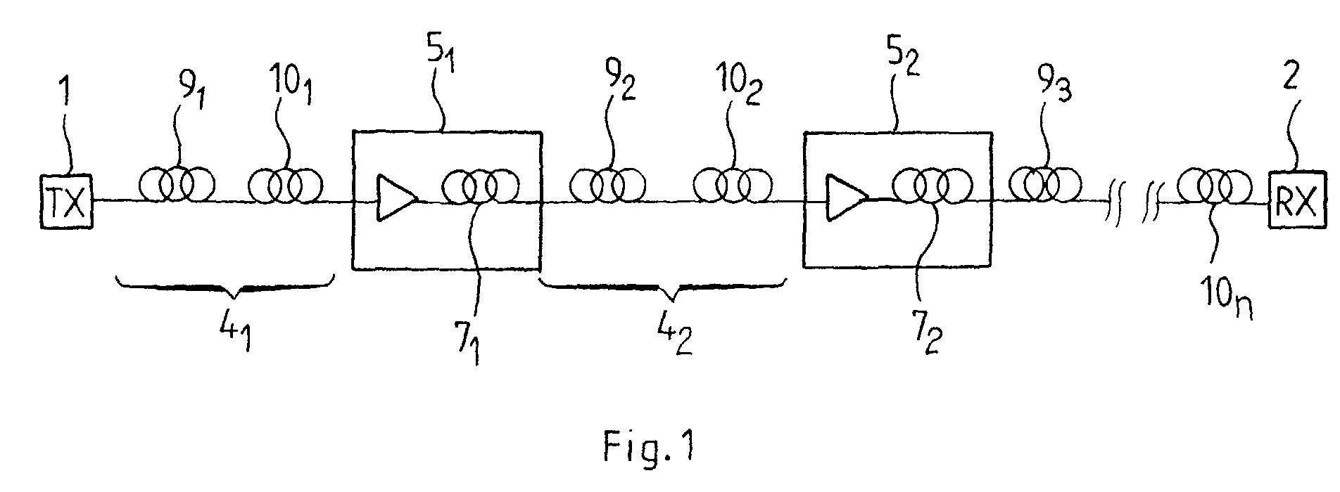
- Figure 1 shows a schematic representation of a transmission system according to the invention.
- a transmitter TX 1 and a receiver RX 2 These two elements are connected by a plurality of sections of line fiber 4 1 to 4 n .
- Line fiber is understood here to mean fiber extending along the transmission system, the length of which corresponds substantially to the length of the system. Between the sections are arranged repeaters 5 1 to 5 n-1 .
- a repeater typically includes an erbium-doped fiber amplifier; it is also possible to provide therein a section of dispersion compensation fiber 7 i . Filters and other elements are not shown in the figure without directly affecting the operation of the invention.
- At least one section of line fiber - preferably all the sections - is formed of a section 9 i of fiber according to the invention, which is connected to the output of the repeater, then of a section of fiber 10 i having a substantially constant chromatic dispersion.
- the operation of the transmission system in the figure is as follows.
- the transmitted signals are amplified in a repeater5 i-1 ; at the output of the repeater, the signals are first transmitted through the first part of the fiber 9 i , in which the chromatic dispersion is sufficiently high to limit the non-linear effects; the signals are then transmitted in the second part, in which the chromatic dispersion decreases rapidly.
- the signals then enter the second section 10 j of line fiber, where they are transmitted to the next repeater.
- the cumulative chromatic dispersion in a section of the line fiber is lower in the system of FIG. 1 than in a system according to the state of the art.
- a transmission system using NZ-DSF fiber with a chromatic dispersion of the order of 8 ps / (nm.km) at 1550 nm is considered for comparison.
- the cumulative chromatic dispersion is of the order of 800 ps / nm on a channel at 1550 nm; for a chromatic dispersion slope close to 0.058 ps / (nm 2 .km) at 1550 nm, the difference in cumulative chromatic dispersion between two channels separated by 30 nm, one centered at 1550 nm and the other at 1580 nm is of the order of 174 ps / nm.
- the fiber of the first section 9 j has a total length of 20 km; at its first end, it has a chromatic dispersion of 9 ps / (nm.km) and at its second end, a chromatic dispersion of 4 ps / (nm.km).
- the chromatic dispersion at 1550 nm decreases from 9 to 6.5 ps / (nm.km) over a length of 20 km at a rate of - 0.125 ps / (nm.km 2 );
- the second section of the fiber is an NZ-DSF fiber with a constant chromatic dispersion of 4 ps / (nm.km) at 1550 nm.
- the cumulative chromatic dispersion in the section is of the order of 475 ps / (nm.km) at 1550 nm.
- the average chromatic dispersion slope in the first part of the fiber 9 i is of the order of 0.042 ps / (nm 2 .km) at 1550 nm, while it is of the order of 0.024 in the fiber 10 i of the second section.
- the difference in cumulative chromatic dispersion between two channels separated by 30 nm, one centered at 1550 nm and the other at 1580 nm is of the order of 83 ps / (nm.km).
- the invention makes it possible to limit the length of the dispersion fiber of compensation necessary to compensate for the cumulative chromatic dispersion in line fiber and consequently reduce line losses.
- the invention makes it possible to reduce by one factor of about 1.7 the length of the dispersion compensating fiber to be used in the system and therefore reduces line losses by about 1.63 dB. This reduction can be obtained by a reduction in the fiber length in each of the repeaters with dispersion compensating fiber, but can also decrease the number of dispersion compensating fiber sections in the transmission system.
- dispersion fiber could be provided constant between the output of a repeater and the fiber of Figure 1; this has no effect on the functioning of the fiber of the invention and increases the chromatic dispersion cumulative as well as the number of welds between fibers. It is also clear that we can use a different type of dispersion compensation device than fiber dispersion compensation, and for example Bragg gratings or others; he is also possible that the dispersion compensating fiber is used as the fiber line. In all cases, the invention makes it possible to limit the chromatic dispersion accumulated to compensate.
- the fiber 10 i of the second section could as well be integrated into the fiber 9 i of the invention. This would further limit the losses caused by the welding of the two fiber sections.
- Bending losses are evaluated, in a manner known per se, in measuring the losses caused by the winding of the fiber.
- the limits on bending losses ensure that the fiber of the invention supports the cable setting.
- FIG. 2 shows a schematic representation of the chromatic dispersion, the chromatic dispersion slope and the mode radius as a function of the length of the fiber in a first embodiment of the invention.
- the chromatic dispersion in ps / (nm.km), the mode diameter W02 in ⁇ m and the chromatic dispersion slope in ps / (nm 2 .km) have been plotted on the ordinate.
- the chromatic dispersion varies continuously and regularly from a value of 9 ps / (nm.km) at the first end to a value of 6.5 ps / (nm.km) at the second end. This decrease corresponds to a rate of variation of the chromatic dispersion of -0.125 ps / (nm.km 2 ).
- the chromatic dispersion slope varies from 0.053 ps / (nm 2 .km) to 0.031 ps / (nm 2 .km).
- the mode diameter remains substantially constant over the entire length of the fiber, with a value close to 4 ⁇ m.
- the chromatic dispersion and the chromatic dispersion slope are on average 7.8 ps / (nm.km) and 0.042 ps / (nm 2 .km), respectively. More generally, the fiber could have a length of 10 to 35 km, and have a longitudinal variation rate of the chromatic dispersion between -1.4 and -0.05 ps / (nm.km 2 ). These values ensure that the variation in chromatic dispersion from one end to the other of the fiber is between 2.5 and 14 ps / (nm.km).
- the fiber of Figure 3 Around the buried trench, the fiber of Figure 3 has a ring, that is to say a part of index greater than the index of the sheath, hence the qualifier of rectangular profile with a buried trench and a ring.
- the following table gives the values of the indices and radii which make it possible to obtain the fiber of FIG. 2.
- r 1 the radius of the central part of the fiber
- r 2 the outside radius of the buried trench
- r 3 the outer radius of the ring.
- ⁇ n 1 , ⁇ n 2 and ⁇ n 3 the respective differences of the index of the rectangle, of the buried part and of the ring compared to the index of the sheath.
- the table below gives the different values of these parameters, at the two ends of the fiber in Figure 2.
- the table shows that the variation of the optical characteristics of the fiber can be obtained simply by varying the index of the buried trench .
- Such an index variation can be obtained during the constitution of a preform by continuously varying the concentration of dopants of the layers deposited during the deposition phase by MCVD or VAD.
- the variation of the profile in the fiber is described in the above as “continuous”; this "continuity" is in practice a function of the nature of the dopant concentration control systems implemented for the constitution of the preform. In practice, it turns out that the optical characteristics of the drawn fiber actually vary continuously along the fiber.
- Figure 4 shows a representation of other characteristics of propagation of the fiber of figure 2.
- FIG. 5 shows a representation of the efficiency of the 4-wave mixing as a function of the length L for two channels separated by a frequency difference equal to 50 GHz and a power of 20 dBm per channel.
- the calculation is carried out for a total section length of 100 km consisting of L km of the fiber in the example and (100-L) km of fiber with chromatic dispersion at + 4ps / nm / km and having an effective surface of 43 ⁇ m 2 .
- the horizontal line indicates the level of efficiency of the 4-wave mixture in 100 km of fiber characterized by a chromatic dispersion of + 7.5ps / nm / km and an effective surface of 60 ⁇ m 2 .
- Figure 5 shows that a 100 km section consisting of 20 km of fiber in the example and 80 km of fiber characterized by a constant chromatic dispersion of +4 ps / nm / km (and an effective surface of 43 ⁇ m 2 ) has a 4-wave mixing level comparable to that of a 100 km fiber with a constant chromatic dispersion of + 7.5 ps / nm / km and an effective surface of 60 ⁇ m 2 .
- the cumulative chromatic dispersion is 475 ps / nm. Knowing that the slope of the average chromatic dispersion is respectively 0.024 and 0.042 ps / nm 2 / km for the second butted fiber and the fiber of the invention, an average chromatic dispersion slope of 0.0276 ps / nm 2 / is obtained km on the 100 km of the section. The difference in cumulative chromatic dispersion between two channels separated by 30 nm, one centered at 1550 nm and the other at 1580 nm is therefore of the order of 83 ps / nm.
- the cumulative chromatic dispersion is equal to 750ps / nm at the end of the section and the difference in cumulative chromatic dispersion between two channels separated by 30 nm, one centered at 1550 nm and the other at 1580 nm is 174 ps / nm.
- the use of the fiber of FIG. 2 therefore makes it possible to significantly reduce the cumulative chromatic dispersion in the line fiber.
- the invention makes it possible to reduce by a factor of around 1.6 the length of the compensation fiber to be used in the system and allows reduce line losses by approximately 1.4 dB.
- Another benefit of using the fiber of the invention is the sharp reduction in the chromatic dispersion slope medium thanks to the use of fiber with low chromatic dispersion in the second part of the stretch.
- the fiber of the invention the fiber with low chromatic dispersion which is used in the transmission. This solution avoids welding to form the line fiber.
- Figure 6 is similar to Figure 2. It shows that the fiber has, in the vicinity of the first end, a first part in which the chromatic dispersion varies slowly. The fiber has, near its second end, a second part in which the chromatic dispersion is substantially constant. Between these two parts, the chromatic dispersion decreases with a greater longitudinal rate of change than in the first part. More specifically, it is still advantageous for the first part to have a length greater than or equal to 10 km, and a rate of longitudinal variation in the chromatic dispersion of between -0.6 and +0.1 ps / nm / km 2 . It is not essential for the invention that the chromatic dispersion be decreasing as in the example in the figure.
- the fiber In the vicinity of the second end, the fiber has a second part; this has a chromatic dispersion of less than 4 ps / (nm.km).
- the cumulative chromatic dispersion in the fiber is less than that of a the state of the art; as the signal strength is more limited in this section of the fiber, the non-linear effects are not penalizing.
- the chromatic dispersion in this second part is always greater than 3 ps / (nm.km); however, it is not essential that the dispersion chromatic is constant as in the example.
- the chromatic dispersion decreases, with a rate of variation typically between -14 and -0.5 ps / (nm.km 2 ). These limits are determined by imposing that the chromatic dispersion decreases by at least +2.5 ps / (nm.km) and at most by +14 ps / (nm.km) over a distance of 1 to 5 km between the two fiber parts considered above. With such values, the reduction in the chromatic dispersion between the two parts of the fiber ensures a reduction in the cumulative chromatic dispersion from at least 225 ps / nm to at most 1050 ps / nm when the length of the second part is 75 km.
- the chromatic dispersion and the chromatic dispersion slope are on average 4.15 ps / nm / km and 0.024 ps / nm 2 / km, respectively.
- This example advantageously corresponds to a manufacture of the preform by the process described in EP-A-0 737 873 or to a manufacture of the preform by VAD. It is also possible, in particular in the case of a fiber obtained by MCVD, to provide that the chromatic dispersion varies over a length of 10 to 35 km, with a rate of longitudinal variation of between -1.4 and -0.07 ps / (nm.km 2 ).
- Line (I) gives the values at the first end of the fiber
- line (II) the values at the end of the first part
- line (III) the values in the second part.
- the radii r1, r2 and r3 vary homothetically between the start and the end of a section. These radii decrease by a factor of approximately 1.035 between the beginning and the end of the section (I) (transition from the profile of index I to the profile of index II) and the start and the end of the section (II) (transition from index II profile to index III profile).
- Section (III) keeps the index III profile.
- Such variations in radii can be obtained for example by linearly varying the diameter of the refill in the sections of preforms corresponding to zones (I) and (II).
- the section (I) has a length of 19 km on fiber corresponding to a length of approximately 9 cm on the preform, while the section (II) has a length of 1 km on fiber corresponding to a length of about 0.4 cm on preform.
- Figure 7 is similar to Figure 4. It shows the variations longitudinal and local curvature losses, effective area and theoretical cut-off wavelength.
- Figure 8 is similar to Figure 5. It shows a representation of the efficiency of the 4-wave mixture as a function of the length L for two channels separated by a frequency difference equal to 50 GHz and a power of 20 dBm per channel . The calculation is carried out for a total section length of 100 km by varying the length L of the section (I) + (II). The horizontal line indicates the level of efficiency of the 4-wave mixture in 100 km of fiber characterized by a chromatic dispersion of + 7.5ps / nm / km and an effective surface of 43 ⁇ m 2 .
- FIG. 8 shows that the fiber of the example has a level of 4-wave mixing comparable to that of a fiber of 100 km characterized by a chromatic dispersion of +7.5 ps / nm / km and an effective surface of 43 ⁇ m 2 .
- the cumulative chromatic dispersion is 440 ps / nm.
- the difference in cumulative chromatic dispersion between two channels separated by 30 nm, one centered at 1550 nm and the other at 1580 nm is of the order of 72 ps / nm.
- the fibers are in one piece and come from the same preform. We can then achieve a longitudinal and continuous variation of the transmission characteristics by varying linearly the thicknesses of the layers deposited on preform by the CVD or VAD process - as in the example of the first embodiment where the index ⁇ n 2 decreases linearly from 0 to -1.9.10 -3 .
- the longitudinal variations in the transmission characteristics then depend on those of the index profile.
- this solution avoids making many fibers of different chromatic dispersion - therefore a difficulty technique - to approximate the profile of figure 2.
- this solution avoids losses by welding of all the spliced fibers. It takes almost a loss of approximately 0.1dB per weld for fibers having the same mode diameter.
- use for the first part of the fiber a spliced fiber has, in addition to the drawbacks mentioned above, the drawback not being able to decrease the chromatic dispersion over the first 20 (approximately) kilometers.
- the decrease in the chromatic dispersion in the first part reduces the dispersion cumulative chromaticity of nearly 50 ps / nm.
- the fiber of the invention can be manufactured by a person skilled in the art using known techniques, such as MCVD, OVD or other commonly used techniques used for the manufacture of optical fibers. It will be noted with respect to the processes from the state of the art that the fiber can be produced without variation of the spokes on along the fiber. This considerably simplifies the preparation process for the preform. It is enough to change during the deposit the concentration in the dopant filed to vary the indices. But it is not necessary to obtain a variation of the thickness of each layer deposited.
- the present invention is not limited to the examples and modes described and represented, but it is likely to be numerous variants accessible to those skilled in the art.
- the fiber of the invention can be used in systems other than those shown in Figure 1; we can also get a fiber according to the invention with a profile different from that of FIG. 3.
- the first mode as in the second it is possible to choose other values of chromatic dispersion than those proposed by way of example.
Landscapes
- Physics & Mathematics (AREA)
- Chemical & Material Sciences (AREA)
- Dispersion Chemistry (AREA)
- General Physics & Mathematics (AREA)
- Optics & Photonics (AREA)
- Electromagnetism (AREA)
- Engineering & Computer Science (AREA)
- Computer Networks & Wireless Communication (AREA)
- Signal Processing (AREA)
- Optical Communication System (AREA)
- Yarns And Mechanical Finishing Of Yarns Or Ropes (AREA)
Abstract
Description
- figure 1, un exemple de système de transmission utilisant une fibre selon l'invention;
- figure 2, une représentation schématique de la dispersion chromatique,de la pente de dispersion chromatique et du rayon de mode en fonction de la longueur de la fibre dans un mode de réalisation de l'invention;
- figure 3, un exemple de l'allure générale du profil d'une fibre selon l'invention;
- figure 4, une représentation des caractéristiques de propagation de la fibre de la figure 2;
- figure 5, un graphe montrant l'efficacité du mélange quatre ondes dans un système du genre de celui de la figure 1, avec une fibre du genre de celle de la figure 2;
- figures 6, 7 et 8, des représentations similaires à celles des figures 2, 4 et 5, pour un deuxième mode de réalisation d'une fibre selon l'invention.
- une longueur d'onde de coupure mesurée sur 2 m inférieure à 1550 nm;
- une longueur d'onde de coupure en câble inférieure à 1300 nm;
- une aire effective supérieure à 40 µm2, de préférence supérieure à 45 µm2;
- sensibilité aux micro-courbures inférieure à 1, ou de préférence inférieure ou égale à 0,5;
- un diamètre de mode supérieur à 4 µm;
- des pertes par courbure inférieures à 10-3 dB pour 100 tours à un rayon de 30 mm.
- des pertes par courbure inférieures à 20 dB/m pour une boucle de rayon 10 mm.
- une partie centrale avec un indice sensiblement constant supérieur ou égal à l'indice de la gaine;
- une partie annulaire d'indice inférieur ou égal à l'indice de la gaine ; l'ensemble constituant un profil d'indice dit "en rectangle avec une tranchée enterrée
| r1 (µm) | r2 (µm) | r3 (µm) | Δn1x1000 | Δn2x1000 | Δn3x1000 |
| 3,23 | 6,81 | 9,95 | 7,5 | 0 | 2,3 |
| 3,23 | 6,81 | 9,95 | 7,5 | -1,9 | 2,3 |
| Profil | r1 (µm) | r2 (µm) | r3 (µm) | Δn1x1000 | Δn2x1000 | Δn3x1000 |
| I | 3,32 | 6,22 | 8,9 | 8,6 | -3,65 | 3 |
| II | 3,21 | 6,01 | 8,6 | 8,6 | -3,65 | 3 |
| III | 3,1 | 5,8 | 8,3 | 8,6 | -3,65 | 3 |
Claims (17)
- Une fibre optique présentant à sa première extrémité une dispersion chromatique comprise entre +6 et +17 ps/(nm.km) et à sa deuxième extrémité une dispersion chromatique comprise entre +3 et +14 ps/(nm.km) la différence entre la dispersion chromatique à la première extrémité de la fibre et la dispersion chromatique à la deuxième extrémité de la fibre étant supérieure ou égale à 2,5 ps/(nm.km), la dispersion chromatique variant continûment le long de la fibre.
- La fibre selon la revendication 1 caractérisée en ce qu'elle présente au voisinage de sa première extrémité une première partie dans laquelle la dispersion chromatique est supérieure ou égale en moyenne à 6 ps/(nm.km).
- La fibre de la revendication 2, caractérisée en ce que la première partie présente une longueur supérieure ou égale à 10 km.
- La fibre de la revendication 2 ou 3, caractérisée en ce que le taux de variation longitudinale de la dispersion chromatique dans la première partie est compris entre -1,4 et +0,1 ps/(nm.km2).
- La fibre de l'une des revendications 1 à 4, caractérisée en ce que le taux de variation de dispersion chromatique le long de la fibre est sensiblement constant.
- La fibre de la revendication 5, caractérisée en ce que le taux présente une valeur comprise entre -1,4 et-0,05 ps/(nm.km2).
- La fibre de l'une des revendications 1 à 4, caractérisée en ce que la variation de dispersion chromatique s'effectue sensiblement complètement dans une partie de la fibre présentant une longueur inférieure à la longueur totale de la fibre.
- La fibre de la revendication 7, caractérisée en ce que la longueur de la partie de la fibre où la dispersion chromatique décroít est comprise entre 10 et 35 km.
- La fibre de la revendication 8, caractérisée en ce que le taux de variation longitudinale de la dispersion chromatique dans la partie de la fibre où la dispersion chromatique décroít est compris entre -1,4 et -0,07 ps/(nm.km2).
- La fibre de la revendication 7, caractérisée en ce que la longueur de la partie de la fibre où la dispersion chromatique décroít est comprise entre 1 et 5 km.
- La fibre de la revendication 10, caractérisée en ce que le taux de variation longitudinale de la dispersion chromatique dans la partie de la fibre où la dispersion chromatique décroít est compris entre -14 et -0,5 ps/(nm.km2).
- La fibre de l'une des revendications 1 à 4 et 7 à 11, caractérisée en ce qu'elle présente au voisinage de sa deuxième extrémité une deuxième partie dans laquelle la dispersion chromatique est inférieure ou égale à 14 ps/(nm.km).
- La fibre de la revendication 12, caractérisée en ce que la deuxième partie présente une longueur supérieure ou égale à 1 km.
- La fibre de l'une des revendications 1 à 13, caractérisée en ce qu'elle présente en tout point un profil d'indice en rectangle avec une tranchée déprimée et un anneau.
- La fibre de la revendication 14, caractérisée en ce que les rayons du rectangle, de la tranchée déprimée et de l'anneau sont identiques le long de la fibre.
- Un système de transmission, avec au moins un répéteur, une fibre selon l'une des revendications 1 à 15 recevant par sa première extrémité les signaux amplifiés dans le répéteur.
- Le système de la revendication 16, caractérisé par une fibre à dispersion sensiblement constante connectée à la deuxième extrémité de la dite fibre.
Applications Claiming Priority (2)
| Application Number | Priority Date | Filing Date | Title |
|---|---|---|---|
| FR0110849A FR2828742B1 (fr) | 2001-08-16 | 2001-08-16 | Fibre a changement continu de dispersion chromatique |
| FR0110849 | 2001-08-16 |
Publications (2)
| Publication Number | Publication Date |
|---|---|
| EP1291685A1 true EP1291685A1 (fr) | 2003-03-12 |
| EP1291685B1 EP1291685B1 (fr) | 2010-12-01 |
Family
ID=8866558
Family Applications (1)
| Application Number | Title | Priority Date | Filing Date |
|---|---|---|---|
| EP02291822A Expired - Lifetime EP1291685B1 (fr) | 2001-08-16 | 2002-07-18 | Fibre à changement continu de dispersion chromatique |
Country Status (6)
| Country | Link |
|---|---|
| US (1) | US6813426B2 (fr) |
| EP (1) | EP1291685B1 (fr) |
| CN (1) | CN1261810C (fr) |
| AT (1) | ATE490482T1 (fr) |
| DE (1) | DE60238466D1 (fr) |
| FR (1) | FR2828742B1 (fr) |
Families Citing this family (4)
| Publication number | Priority date | Publication date | Assignee | Title |
|---|---|---|---|---|
| FR2842676B1 (fr) * | 2002-07-18 | 2007-07-20 | Cit Alcatel | Procede de realisation et d'amelioration d'une ligne de transmission optique et modules de compensation associes |
| TW200601647A (en) * | 2004-06-03 | 2006-01-01 | Univ Nat Chiao Tung | Tunable optical fiber amplifier and laser device |
| FR2900739B1 (fr) * | 2006-05-03 | 2008-07-04 | Draka Comteq France | Fibre de compensation de la dispersion chromatique |
| WO2016034913A1 (fr) * | 2014-09-03 | 2016-03-10 | Draka Comteq Bv | Procédé de qualification de la largeur de bande modale effective d'une fibre multimode sur une large plage de longueurs d'onde à partir d'une mesure dmd d'une unique longueur d'onde et procédé pour sélectionner une fibre multimode à grande largeur de bande modale effective à partir d'un lot de fibres multimode |
Citations (6)
| Publication number | Priority date | Publication date | Assignee | Title |
|---|---|---|---|---|
| US5483612A (en) * | 1994-10-17 | 1996-01-09 | Corning Incorporated | Increased capacity optical waveguide |
| EP0724171A2 (fr) * | 1995-01-26 | 1996-07-31 | Corning Incorporated | Fibre optique avec une grande section effective |
| EP0789256A2 (fr) * | 1996-02-12 | 1997-08-13 | Lucent Technologies Inc. | Fibres optiques avec dispersion décroissante pour systèmes de transmission WDM à soliton |
| JPH11160744A (ja) * | 1997-12-01 | 1999-06-18 | Nippon Telegr & Teleph Corp <Ntt> | コヒーレント広帯域光源 |
| US5925163A (en) * | 1993-12-27 | 1999-07-20 | Corning, Inc. | Method of making an optical fiber with an axially decreasing group velocity dispersion |
| EP1113314A1 (fr) * | 1999-06-30 | 2001-07-04 | The Furukawa Electric Co., Ltd. | Fibre optique |
Family Cites Families (4)
| Publication number | Priority date | Publication date | Assignee | Title |
|---|---|---|---|---|
| US6321016B1 (en) * | 1998-06-19 | 2001-11-20 | Pirelli Cavi E Sistemi S.P.A. | Optical fiber having low non-linearity for WDM transmission |
| FR2788138B1 (fr) * | 1999-01-04 | 2001-03-30 | Cit Alcatel | Fibre optique a faible pente de dispersion chromatique |
| JP3567782B2 (ja) * | 1999-03-09 | 2004-09-22 | Kddi株式会社 | 分散補償光伝送路及びシステム |
| WO2001038911A1 (fr) * | 1999-11-22 | 2001-05-31 | Corning Incorporated | Fibre guide d'ondes a dispersion decalee a grande surface efficace |
-
2001
- 2001-08-16 FR FR0110849A patent/FR2828742B1/fr not_active Expired - Fee Related
-
2002
- 2002-07-18 DE DE60238466T patent/DE60238466D1/de not_active Expired - Lifetime
- 2002-07-18 AT AT02291822T patent/ATE490482T1/de not_active IP Right Cessation
- 2002-07-18 EP EP02291822A patent/EP1291685B1/fr not_active Expired - Lifetime
- 2002-08-01 US US10/208,779 patent/US6813426B2/en not_active Expired - Fee Related
- 2002-08-14 CN CN02127888.1A patent/CN1261810C/zh not_active Expired - Fee Related
Patent Citations (6)
| Publication number | Priority date | Publication date | Assignee | Title |
|---|---|---|---|---|
| US5925163A (en) * | 1993-12-27 | 1999-07-20 | Corning, Inc. | Method of making an optical fiber with an axially decreasing group velocity dispersion |
| US5483612A (en) * | 1994-10-17 | 1996-01-09 | Corning Incorporated | Increased capacity optical waveguide |
| EP0724171A2 (fr) * | 1995-01-26 | 1996-07-31 | Corning Incorporated | Fibre optique avec une grande section effective |
| EP0789256A2 (fr) * | 1996-02-12 | 1997-08-13 | Lucent Technologies Inc. | Fibres optiques avec dispersion décroissante pour systèmes de transmission WDM à soliton |
| JPH11160744A (ja) * | 1997-12-01 | 1999-06-18 | Nippon Telegr & Teleph Corp <Ntt> | コヒーレント広帯域光源 |
| EP1113314A1 (fr) * | 1999-06-30 | 2001-07-04 | The Furukawa Electric Co., Ltd. | Fibre optique |
Non-Patent Citations (4)
| Title |
|---|
| BOGATYREV V A ET AL: "A single-mode fiber with chromatic dispersion varying along the length", JOURNAL OF LIGHTWAVE TECHNOLOGY, IEEE. NEW YORK, US, vol. 9, no. 5, May 1991 (1991-05-01), pages 561 - 566, XP002173478, ISSN: 0733-8724 * |
| KOZUHITO TAJIMA: "COMPENSATION OF SOLITON BROADENING IN NONLINEAR OPTICAL FIBERS WITHLOSS", OPTICS LETTERS, OPTICAL SOCIETY OF AMERICA, WASHINGTON, US, vol. 12, no. 1, 1987, pages 54 - 56, XP000575387, ISSN: 0146-9592 * |
| NAKAJIMA K ET AL: "FOUR-WAVE MIXING SUPPRESSION EFFECT OF DISPERSION DISTRIBUTED FIBERS", JOURNAL OF LIGHTWAVE TECHNOLOGY, IEEE. NEW YORK, US, vol. 17, no. 10, October 1999 (1999-10-01), pages 1814 - 1822, XP001033240, ISSN: 0733-8724 * |
| PATENT ABSTRACTS OF JAPAN vol. 1999, no. 11 30 September 1999 (1999-09-30) * |
Also Published As
| Publication number | Publication date |
|---|---|
| EP1291685B1 (fr) | 2010-12-01 |
| US6813426B2 (en) | 2004-11-02 |
| CN1407358A (zh) | 2003-04-02 |
| ATE490482T1 (de) | 2010-12-15 |
| FR2828742B1 (fr) | 2004-01-16 |
| US20030044145A1 (en) | 2003-03-06 |
| CN1261810C (zh) | 2006-06-28 |
| FR2828742A1 (fr) | 2003-02-21 |
| DE60238466D1 (de) | 2011-01-13 |
Similar Documents
| Publication | Publication Date | Title |
|---|---|---|
| EP1067412A1 (fr) | Fibre optique à compensation de dispersion chromatique | |
| EP1030199B1 (fr) | Fibre de ligne pour systèmes de transmission à fibre optique à multiplexage en longueurs d'onde | |
| FR2900739A1 (fr) | Fibre de compensation de la dispersion chromatique | |
| FR2941540A1 (fr) | Fibre optique monomode presentant une surface effective elargie | |
| EP1217399B1 (fr) | Fibre pour la compensation de dispersion chromatique d'une fibre NZ-DSF à dispersion chromatique positive | |
| AU1173299A (en) | Dispersion-shifted optical fiber | |
| EP1004905B1 (fr) | Fibre de compensation de dispersion pour système de transmission à fibre optique à multiplexage en longueur d'onde employant une fibre de ligne à dispersion décalée | |
| EP0987568A1 (fr) | Fibre optique monomode à dispersion décalée optimisée pour les hauts débits | |
| EP1764634A1 (fr) | Fibre de compensation de la dispersion chromatique et de la pente de dispersion cumulées | |
| EP0992817A1 (fr) | Fibre optique monomode à dispersion décalée à grande aire effective | |
| FR2799006A1 (fr) | Fibre optique pour la compensation en ligne de la dispersion chromatique d'une fibre optique a dispersion chromatique positive | |
| EP1202087B1 (fr) | Fibre pour la compensation de la dispersion chromatique en bande S d'une fibre monomode | |
| EP1128196A1 (fr) | Fibre optique monomode en cable pour reseaux de transmission à fibre optique à multiplexage en longueurs d'onde | |
| EP1018656B1 (fr) | Fibre optique à faible pente de dispersion chromatique | |
| EP1291685B1 (fr) | Fibre à changement continu de dispersion chromatique | |
| EP1030474A1 (fr) | Système, ligne et procédé de transmission à fibre optique | |
| EP1202088A1 (fr) | Fibre optique pour la compensation en ligne de la dispersion chromatique d'une fibre optique à dispersion chromatique positive | |
| EP1213595A2 (fr) | Compensation de la dispersion chromatique dans un système de transmission à fibre optique, et fibre de compensation | |
| EP1327898A1 (fr) | Fibre optique à profil d'indice complexe en forme d'anneaux | |
| EP1361685A1 (fr) | Fibre de compensation de la dispersion chromatique cumulée dans une fibre à dispersion chromatique négative | |
| EP1288682B1 (fr) | Fibre optique pour système de transmission à multiplexage en longueurs d'onde | |
| EP1018812B1 (fr) | Système de transmission à fibre optique à multiplexage en longueur d'onde avec compensation de la dispersion chromatique | |
| EP1168685A1 (fr) | Compensation de dispersion chromatique dans un système de transmission optique large bande |
Legal Events
| Date | Code | Title | Description |
|---|---|---|---|
| PUAI | Public reference made under article 153(3) epc to a published international application that has entered the european phase |
Free format text: ORIGINAL CODE: 0009012 |
|
| AK | Designated contracting states |
Kind code of ref document: A1 Designated state(s): AT BE BG CH CY CZ DE DK EE ES FI FR GB GR IE IT LI LU MC NL PT SE SK TR |
|
| AX | Request for extension of the european patent |
Extension state: AL LT LV MK RO SI |
|
| 17P | Request for examination filed |
Effective date: 20030912 |
|
| AKX | Designation fees paid |
Designated state(s): AT BE BG CH CY CZ DE DK EE ES FI FR GB GR IE IT LI LU MC NL PT SE SK TR |
|
| 17Q | First examination report despatched |
Effective date: 20031208 |
|
| RAP1 | Party data changed (applicant data changed or rights of an application transferred) |
Owner name: DRAKA COMTEQ B.V. |
|
| 17Q | First examination report despatched |
Effective date: 20031208 |
|
| RAP1 | Party data changed (applicant data changed or rights of an application transferred) |
Owner name: DRAKA COMTEQ B.V. |
|
| RAP1 | Party data changed (applicant data changed or rights of an application transferred) |
Owner name: DRAKA COMTEQ B.V. |
|
| RIC1 | Information provided on ipc code assigned before grant |
Ipc: G02B 6/02 20060101AFI20100319BHEP |
|
| GRAP | Despatch of communication of intention to grant a patent |
Free format text: ORIGINAL CODE: EPIDOSNIGR1 |
|
| GRAS | Grant fee paid |
Free format text: ORIGINAL CODE: EPIDOSNIGR3 |
|
| GRAA | (expected) grant |
Free format text: ORIGINAL CODE: 0009210 |
|
| AK | Designated contracting states |
Kind code of ref document: B1 Designated state(s): AT BE BG CH CY CZ DE DK EE ES FI FR GB GR IE IT LI LU MC NL PT SE SK TR |
|
| REG | Reference to a national code |
Ref country code: GB Ref legal event code: FG4D Free format text: NOT ENGLISH |
|
| REG | Reference to a national code |
Ref country code: CH Ref legal event code: EP |
|
| REG | Reference to a national code |
Ref country code: IE Ref legal event code: FG4D |
|
| REF | Corresponds to: |
Ref document number: 60238466 Country of ref document: DE Date of ref document: 20110113 Kind code of ref document: P |
|
| REG | Reference to a national code |
Ref country code: NL Ref legal event code: VDEP Effective date: 20101201 |
|
| PG25 | Lapsed in a contracting state [announced via postgrant information from national office to epo] |
Ref country code: CY Free format text: LAPSE BECAUSE OF FAILURE TO SUBMIT A TRANSLATION OF THE DESCRIPTION OR TO PAY THE FEE WITHIN THE PRESCRIBED TIME-LIMIT Effective date: 20101201 Ref country code: SE Free format text: LAPSE BECAUSE OF FAILURE TO SUBMIT A TRANSLATION OF THE DESCRIPTION OR TO PAY THE FEE WITHIN THE PRESCRIBED TIME-LIMIT Effective date: 20101201 Ref country code: AT Free format text: LAPSE BECAUSE OF FAILURE TO SUBMIT A TRANSLATION OF THE DESCRIPTION OR TO PAY THE FEE WITHIN THE PRESCRIBED TIME-LIMIT Effective date: 20101201 Ref country code: BG Free format text: LAPSE BECAUSE OF FAILURE TO SUBMIT A TRANSLATION OF THE DESCRIPTION OR TO PAY THE FEE WITHIN THE PRESCRIBED TIME-LIMIT Effective date: 20110301 Ref country code: NL Free format text: LAPSE BECAUSE OF FAILURE TO SUBMIT A TRANSLATION OF THE DESCRIPTION OR TO PAY THE FEE WITHIN THE PRESCRIBED TIME-LIMIT Effective date: 20101201 Ref country code: FI Free format text: LAPSE BECAUSE OF FAILURE TO SUBMIT A TRANSLATION OF THE DESCRIPTION OR TO PAY THE FEE WITHIN THE PRESCRIBED TIME-LIMIT Effective date: 20101201 |
|
| REG | Reference to a national code |
Ref country code: IE Ref legal event code: FD4D |
|
| PG25 | Lapsed in a contracting state [announced via postgrant information from national office to epo] |
Ref country code: GR Free format text: LAPSE BECAUSE OF FAILURE TO SUBMIT A TRANSLATION OF THE DESCRIPTION OR TO PAY THE FEE WITHIN THE PRESCRIBED TIME-LIMIT Effective date: 20110302 |
|
| PG25 | Lapsed in a contracting state [announced via postgrant information from national office to epo] |
Ref country code: EE Free format text: LAPSE BECAUSE OF FAILURE TO SUBMIT A TRANSLATION OF THE DESCRIPTION OR TO PAY THE FEE WITHIN THE PRESCRIBED TIME-LIMIT Effective date: 20101201 Ref country code: CZ Free format text: LAPSE BECAUSE OF FAILURE TO SUBMIT A TRANSLATION OF THE DESCRIPTION OR TO PAY THE FEE WITHIN THE PRESCRIBED TIME-LIMIT Effective date: 20101201 Ref country code: ES Free format text: LAPSE BECAUSE OF FAILURE TO SUBMIT A TRANSLATION OF THE DESCRIPTION OR TO PAY THE FEE WITHIN THE PRESCRIBED TIME-LIMIT Effective date: 20110312 Ref country code: PT Free format text: LAPSE BECAUSE OF FAILURE TO SUBMIT A TRANSLATION OF THE DESCRIPTION OR TO PAY THE FEE WITHIN THE PRESCRIBED TIME-LIMIT Effective date: 20110401 Ref country code: IE Free format text: LAPSE BECAUSE OF FAILURE TO SUBMIT A TRANSLATION OF THE DESCRIPTION OR TO PAY THE FEE WITHIN THE PRESCRIBED TIME-LIMIT Effective date: 20101201 |
|
| PG25 | Lapsed in a contracting state [announced via postgrant information from national office to epo] |
Ref country code: SK Free format text: LAPSE BECAUSE OF FAILURE TO SUBMIT A TRANSLATION OF THE DESCRIPTION OR TO PAY THE FEE WITHIN THE PRESCRIBED TIME-LIMIT Effective date: 20101201 |
|
| PLBE | No opposition filed within time limit |
Free format text: ORIGINAL CODE: 0009261 |
|
| STAA | Information on the status of an ep patent application or granted ep patent |
Free format text: STATUS: NO OPPOSITION FILED WITHIN TIME LIMIT |
|
| PG25 | Lapsed in a contracting state [announced via postgrant information from national office to epo] |
Ref country code: DK Free format text: LAPSE BECAUSE OF FAILURE TO SUBMIT A TRANSLATION OF THE DESCRIPTION OR TO PAY THE FEE WITHIN THE PRESCRIBED TIME-LIMIT Effective date: 20101201 |
|
| 26N | No opposition filed |
Effective date: 20110902 |
|
| REG | Reference to a national code |
Ref country code: DE Ref legal event code: R097 Ref document number: 60238466 Country of ref document: DE Effective date: 20110902 |
|
| PG25 | Lapsed in a contracting state [announced via postgrant information from national office to epo] |
Ref country code: IT Free format text: LAPSE BECAUSE OF FAILURE TO SUBMIT A TRANSLATION OF THE DESCRIPTION OR TO PAY THE FEE WITHIN THE PRESCRIBED TIME-LIMIT Effective date: 20101201 |
|
| BERE | Be: lapsed |
Owner name: DRAKA COMTEQ B.V. Effective date: 20110731 |
|
| PG25 | Lapsed in a contracting state [announced via postgrant information from national office to epo] |
Ref country code: MC Free format text: LAPSE BECAUSE OF NON-PAYMENT OF DUE FEES Effective date: 20110731 |
|
| REG | Reference to a national code |
Ref country code: CH Ref legal event code: PL |
|
| PG25 | Lapsed in a contracting state [announced via postgrant information from national office to epo] |
Ref country code: BE Free format text: LAPSE BECAUSE OF NON-PAYMENT OF DUE FEES Effective date: 20110731 Ref country code: CH Free format text: LAPSE BECAUSE OF NON-PAYMENT OF DUE FEES Effective date: 20110731 Ref country code: LI Free format text: LAPSE BECAUSE OF NON-PAYMENT OF DUE FEES Effective date: 20110731 |
|
| PG25 | Lapsed in a contracting state [announced via postgrant information from national office to epo] |
Ref country code: LU Free format text: LAPSE BECAUSE OF NON-PAYMENT OF DUE FEES Effective date: 20110718 |
|
| PG25 | Lapsed in a contracting state [announced via postgrant information from national office to epo] |
Ref country code: TR Free format text: LAPSE BECAUSE OF FAILURE TO SUBMIT A TRANSLATION OF THE DESCRIPTION OR TO PAY THE FEE WITHIN THE PRESCRIBED TIME-LIMIT Effective date: 20101201 |
|
| PGFP | Annual fee paid to national office [announced via postgrant information from national office to epo] |
Ref country code: DE Payment date: 20140729 Year of fee payment: 13 |
|
| PGFP | Annual fee paid to national office [announced via postgrant information from national office to epo] |
Ref country code: FR Payment date: 20140717 Year of fee payment: 13 Ref country code: GB Payment date: 20140729 Year of fee payment: 13 |
|
| REG | Reference to a national code |
Ref country code: DE Ref legal event code: R119 Ref document number: 60238466 Country of ref document: DE |
|
| GBPC | Gb: european patent ceased through non-payment of renewal fee |
Effective date: 20150718 |
|
| PG25 | Lapsed in a contracting state [announced via postgrant information from national office to epo] |
Ref country code: DE Free format text: LAPSE BECAUSE OF NON-PAYMENT OF DUE FEES Effective date: 20160202 Ref country code: GB Free format text: LAPSE BECAUSE OF NON-PAYMENT OF DUE FEES Effective date: 20150718 |
|
| REG | Reference to a national code |
Ref country code: FR Ref legal event code: ST Effective date: 20160331 |
|
| PG25 | Lapsed in a contracting state [announced via postgrant information from national office to epo] |
Ref country code: FR Free format text: LAPSE BECAUSE OF NON-PAYMENT OF DUE FEES Effective date: 20150731 |