EP1291482A1 - Hinge - Google Patents
Hinge Download PDFInfo
- Publication number
- EP1291482A1 EP1291482A1 EP02256242A EP02256242A EP1291482A1 EP 1291482 A1 EP1291482 A1 EP 1291482A1 EP 02256242 A EP02256242 A EP 02256242A EP 02256242 A EP02256242 A EP 02256242A EP 1291482 A1 EP1291482 A1 EP 1291482A1
- Authority
- EP
- European Patent Office
- Prior art keywords
- hinge
- panel
- supporting bracket
- angle
- opened
- Prior art date
- Legal status (The legal status is an assumption and is not a legal conclusion. Google has not performed a legal analysis and makes no representation as to the accuracy of the status listed.)
- Granted
Links
Images


Classifications
-
- E—FIXED CONSTRUCTIONS
- E05—LOCKS; KEYS; WINDOW OR DOOR FITTINGS; SAFES
- E05D—HINGES OR SUSPENSION DEVICES FOR DOORS, WINDOWS OR WINGS
- E05D11/00—Additional features or accessories of hinges
- E05D11/06—Devices for limiting the opening movement of hinges
-
- G—PHYSICS
- G06—COMPUTING OR CALCULATING; COUNTING
- G06F—ELECTRIC DIGITAL DATA PROCESSING
- G06F1/00—Details not covered by groups G06F3/00 - G06F13/00 and G06F21/00
- G06F1/16—Constructional details or arrangements
- G06F1/1613—Constructional details or arrangements for portable computers
- G06F1/1633—Constructional details or arrangements of portable computers not specific to the type of enclosures covered by groups G06F1/1615 - G06F1/1626
- G06F1/1675—Miscellaneous details related to the relative movement between the different enclosures or enclosure parts
- G06F1/1681—Details related solely to hinges
-
- G—PHYSICS
- G06—COMPUTING OR CALCULATING; COUNTING
- G06F—ELECTRIC DIGITAL DATA PROCESSING
- G06F1/00—Details not covered by groups G06F3/00 - G06F13/00 and G06F21/00
- G06F1/16—Constructional details or arrangements
- G06F1/1613—Constructional details or arrangements for portable computers
- G06F1/1615—Constructional details or arrangements for portable computers with several enclosures having relative motions, each enclosure supporting at least one I/O or computing function
- G06F1/1616—Constructional details or arrangements for portable computers with several enclosures having relative motions, each enclosure supporting at least one I/O or computing function with folding flat displays, e.g. laptop computers or notebooks having a clamshell configuration, with body parts pivoting to an open position around an axis parallel to the plane they define in closed position
-
- G—PHYSICS
- G06—COMPUTING OR CALCULATING; COUNTING
- G06F—ELECTRIC DIGITAL DATA PROCESSING
- G06F1/00—Details not covered by groups G06F3/00 - G06F13/00 and G06F21/00
- G06F1/16—Constructional details or arrangements
- G06F1/1613—Constructional details or arrangements for portable computers
- G06F1/1633—Constructional details or arrangements of portable computers not specific to the type of enclosures covered by groups G06F1/1615 - G06F1/1626
- G06F1/1675—Miscellaneous details related to the relative movement between the different enclosures or enclosure parts
- G06F1/1679—Miscellaneous details related to the relative movement between the different enclosures or enclosure parts for locking or maintaining the movable parts of the enclosure in a fixed position, e.g. latching mechanism at the edge of the display in a laptop or for the screen protective cover of a PDA
-
- E—FIXED CONSTRUCTIONS
- E05—LOCKS; KEYS; WINDOW OR DOOR FITTINGS; SAFES
- E05D—HINGES OR SUSPENSION DEVICES FOR DOORS, WINDOWS OR WINGS
- E05D11/00—Additional features or accessories of hinges
- E05D11/08—Friction devices between relatively-movable hinge parts
- E05D11/087—Friction devices between relatively-movable hinge parts with substantially axial friction, e.g. friction disks
-
- E—FIXED CONSTRUCTIONS
- E05—LOCKS; KEYS; WINDOW OR DOOR FITTINGS; SAFES
- E05F—DEVICES FOR MOVING WINGS INTO OPEN OR CLOSED POSITION; CHECKS FOR WINGS; WING FITTINGS NOT OTHERWISE PROVIDED FOR, CONCERNED WITH THE FUNCTIONING OF THE WING
- E05F1/00—Closers or openers for wings, not otherwise provided for in this subclass
- E05F1/08—Closers or openers for wings, not otherwise provided for in this subclass spring-actuated, e.g. for horizontally sliding wings
- E05F1/10—Closers or openers for wings, not otherwise provided for in this subclass spring-actuated, e.g. for horizontally sliding wings for swinging wings, e.g. counterbalance
- E05F1/12—Mechanisms in the shape of hinges or pivots, operated by springs
- E05F1/1207—Mechanisms in the shape of hinges or pivots, operated by springs with a coil spring parallel with the pivot axis
- E05F1/1215—Mechanisms in the shape of hinges or pivots, operated by springs with a coil spring parallel with the pivot axis with a canted-coil torsion spring
-
- E—FIXED CONSTRUCTIONS
- E05—LOCKS; KEYS; WINDOW OR DOOR FITTINGS; SAFES
- E05Y—INDEXING SCHEME ASSOCIATED WITH SUBCLASSES E05D AND E05F, RELATING TO CONSTRUCTION ELEMENTS, ELECTRIC CONTROL, POWER SUPPLY, POWER SIGNAL OR TRANSMISSION, USER INTERFACES, MOUNTING OR COUPLING, DETAILS, ACCESSORIES, AUXILIARY OPERATIONS NOT OTHERWISE PROVIDED FOR, APPLICATION THEREOF
- E05Y2999/00—Subject-matter not otherwise provided for in this subclass
Definitions
- the present invention relates to a hinge comprising first and second means for connecting the hinge to first and second structures, a shaft fixed to said first means and about which the second means can rotate and brake means for holding the first and second means for enabling the first and second means to be set in position relative to each other.
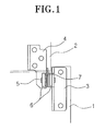
- FIG. 1 shows an example of a conventional hinge apparatus employed in a laptop computer.
- the hinge apparatus includes a fixing bracket 3 disposed on a body 1, a supporting bracket 4 fixed to a panel 2 that is opened and closed with respect to the body 1, a hinge shaft 5 connected to the fixing bracket 3 and the supporting bracket 4, a plurality of washers 6 disposed on the hinge shaft 5 and a plate spring 7.
- the supporting bracket 4 is connected between the washers 6, while the plate spring 7 is connected between the supporting shaft 4 and the washers 6. Accordingly, due to the elastic force of the plate spring 7, a frictional force is generated between the supporting shaft 4 and the washers 6. Due to the frictional force, the panel 2 is prevented from pivoting freely with respect to the body 1 when the appliance is open or closed. When the panel 2 is opened with respect to the body 1 by a predetermined angle, the panel 2 is fixed in its position by the frictional force. More specifically, a user may adjust the angle of the panel 2 with respect to the body 1 moving the panel 2 up or down manually.
- the above-described configuration is one of typical examples of the hinge apparatus, which needs an improvement in terms of handling. That is, even when a locking device, for holding the appliance closed, is released, the panel 2 remains tightly contacted with the body 1 and it is hard for the user to open the panel 2 manually.
- a hinge according to the present invention is characterised by means arranged such that the brake means becomes operative at a predetermined angle between the first and second means.
- a hinge according to the present invention comprises resilient means for biasing the hinge, when closed, towards an open position. More preferably, the resilient means comprises coil spring and the shaft extends axially through the spring. Still more preferably, a hinge according to the present invention comprises means for removing said bias substantially at said predetermined angle which may be a slot in the second means receiving an end of the spring.
- the brake means is mounted for rotation with the second means and comprises a projection and the means arranged such that the brake means becomes operative at a predetermined angle comprises a member fixed relative to the shaft and having a slot or cut-out for receiving said projection when the hinge is opened less than said predetermined angle, said projection bearing against said member to provide braking when the hinge is opened by said predetermined angle or a greater angle.
- a hinge according to the present invention is employed to connect a panel 11 to a body 10 of an appliance so that the panel 11 can be opened and closed with respect to the body 10.
- the hinge apparatus includes a fixing bracket 13 fixed onto the body 10, a supporting bracket 15 fixed to the panel 11, a hinge shaft 17, an automatic pivot unit 20, a manual pivot unit 30, and a fixing pin 40.
- a laptop computer will be used herein as an example of appliance in which a hinge according to the present invention, and accordingly, the body 10 is the laptop computer body, and the panel 11 is an LCD panel of the laptop computer.
- a general locking device is disposed between the body 10 and the panel 11. Accordingly, when a user desires to open the panel 11 with respect to the body 10, he/she may open it after releasing the locking device.
- the fixing bracket 13 is fixed onto the body 10 by screws (not shown).
- the fixing bracket 13 has a fixing hole 13a through which the hinge shaft 17 is fixed, and a supporting hole 13b to which one end of a coil spring 21, which will be described later, is fixed.
- the fixing hole 13a is non-circular.
- the supporting bracket 15 is fixed to the panel 11 by screws (not shown).
- the supporting bracket 15 faces the fixing bracket 13 at a predetermined distance.
- the supporting bracket 15 has a shaft hole 15a through which the hinge shaft 17 extends, and a guide hole 15b in which the other end of the coil spring 21 is received.
- the shaft hole 15a may be circular or non-circular and is larger than an outer circumference of the hinge shaft 17 to that the hinge shaft 17 can move freely therein. With the hinge shaft 17 extending through the shaft hole 15a, the supporting bracket 15 can be rotated relative to the hinge shaft 17.
- the hinge shaft 17 includes a body 17a, having a circular cross-section in its middle, non-circular cross-section fixing portions 17b extending from both ends of the body 17a, and a supporting portion 17c extending between one of the fixing portion 17b and the body 17a.
- the body 17a is connected to the coil spring 21.
- the fixing portion 17b is inserted into the fixing hole 13a and the shaft hole 15a.
- the free end of the fixing portion 17b, inserted through the shaft hole 15a has a circumferential groove 17d for receiving the circlip 40.
- the other end 17b is inserted into the fixing hole 13a of the fixing bracket 13 and then completely fixed by being caulked by a caulking device. Alternatively, this end of the fixing portion 17b may also be fastened by a circlip 40.
- the automatic pivot unit 20 is employed so that the panel 11 can open with respect to the body 10 automatically by a predetermined angle when the locking device is released.
- the automatic pivot unit 20 includes the coil spring 21, disposed on the hinge shaft 17, which elastically biases the panel 11 towards an open position with respect to the body 10.
- the guide hole 15b formed in the supporting bracket 15 is also part of the automatic pivot unit 20.
- one end of the coil spring 21 is received in the supporting hole 13b of the fixing bracket 13, while the other end is received in the guide hole 15b of the supporting bracket 15.
- the supporting bracket 15 is pressed in a direction as indicated by an arrow A as shown in Figure 4A.
- the direction as shown indicates the opening of the panel 11 with respect to the body 10.
- the torsion of the coil spring 21 is set at an appropriate level so that the panel 11 is automatically opened with respect to the body 10 by an angle of approximately 45°.
- the guide hole 15b is formed so as to have an appropriate length to correspond to the automatic opening angle of the panel 11.
- the manual pivot unit 30 restricts the angle of automatic rotation of the supporting bracket 15 by the automatic pivot unit 20.
- the manual pivot unit 30 also provides a frictional force between the supporting bracket 15 and the hinge shaft 17 to fix the supporting bracket 15 in a fixed position.
- the supporting bracket 15 is further opened by an external force from the automatic opening angle.
- the manual pivot unit 30 has a plate spring 31 fixed on the supporting bracket 15, and a friction plate 33 fixed on the hinge shaft 17 in tight contact with the plate spring 31.
- the plate spring 31 has a shaft hole 31a through which the hinge shaft 17 is passed, a pair of projections 31b, 31c protruding from one side of the plate spring 31, and a coupling portion 31d bent from a portion of an outline of the plate spring 31 opposite to the projections 31b, 31c.
- the plate spring 31 is fixed onto the supporting bracket 15 and rotated together with the supporting bracket 15.
- the shaft hole 31a has a circular shape.
- the projections 31b, 31c protrude from the one side of the plate spring 31.
- the projections 31b, 31c are also positioned such that their respective distances from the projections 31b, 31c to the shaft hole 31a are different.
- a coupling portion 31d is positioned to be fixed in a coupling hole 15c that is formed in the supporting bracket 15. Accordingly, the plate spring 31 is fixed onto the supporting bracket 15 and rotated together with the supporting bracket 15.
- the friction plate 33 is formed in tight contact with one surface of the plate spring 31.
- the friction plate 33 has a coupling hole 33a corresponding to a section of the fixing portion 17b so as to be connected to, and rotated together with the fixing portion 17b of the hinge shaft 17.
- the frictional plate 33 also has guide holes 33b, 33c corresponding to the projections 31b, 31c of the plate spring 31. Each of the guide holes 33b, 33c receives one of the projections 31b, 31c to guide movement of the projections 31b, 31c.
- the guide holes 33b, 33c are formed at different distances with respect to the coupling hole 33a.
- the supporting bracket 15, the plate spring 31 and the frictional plate 33 are connected to come into tight contact with the supporting portion 17c of the hinge shaft 17 sequentially. Separation from the hinge shaft 17 is prevented by the fixing pin 40.
- the pivoting angle restricting device includes a locking portion 33e protruding from an outline of the frictional plate 33, and a locking projection 15e bent from an outline of the supporting bracket 15 to be locked with the locking portion 33e during rotation.
- the locking portion 33e is formed in a position that restricts the pivoting angle of the supporting bracket 15 at a predetermined degree of, for example, 210°.
- the projections 31b, 31c of the plate spring 31 are inserted into the guide holes 33b, 33c of the friction plate 33.
- One end of the coil spring 21 is received at one end of the guide hole 15b. Accordingly, the supporting bracket 15 is resiliently biased in the direction A (as shown in Figure 4A) by the torsion of the coil spring 21.
- the supporting bracket 15 is automatically pivoted by approximately 45°, for example, by the coil spring 21. Since the lengths of the guide holes 33b, 33c correspond to an angle of 45°, the projections 31b, 31c are guided along the guide holes 33b, 33c through 45° without being interfered by frictional force or resistance.
- the supporting bracket 15 is automatically pivoted (opened) by approximately 45° together with the panel 11, the projections 31b, 31c are moved to the other ends of the guide holes 33b, 33c.
- the free rotation of the supporting bracket 15 is restricted.
- the hinge shaft 17 and the frictional plate 33 are in fixed positions with respect to the body 10.
- the supporting bracket 15 and the plate spring 31 are pivoted in the A direction (as shown in Figure 4A) together with the panel 11.
- the panel 11 is moved to the state as shown in Figures 6A and 6B when the panel 11 is forcibly pivoted in the A direction as shown in Figure 5 by approximately 180°. Movement by a user in addition to the free rotation angle of 45° allows for the panel 11 to be positioned in the state as shown in Figures 6A and 6B. Accordingly, the projections 31b, 31c of the plate spring 31 escape from the guide holes 33b, 33c and are positioned in contact with the one surface of the friction plate 33. By the contact between the projections 31b, 31c and the friction plate 33, a frictional force is generated between the friction plate 33 and the plate spring 31. The friction force has an indirect influence on the hinge shaft 17 and the supporting bracket 15. Accordingly, when the panel 11 is opened more than 45°, the opening is enabled by an external force that overcomes the frictional force. When the pivoting is stopped, the panel 11 is fixed in position by the frictional force.
- Figure 7 shows the panel 11 being rotated by approximately 210°.
- the locking projection 15e is locked with the locking portion 33e, thereby restricting the supporting bracket 15 from further rotation.
- the panel end of the coil spring 21 is freely guided along the guide hole 15b, and the coil spring 21 is kept uncompression.
- the hinge apparatus provides a first operation, which is automatic, and a second operation, which is manual.
- a first operation which is automatic
- a second operation which is manual.
- the locking device e.g., like pressing a button
- the panel 11 is automatically opened by a predetermined angle.
- a body of an appliance becomes easy to use.
- a user is allowed to adjustably open the panel 11 within an angle ranging from, e.g. about 45° to 210°.
- the hinge apparatus enables pivoting movement of the supporting bracket 15 with respect to the fixing bracket 13 in a two operation manner. More specifically, since opening in the first operation is performed automatically, while the opening in the second operation is performed manually by the user, the appliance becomes easier to use.
Landscapes
- Engineering & Computer Science (AREA)
- Computer Hardware Design (AREA)
- Theoretical Computer Science (AREA)
- Physics & Mathematics (AREA)
- Human Computer Interaction (AREA)
- General Engineering & Computer Science (AREA)
- General Physics & Mathematics (AREA)
- Mathematical Physics (AREA)
- Mechanical Engineering (AREA)
- Pivots And Pivotal Connections (AREA)
Abstract
Description
- The present invention relates to a hinge comprising first and second means for connecting the hinge to first and second structures, a shaft fixed to said first means and about which the second means can rotate and brake means for holding the first and second means for enabling the first and second means to be set in position relative to each other.
- Recently, there has been a great improvement in and marketing of folding electronic appliances such as camcorders and laptop computers in which an LCD panel is hinged to the appliance's body.
- Figure 1 shows an example of a conventional hinge apparatus employed in a laptop computer. As shown in Figure 1, the hinge apparatus includes a
fixing bracket 3 disposed on abody 1, a supportingbracket 4 fixed to apanel 2 that is opened and closed with respect to thebody 1, ahinge shaft 5 connected to thefixing bracket 3 and the supportingbracket 4, a plurality ofwashers 6 disposed on thehinge shaft 5 and aplate spring 7. - In the above-described configuration, the supporting
bracket 4 is connected between thewashers 6, while theplate spring 7 is connected between the supportingshaft 4 and thewashers 6. Accordingly, due to the elastic force of theplate spring 7, a frictional force is generated between the supportingshaft 4 and thewashers 6. Due to the frictional force, thepanel 2 is prevented from pivoting freely with respect to thebody 1 when the appliance is open or closed. When thepanel 2 is opened with respect to thebody 1 by a predetermined angle, thepanel 2 is fixed in its position by the frictional force. More specifically, a user may adjust the angle of thepanel 2 with respect to thebody 1 moving thepanel 2 up or down manually. - The above-described configuration is one of typical examples of the hinge apparatus, which needs an improvement in terms of handling. That is, even when a locking device, for holding the appliance closed, is released, the
panel 2 remains tightly contacted with thebody 1 and it is hard for the user to open thepanel 2 manually. - A hinge according to the present invention is characterised by means arranged such that the brake means becomes operative at a predetermined angle between the first and second means.
- Preferably, a hinge according to the present invention comprises resilient means for biasing the hinge, when closed, towards an open position. More preferably, the resilient means comprises coil spring and the shaft extends axially through the spring. Still more preferably, a hinge according to the present invention comprises means for removing said bias substantially at said predetermined angle which may be a slot in the second means receiving an end of the spring.
- Preferably, the brake means is mounted for rotation with the second means and comprises a projection and the means arranged such that the brake means becomes operative at a predetermined angle comprises a member fixed relative to the shaft and having a slot or cut-out for receiving said projection when the hinge is opened less than said predetermined angle, said projection bearing against said member to provide braking when the hinge is opened by said predetermined angle or a greater angle.
- An embodiment of the present invention will now be described, by way of example, with reference to Figures 2 to 7 of the accompanying drawings, in which:
- Figure 1 is a schematic view showing a conventional hinge;
- Figure 2 is an exploded view of a hinge according to the present invention;
- Figure 3 is a perspective view showing the hinge of Figure 2;
- Figures 4A and 4B are a side view and a front view, respectively, showing the hinge of Figure 2 in its closed state;
- Figure 5 is a side view showing a supporting bracket of the hinge of Figure 2 rotated by approximately 45°;
- Figures 6A and 6B are a side view and a front view, respectively, showing the supporting bracket being rotated by approximately 180°; and
- Figure 7 is a schematic side view showing the supporting bracket being rotated by approximately 210°.
-
- Referring to Figure 2, a hinge according to the present invention is employed to connect a
panel 11 to abody 10 of an appliance so that thepanel 11 can be opened and closed with respect to thebody 10. The hinge apparatus includes afixing bracket 13 fixed onto thebody 10, a supportingbracket 15 fixed to thepanel 11, ahinge shaft 17, anautomatic pivot unit 20, amanual pivot unit 30, and afixing pin 40. - A laptop computer will be used herein as an example of appliance in which a hinge according to the present invention, and accordingly, the
body 10 is the laptop computer body, and thepanel 11 is an LCD panel of the laptop computer. A general locking device is disposed between thebody 10 and thepanel 11. Accordingly, when a user desires to open thepanel 11 with respect to thebody 10, he/she may open it after releasing the locking device. - The
fixing bracket 13 is fixed onto thebody 10 by screws (not shown). Thefixing bracket 13 has afixing hole 13a through which thehinge shaft 17 is fixed, and a supportinghole 13b to which one end of acoil spring 21, which will be described later, is fixed. Thefixing hole 13a is non-circular. - The supporting
bracket 15 is fixed to thepanel 11 by screws (not shown). The supportingbracket 15 faces thefixing bracket 13 at a predetermined distance. Also, the supportingbracket 15 has ashaft hole 15a through which thehinge shaft 17 extends, and aguide hole 15b in which the other end of thecoil spring 21 is received. Theshaft hole 15a may be circular or non-circular and is larger than an outer circumference of thehinge shaft 17 to that thehinge shaft 17 can move freely therein. With thehinge shaft 17 extending through theshaft hole 15a, the supportingbracket 15 can be rotated relative to thehinge shaft 17. - The
hinge shaft 17 includes abody 17a, having a circular cross-section in its middle, non-circularcross-section fixing portions 17b extending from both ends of thebody 17a, and a supportingportion 17c extending between one of thefixing portion 17b and thebody 17a. Thebody 17a is connected to thecoil spring 21. Thefixing portion 17b is inserted into thefixing hole 13a and theshaft hole 15a. The free end of thefixing portion 17b, inserted through theshaft hole 15a, has acircumferential groove 17d for receiving thecirclip 40. Theother end 17b is inserted into thefixing hole 13a of thefixing bracket 13 and then completely fixed by being caulked by a caulking device. Alternatively, this end of thefixing portion 17b may also be fastened by acirclip 40. - The
automatic pivot unit 20 is employed so that thepanel 11 can open with respect to thebody 10 automatically by a predetermined angle when the locking device is released. Theautomatic pivot unit 20 includes thecoil spring 21, disposed on thehinge shaft 17, which elastically biases thepanel 11 towards an open position with respect to thebody 10. Theguide hole 15b formed in the supportingbracket 15 is also part of theautomatic pivot unit 20. - As described above, one end of the
coil spring 21 is received in the supportinghole 13b of thefixing bracket 13, while the other end is received in theguide hole 15b of the supportingbracket 15. Thus, when thepanel 11 lying parallel to thebody 10, thecoil spring 21 is under tension. Accordingly, the supportingbracket 15 is pressed in a direction as indicated by an arrow A as shown in Figure 4A. The direction as shown, indicates the opening of thepanel 11 with respect to thebody 10. When the locking device, holding thepanel 11 and thebody 10 closed, is released, the supportingbracket 15 is automatically pivoted by a predetermined angle in the direction of the arrow A by thecoil spring 21. When thecoil spring 21 is fully relaxed and the torsion becomes zero (0), the other end of thecoil spring 21 is guided along theguide hole 15b instead of being compressed or decompressed by the supportingbracket 15 in the event that the supportingbracket 15 is further pivoted in the A direction. The torsion of thecoil spring 21 is set at an appropriate level so that thepanel 11 is automatically opened with respect to thebody 10 by an angle of approximately 45°. Theguide hole 15b is formed so as to have an appropriate length to correspond to the automatic opening angle of thepanel 11. - The
manual pivot unit 30 restricts the angle of automatic rotation of the supportingbracket 15 by theautomatic pivot unit 20. Themanual pivot unit 30 also provides a frictional force between the supportingbracket 15 and thehinge shaft 17 to fix the supportingbracket 15 in a fixed position. The supportingbracket 15 is further opened by an external force from the automatic opening angle. Themanual pivot unit 30 has aplate spring 31 fixed on the supportingbracket 15, and afriction plate 33 fixed on thehinge shaft 17 in tight contact with theplate spring 31. Theplate spring 31 has ashaft hole 31a through which thehinge shaft 17 is passed, a pair ofprojections plate spring 31, and acoupling portion 31d bent from a portion of an outline of theplate spring 31 opposite to theprojections plate spring 31 is fixed onto the supportingbracket 15 and rotated together with the supportingbracket 15. Theshaft hole 31a has a circular shape. Theprojections plate spring 31. Theprojections projections shaft hole 31a are different. Acoupling portion 31d is positioned to be fixed in acoupling hole 15c that is formed in the supportingbracket 15. Accordingly, theplate spring 31 is fixed onto the supportingbracket 15 and rotated together with the supportingbracket 15. - The
friction plate 33 is formed in tight contact with one surface of theplate spring 31. Thefriction plate 33 has acoupling hole 33a corresponding to a section of the fixingportion 17b so as to be connected to, and rotated together with the fixingportion 17b of thehinge shaft 17. Thefrictional plate 33 also hasguide holes projections plate spring 31. Each of the guide holes 33b, 33c receives one of theprojections projections coupling hole 33a. Accordingly, when theplate spring 31 is rotated through said predetermined angle, by thecoil spring 21, with theprojections frictional plate 33 and theplate spring 31. When theprojections bracket 15 is restricted. Then, as the supportingbracket 15 is forcibly rotated by an externally applied force, theprojections frictional plate 33, thereby generating a frictional force. Accordingly, the supportingbracket 15 is rotated through an angle of free rotation by the external force. Once the supporting bracket is rotated beyond the angle of the free rotation, the supportingbracket 15 is fixed in its position. - Here, the supporting
bracket 15, theplate spring 31 and thefrictional plate 33 are connected to come into tight contact with the supportingportion 17c of thehinge shaft 17 sequentially. Separation from thehinge shaft 17 is prevented by the fixingpin 40. - Further provided is a pivoting angle restricting device to restrict the angle of rotation of the supporting
bracket 15. The pivoting angle restricting device includes a lockingportion 33e protruding from an outline of thefrictional plate 33, and a lockingprojection 15e bent from an outline of the supportingbracket 15 to be locked with the lockingportion 33e during rotation. The lockingportion 33e is formed in a position that restricts the pivoting angle of the supportingbracket 15 at a predetermined degree of, for example, 210°. - An operation of the hinge will now be described.
- Referring to Figures 4A and 4B, the
projections plate spring 31 are inserted into the guide holes 33b, 33c of thefriction plate 33. One end of thecoil spring 21 is received at one end of theguide hole 15b. Accordingly, the supportingbracket 15 is resiliently biased in the direction A (as shown in Figure 4A) by the torsion of thecoil spring 21. - When the locking device, between the
body 10 and thepanel 11, is released, as shown in Figure 5, the supportingbracket 15 is automatically pivoted by approximately 45°, for example, by thecoil spring 21. Since the lengths of the guide holes 33b, 33c correspond to an angle of 45°, theprojections bracket 15 is automatically pivoted (opened) by approximately 45° together with thepanel 11, theprojections bracket 15 is restricted. Together with the fixingbracket 13, thehinge shaft 17 and thefrictional plate 33 are in fixed positions with respect to thebody 10. The supportingbracket 15 and theplate spring 31 are pivoted in the A direction (as shown in Figure 4A) together with thepanel 11. - The
panel 11 is moved to the state as shown in Figures 6A and 6B when thepanel 11 is forcibly pivoted in the A direction as shown in Figure 5 by approximately 180°. Movement by a user in addition to the free rotation angle of 45° allows for thepanel 11 to be positioned in the state as shown in Figures 6A and 6B. Accordingly, theprojections plate spring 31 escape from the guide holes 33b, 33c and are positioned in contact with the one surface of thefriction plate 33. By the contact between theprojections friction plate 33, a frictional force is generated between thefriction plate 33 and theplate spring 31. The friction force has an indirect influence on thehinge shaft 17 and the supportingbracket 15. Accordingly, when thepanel 11 is opened more than 45°, the opening is enabled by an external force that overcomes the frictional force. When the pivoting is stopped, thepanel 11 is fixed in position by the frictional force. - Figure 7 shows the
panel 11 being rotated by approximately 210°. Here, the lockingprojection 15e is locked with the lockingportion 33e, thereby restricting the supportingbracket 15 from further rotation. Here also, the panel end of thecoil spring 21 is freely guided along theguide hole 15b, and thecoil spring 21 is kept uncompression. - As described above, the hinge apparatus according to the present invention provides a first operation, which is automatic, and a second operation, which is manual. By simply releasing the locking device (e.g., like pressing a button), the
panel 11 is automatically opened by a predetermined angle. As a result, a body of an appliance becomes easy to use. Also, a user is allowed to adjustably open thepanel 11 within an angle ranging from, e.g. about 45° to 210°. - Also, as described above, the hinge apparatus according to the present invention enables pivoting movement of the supporting
bracket 15 with respect to the fixingbracket 13 in a two operation manner. More specifically, since opening in the first operation is performed automatically, while the opening in the second operation is performed manually by the user, the appliance becomes easier to use.
Claims (21)
- A hinge comprising first and second means (13, 15) for connecting the hinge to first and second structures (10, 11), a shaft (17) fixed to said first means (11) and about which the second means (15) can rotate and brake means (31, 33) for holding the first and second means (13, 15) for enabling the first and second means to be set in position relative to each other, characterised by means (33b, 33c) arranged such that the brake means (31, 33) becomes operative at a predetermined angle between the first and second means (13, 15).
- A hinge according to claim 1, comprising resilient means (21) for biasing the hinge, when closed, towards an open position.
- A hinge according to claim 2, wherein the resilient means (21) comprises coil spring and the shaft (17) extends axially through the spring.
- A hinge according to claim 2, comprising means (15b) for removing said bias substantially at said predetermined angle.
- A hinge according to claim 4, wherein the resilient means (21) comprises coil spring, the shaft (17) extends axially through the spring and the means (15b) for removing said bias comprises a slot in the second means (15) receiving an end of the spring.
- A hinge according to any preceding claim, wherein the brake means (31, 33) is mounted for rotation with the second means (11) and comprises a projection (31b, 31c) and the means arranged such that the brake means becomes operative at a predetermined angle comprises a member (33) fixed relative to the shaft (17) and having a slot or cut-out for receiving said projection (31b, 31c) when the hinge is opened less than said predetermined angle, said projection (31b, 31c) bearing against said member (33) to provide braking when the hinge is opened by said predetermined angle or a greater angle.
- A hinge apparatus to dispose a panel to be opened and closed with respect to a body of an appliance, comprising:a fixing bracket fixed on the body;a supporting bracket fixed on the panel;a hinge shaft fixed on the fixing bracket to rotatably support the supporting bracket;an automatic pivot unit to cause the panel to be opened with respect to the body by a predetermined free rotation angle when a locking state between the panel and the body is released;a manual pivot unit to provide a frictional force between the supporting bracket and the hinge shaft, the frictional force restricting the supporting bracket from being automatically rotated by the automatic pivot unit and fixing the panel, which is opened further from the predetermined free rotation angle, in position; anda fixing pin connected to one end of the hinge shaft to restrict the hinge shaft, the supporting bracket, the automatic pivot unit and the manual pivot unit from being separated from each other.
- The hinge apparatus of claim 7, wherein the automatic pivot unit comprises:a coil spring having one end fixed on the fixing bracket, and the other end being movably supported on the supporting bracket to provide the supporting bracket with a torsion in a direction that opens the panel with respect to the body; anda portion defining a guide hole formed at a predetermined length in the supporting bracket to guide the other end of the coil spring, the coil spring restricting the other end of the coil spring from moving when the panel is in a closed state, and guiding a movement of the other end of the coil spring after the panel is opened by the predetermined free rotation angle.
- The hinge apparatus of claim 7, wherein the manual pivot unit comprises:wherein the projection is guided along the guide hole when the panel is automatically rotated, and escapes from the guide hole to contact with one side of the frictional plate to generate a frictional force when the panel is moved out of the predetermined free rotation angle.a plate spring fixed on and pivoted together with the supporting bracket, and having a projection protruding from one side thereof; anda frictional plate fixed on the hinge shaft in tight contact with the plate spring, the frictional plate formed with a guide hole of a predetermined length corresponding to the predetermined free rotation angle of the panel to guide a movement of the projection,
- The hinge apparatus of claim 9, wherein the projection is provided in pairs that are formed at a different distance from a center of rotation of the plate spring, and the guide hole is provided in pairs that are formed with respect to a center of the frictional plate asymmetrically to correspond to the pair of projections.
- The hinge apparatus of claim 9, further comprising:a pivot angle restricting device to restrict an angle of a manual rotation of the supporting bracket.
- The hinge apparatus of claim 11, wherein the pivot angle restricting device further comprises:a locking portion protruding from an outline of the frictional plate; and a locking projection bent from one end of the supporting bracket to be locked with the locking portion during the rotation of the supporting bracket.
- The hinge apparatus of claim 8, wherein the hinge shaft comprises:a body of a circular section formed in a middle thereof to support the coil spring;a fixing portion extended from both ends of the body, and having a non-circular section to correspond to a coupling hole of a non-circular section formed on the fixing bracket and the frictional plate; anda supporting portion extended between the fixing portion and the body to support one side of the supporting bracket in close contact therewith.
- The hinge apparatus of claim 8, wherein the supporting bracket comprises a shaft passing hole through which the hinge shaft is passed, and a guide hole to which the other end of the coil spring is connected, the hinge shaft being connected to the shaft passing hole so that the supporting bracket is rotated relative to the hinge shaft.
- The hinge apparatus of claim 14, wherein the guide hole of the supporting bracket has a length to correspond to an automatically opened angle of the panel.
- The hinge apparatus of claim 15, wherein the panel is opened by an external force beyond an opening of the automatically opened angle.
- The hinge apparatus of claim 8, wherein the torsion of the coil spring is set at a level in which the panel is automatically opened with respect to the body by an angle of 45°.
- The hinge apparatus of claim 8, wherein the predetermined free rotation angle is 45°.
- The hinge apparatus of claim 11, wherein the angle of which the manual rotation of the supporting bracket is restricted is 210°.
- A hinge apparatus to dispose a panel to be opened and closed with respect to a body of an appliance, comprising:an automatic pivot unit to cause the panel to be opened with respect to the body by a predetermined free rotation angle when a locking state between the panel and the body is released; anda manual pivot unit to provide a frictional force between a supporting bracket fixed on the panel and a hinge shaft fixed on a fixing bracket on the body, the frictional force restricting the supporting bracket from being automatically rotated by the automatic pivot unit and fixing the panel, which is opened further from the predetermined free rotation angle, in a fixed position.
- The hinge apparatus of claim 20, wherein an opening of the panel ranges from 45° to 210°.
Priority Applications (1)
| Application Number | Priority Date | Filing Date | Title |
|---|---|---|---|
| EP03022069A EP1382786B1 (en) | 2001-09-11 | 2002-09-10 | Hinge |
Applications Claiming Priority (2)
| Application Number | Priority Date | Filing Date | Title |
|---|---|---|---|
| KR1020010055731A KR100727384B1 (en) | 2001-09-11 | 2001-09-11 | Hinge device |
| KR2001055731 | 2001-09-11 |
Related Child Applications (1)
| Application Number | Title | Priority Date | Filing Date |
|---|---|---|---|
| EP03022069A Division EP1382786B1 (en) | 2001-09-11 | 2002-09-10 | Hinge |
Publications (2)
| Publication Number | Publication Date |
|---|---|
| EP1291482A1 true EP1291482A1 (en) | 2003-03-12 |
| EP1291482B1 EP1291482B1 (en) | 2004-05-26 |
Family
ID=19714148
Family Applications (2)
| Application Number | Title | Priority Date | Filing Date |
|---|---|---|---|
| EP02256242A Expired - Lifetime EP1291482B1 (en) | 2001-09-11 | 2002-09-10 | Hinge |
| EP03022069A Expired - Lifetime EP1382786B1 (en) | 2001-09-11 | 2002-09-10 | Hinge |
Family Applications After (1)
| Application Number | Title | Priority Date | Filing Date |
|---|---|---|---|
| EP03022069A Expired - Lifetime EP1382786B1 (en) | 2001-09-11 | 2002-09-10 | Hinge |
Country Status (4)
| Country | Link |
|---|---|
| US (1) | US6918159B2 (en) |
| EP (2) | EP1291482B1 (en) |
| KR (1) | KR100727384B1 (en) |
| DE (2) | DE60200539T2 (en) |
Families Citing this family (34)
| Publication number | Priority date | Publication date | Assignee | Title |
|---|---|---|---|---|
| US7337496B2 (en) * | 2001-12-24 | 2008-03-04 | Lg Electronics Inc. | Hinge assembly for flat panel display appliance |
| KR100443613B1 (en) * | 2001-12-27 | 2004-08-09 | 엘지전자 주식회사 | Hinge structure for plane-type display device |
| TW531019U (en) * | 2001-12-31 | 2003-05-01 | Hinge Basestrong Co Ltd | Improved LCD seat |
| CA2441491A1 (en) * | 2003-09-12 | 2005-03-12 | Alain Lamoureux | Counterbalancing device for tanning systems |
| JP4397225B2 (en) * | 2003-12-04 | 2010-01-13 | 日本発條株式会社 | Hinge device |
| TWI231742B (en) * | 2004-01-06 | 2005-04-21 | Benq Corp | Electronic apparatus and rotating structure thereof |
| US7082643B2 (en) * | 2004-06-22 | 2006-08-01 | Shin Zu Shing Co., Ltd. | Hinge |
| JPWO2006035757A1 (en) * | 2004-09-30 | 2008-05-15 | 日本発条株式会社 | Hinge device and opening / closing mechanism using the hinge device |
| TWI307461B (en) * | 2004-12-21 | 2009-03-11 | Asustek Comp Inc | Hinge device with locking function |
| US7704229B2 (en) * | 2005-02-03 | 2010-04-27 | Medtronic Minimed, Inc. | Insertion device |
| JP2007193245A (en) * | 2006-01-23 | 2007-08-02 | Funai Electric Co Ltd | Display screen supporting mechanism |
| US20070261204A1 (en) * | 2006-05-10 | 2007-11-15 | Shin Zu Shing Co., Ltd. | Pivotal device |
| US20080062189A1 (en) * | 2006-09-12 | 2008-03-13 | Liang Zhao | Method for automatically unfolding a computer monitor when starting a notebook |
| US7665186B2 (en) * | 2006-10-30 | 2010-02-23 | Sony Ericsson Mobile Communications Ab | Hinge with anti-skew features |
| CN101201078A (en) * | 2006-12-15 | 2008-06-18 | 鸿富锦精密工业(深圳)有限公司 | hinge structure |
| US7934292B2 (en) * | 2007-01-04 | 2011-05-03 | Apple Inc. | Hinge mechanism |
| US8612888B2 (en) | 2008-04-01 | 2013-12-17 | Litl, Llc | Method and apparatus for managing digital media content |
| US9003315B2 (en) | 2008-04-01 | 2015-04-07 | Litl Llc | System and method for streamlining user interaction with electronic content |
| US8289688B2 (en) | 2008-04-01 | 2012-10-16 | Litl, Llc | Portable computer with multiple display configurations |
| DE102008017712A1 (en) * | 2008-04-08 | 2009-10-15 | GM Global Technology Operations, Inc., Detroit | Motor vehicle seat with lockable wing rest and seat assembly with such a motor vehicle seat |
| DE102008017707A1 (en) * | 2008-04-08 | 2009-10-15 | GM Global Technology Operations, Inc., Detroit | Motor vehicle seat with prestressed wing rest and seat arrangement with such a motor vehicle seat |
| DE102008017708A1 (en) * | 2008-04-08 | 2009-10-15 | GM Global Technology Operations, Inc., Detroit | Motor vehicle seat with pivotable wing rests and seat assembly with such a motor vehicle seat |
| DE102008017709A1 (en) * | 2008-04-08 | 2009-10-15 | GM Global Technology Operations, Inc., Detroit | Motor vehicle seat with a wing rest with cover plate and seat assembly with such a motor vehicle seat |
| CN101672321B (en) * | 2008-09-10 | 2012-06-20 | 鸿富锦精密工业(深圳)有限公司 | Hinge structure |
| CN101676592B (en) * | 2008-09-17 | 2012-03-14 | 鸿富锦精密工业(深圳)有限公司 | Rotation structure |
| TW201015268A (en) * | 2008-10-06 | 2010-04-16 | Asustek Comp Inc | Portable electronic device and hinge module thereof |
| CN101886503A (en) * | 2009-05-15 | 2010-11-17 | 鸿富锦精密工业(深圳)有限公司 | Hinge |
| US8266766B2 (en) * | 2009-10-20 | 2012-09-18 | Shin Zu Shing Co., Ltd. | Hinge assembly |
| US8646153B2 (en) * | 2010-06-07 | 2014-02-11 | Mitsubishi Electric Corporation | Hinge mechanism, and monitor opening and closing mechanism |
| US11265510B2 (en) | 2010-10-22 | 2022-03-01 | Litl Llc | Video integration |
| JP6415697B2 (en) * | 2015-04-03 | 2018-10-31 | 三菱電機株式会社 | Hinge mechanism and electronic apparatus equipped with the same |
| CN112684853B (en) * | 2020-12-30 | 2024-07-23 | 联想(北京)有限公司 | Rotating shaft assembly and electronic equipment |
| CN113264278B (en) * | 2021-06-28 | 2023-12-01 | 上海延锋金桥汽车饰件系统有限公司 | a flipping mechanism |
| KR102563354B1 (en) * | 2021-08-12 | 2023-08-04 | 주식회사 광진 | A frameless door fixing structure for fixing and installing the guide rail on the inner panel |
Citations (3)
| Publication number | Priority date | Publication date | Assignee | Title |
|---|---|---|---|---|
| US5028913A (en) * | 1989-06-01 | 1991-07-02 | Nhk Spring Co., Ltd. | Angle adjusting device in display device |
| WO1995033392A1 (en) * | 1994-06-08 | 1995-12-14 | The Procter & Gamble Company | Hinged package having an adjustable cover |
| US5970580A (en) * | 1998-03-23 | 1999-10-26 | Katoh Electrical Machinery Co., Ltd. | Tilt hinge for office automation equipment |
Family Cites Families (15)
| Publication number | Priority date | Publication date | Assignee | Title |
|---|---|---|---|---|
| US4620344A (en) * | 1985-08-15 | 1986-11-04 | General Electric Company | Friction applying assembly |
| EP0445635B1 (en) * | 1990-03-07 | 1995-08-16 | TOFUJI E.M.I. Co.,Ltd. | Opening/closing mechanism |
| US5075929A (en) * | 1990-07-02 | 1991-12-31 | Industrial Technology Research Institute | Hinge mechanism for a portable apparatus |
| US5022778A (en) * | 1990-11-02 | 1991-06-11 | Lu Sheng N | Pivot shaft |
| US5231734A (en) * | 1991-11-04 | 1993-08-03 | General Clutch Corporation | Friction hinge assembly |
| JP3283064B2 (en) * | 1992-06-30 | 2002-05-20 | 加藤電機株式会社 | Tilt hinge |
| JP2730418B2 (en) * | 1992-08-24 | 1998-03-25 | 日本電気株式会社 | Hinge structure of foldable electronic device |
| JP3664518B2 (en) * | 1995-03-31 | 2005-06-29 | タキゲン製造株式会社 | Hinge for flip-up door |
| JPH09196048A (en) * | 1996-01-18 | 1997-07-29 | Kato Electrical Mach Co Ltd | Tilt hinge |
| US5771539A (en) * | 1996-09-17 | 1998-06-30 | Reell Precision Manufacturing Corporation | Torsion friction spring hinge |
| JP3721244B2 (en) * | 1997-05-15 | 2005-11-30 | 加藤電機株式会社 | Opening and closing device for opening and closing body |
| US5940936A (en) * | 1998-07-02 | 1999-08-24 | Lu; Sheng-Nan | Pivot device for use with a monitor |
| KR200233484Y1 (en) * | 2001-02-22 | 2001-09-28 | 피케이텍시스템 주식회사 | Hinge Device |
| KR100390410B1 (en) * | 2000-06-20 | 2003-07-07 | 엘지전자 주식회사 | Hinge Assembly |
| US6481057B2 (en) * | 2001-03-20 | 2002-11-19 | Wen-Chi Lin | Positioning hinge adapted between a computer main body and a display |
-
2001
- 2001-09-11 KR KR1020010055731A patent/KR100727384B1/en not_active Expired - Fee Related
-
2002
- 2002-08-20 US US10/223,476 patent/US6918159B2/en not_active Expired - Fee Related
- 2002-09-10 DE DE60200539T patent/DE60200539T2/en not_active Expired - Fee Related
- 2002-09-10 DE DE60204770T patent/DE60204770T2/en not_active Expired - Fee Related
- 2002-09-10 EP EP02256242A patent/EP1291482B1/en not_active Expired - Lifetime
- 2002-09-10 EP EP03022069A patent/EP1382786B1/en not_active Expired - Lifetime
Patent Citations (3)
| Publication number | Priority date | Publication date | Assignee | Title |
|---|---|---|---|---|
| US5028913A (en) * | 1989-06-01 | 1991-07-02 | Nhk Spring Co., Ltd. | Angle adjusting device in display device |
| WO1995033392A1 (en) * | 1994-06-08 | 1995-12-14 | The Procter & Gamble Company | Hinged package having an adjustable cover |
| US5970580A (en) * | 1998-03-23 | 1999-10-26 | Katoh Electrical Machinery Co., Ltd. | Tilt hinge for office automation equipment |
Also Published As
| Publication number | Publication date |
|---|---|
| DE60204770D1 (en) | 2005-07-28 |
| EP1382786A1 (en) | 2004-01-21 |
| US6918159B2 (en) | 2005-07-19 |
| KR20030022569A (en) | 2003-03-17 |
| DE60200539T2 (en) | 2005-06-30 |
| DE60200539D1 (en) | 2004-07-01 |
| US20030046791A1 (en) | 2003-03-13 |
| EP1291482B1 (en) | 2004-05-26 |
| DE60204770T2 (en) | 2005-12-01 |
| EP1382786B1 (en) | 2005-06-22 |
| KR100727384B1 (en) | 2007-06-12 |
Similar Documents
| Publication | Publication Date | Title |
|---|---|---|
| EP1291482A1 (en) | Hinge | |
| US6598265B2 (en) | Handle structure of an apparatus for opening and closing a window | |
| EP1982079B1 (en) | Spring loaded clamping mechanism | |
| US6101676A (en) | Adjustable clutch hinge assembly for portable computer | |
| JP2004204983A (en) | Hinge device | |
| KR100896884B1 (en) | Hinge device and portable apparatus | |
| JP2007086756A (en) | Knuckle arm | |
| US6122801A (en) | Hinge mechanism | |
| US20020138945A1 (en) | Automatic pivot door opener | |
| JP2002266841A (en) | Tilt hinge | |
| JP2004159431A (en) | Cable anchoring arrangement | |
| JPH0374372B2 (en) | ||
| JP4616654B2 (en) | Moving member stop device | |
| JP2001032823A (en) | Tilt hinge | |
| KR100972789B1 (en) | Swing door with built-in door lock | |
| JPH0374811B2 (en) | ||
| JPS6095428A (en) | Opening and closing device for original press-contacting plate | |
| US10170150B2 (en) | Media playback apparatus and shutter mechanism | |
| JP3347604B2 (en) | Device with lock mechanism | |
| KR101123713B1 (en) | Computer | |
| KR960010915B1 (en) | Automatic opening of display unit of notebook computer | |
| JP4741250B2 (en) | Moving member stop device | |
| KR0181122B1 (en) | Chest pad of a camera | |
| TWI400030B (en) | Hard disk drive holder | |
| TWI413114B (en) | Hard disk drive holder |
Legal Events
| Date | Code | Title | Description |
|---|---|---|---|
| PUAI | Public reference made under article 153(3) epc to a published international application that has entered the european phase |
Free format text: ORIGINAL CODE: 0009012 |
|
| AK | Designated contracting states |
Designated state(s): AT BE BG CH CY CZ DE DK EE ES FI FR GB GR IE IT LI LU MC NL PT SE SK TR Kind code of ref document: A1 Designated state(s): AT BE BG CH CY CZ DE DK EE ES FI FR GB GR IE IT LI LU MC NL PT SE SK TR |
|
| AX | Request for extension of the european patent |
Extension state: AL LT LV MK RO SI |
|
| 17P | Request for examination filed |
Effective date: 20030422 |
|
| 17Q | First examination report despatched |
Effective date: 20030613 |
|
| GRAP | Despatch of communication of intention to grant a patent |
Free format text: ORIGINAL CODE: EPIDOSNIGR1 |
|
| AKX | Designation fees paid |
Designated state(s): DE GB IT NL |
|
| GRAS | Grant fee paid |
Free format text: ORIGINAL CODE: EPIDOSNIGR3 |
|
| GRAA | (expected) grant |
Free format text: ORIGINAL CODE: 0009210 |
|
| AK | Designated contracting states |
Kind code of ref document: B1 Designated state(s): DE GB IT NL |
|
| REG | Reference to a national code |
Ref country code: GB Ref legal event code: FG4D |
|
| REG | Reference to a national code |
Ref country code: IE Ref legal event code: FG4D |
|
| REF | Corresponds to: |
Ref document number: 60200539 Country of ref document: DE Date of ref document: 20040701 Kind code of ref document: P |
|
| RAP2 | Party data changed (patent owner data changed or rights of a patent transferred) |
Owner name: SAMSUNG ELECTRONICS CO., LTD. |
|
| NLT2 | Nl: modifications (of names), taken from the european patent patent bulletin |
Owner name: SAMSUNG ELECTRONICS CO., LTD. |
|
| PLBE | No opposition filed within time limit |
Free format text: ORIGINAL CODE: 0009261 |
|
| STAA | Information on the status of an ep patent application or granted ep patent |
Free format text: STATUS: NO OPPOSITION FILED WITHIN TIME LIMIT |
|
| 26N | No opposition filed |
Effective date: 20050301 |
|
| REG | Reference to a national code |
Ref country code: IE Ref legal event code: MM4A |
|
| PGFP | Annual fee paid to national office [announced via postgrant information from national office to epo] |
Ref country code: NL Payment date: 20080903 Year of fee payment: 7 |
|
| PGFP | Annual fee paid to national office [announced via postgrant information from national office to epo] |
Ref country code: GB Payment date: 20080910 Year of fee payment: 7 |
|
| PGFP | Annual fee paid to national office [announced via postgrant information from national office to epo] |
Ref country code: DE Payment date: 20080926 Year of fee payment: 7 |
|
| PGFP | Annual fee paid to national office [announced via postgrant information from national office to epo] |
Ref country code: IT Payment date: 20080927 Year of fee payment: 7 |
|
| REG | Reference to a national code |
Ref country code: NL Ref legal event code: V1 Effective date: 20100401 |
|
| GBPC | Gb: european patent ceased through non-payment of renewal fee |
Effective date: 20090910 |
|
| PG25 | Lapsed in a contracting state [announced via postgrant information from national office to epo] |
Ref country code: NL Free format text: LAPSE BECAUSE OF NON-PAYMENT OF DUE FEES Effective date: 20100401 Ref country code: DE Free format text: LAPSE BECAUSE OF NON-PAYMENT OF DUE FEES Effective date: 20100401 |
|
| PG25 | Lapsed in a contracting state [announced via postgrant information from national office to epo] |
Ref country code: GB Free format text: LAPSE BECAUSE OF NON-PAYMENT OF DUE FEES Effective date: 20090910 |
|
| PG25 | Lapsed in a contracting state [announced via postgrant information from national office to epo] |
Ref country code: IT Free format text: LAPSE BECAUSE OF NON-PAYMENT OF DUE FEES Effective date: 20090910 |