EP1291199A1 - Card true/false decision apparatus - Google Patents
Card true/false decision apparatus Download PDFInfo
- Publication number
- EP1291199A1 EP1291199A1 EP02712412A EP02712412A EP1291199A1 EP 1291199 A1 EP1291199 A1 EP 1291199A1 EP 02712412 A EP02712412 A EP 02712412A EP 02712412 A EP02712412 A EP 02712412A EP 1291199 A1 EP1291199 A1 EP 1291199A1
- Authority
- EP
- European Patent Office
- Prior art keywords
- card
- light
- authenticity
- discriminating
- line sensor
- Prior art date
- Legal status (The legal status is an assumption and is not a legal conclusion. Google has not performed a legal analysis and makes no representation as to the accuracy of the status listed.)
- Withdrawn
Links
Images



Classifications
-
- G—PHYSICS
- G07—CHECKING-DEVICES
- G07D—HANDLING OF COINS OR VALUABLE PAPERS, e.g. TESTING, SORTING BY DENOMINATIONS, COUNTING, DISPENSING, CHANGING OR DEPOSITING
- G07D7/00—Testing specially adapted to determine the identity or genuineness of valuable papers or for segregating those which are unacceptable, e.g. banknotes that are alien to a currency
- G07D7/06—Testing specially adapted to determine the identity or genuineness of valuable papers or for segregating those which are unacceptable, e.g. banknotes that are alien to a currency using wave or particle radiation
- G07D7/12—Visible light, infrared or ultraviolet radiation
-
- G—PHYSICS
- G06—COMPUTING OR CALCULATING; COUNTING
- G06K—GRAPHICAL DATA READING; PRESENTATION OF DATA; RECORD CARRIERS; HANDLING RECORD CARRIERS
- G06K7/00—Methods or arrangements for sensing record carriers, e.g. for reading patterns
- G06K7/10—Methods or arrangements for sensing record carriers, e.g. for reading patterns by electromagnetic radiation, e.g. optical sensing; by corpuscular radiation
- G06K7/12—Methods or arrangements for sensing record carriers, e.g. for reading patterns by electromagnetic radiation, e.g. optical sensing; by corpuscular radiation using a selected wavelength, e.g. to sense red marks and ignore blue marks
-
- G—PHYSICS
- G06—COMPUTING OR CALCULATING; COUNTING
- G06K—GRAPHICAL DATA READING; PRESENTATION OF DATA; RECORD CARRIERS; HANDLING RECORD CARRIERS
- G06K19/00—Record carriers for use with machines and with at least a part designed to carry digital markings
- G06K19/06—Record carriers for use with machines and with at least a part designed to carry digital markings characterised by the kind of the digital marking, e.g. shape, nature, code
- G06K19/08—Record carriers for use with machines and with at least a part designed to carry digital markings characterised by the kind of the digital marking, e.g. shape, nature, code using markings of different kinds or more than one marking of the same kind in the same record carrier, e.g. one marking being sensed by optical and the other by magnetic means
- G06K19/10—Record carriers for use with machines and with at least a part designed to carry digital markings characterised by the kind of the digital marking, e.g. shape, nature, code using markings of different kinds or more than one marking of the same kind in the same record carrier, e.g. one marking being sensed by optical and the other by magnetic means at least one kind of marking being used for authentication, e.g. of credit or identity cards
- G06K19/16—Record carriers for use with machines and with at least a part designed to carry digital markings characterised by the kind of the digital marking, e.g. shape, nature, code using markings of different kinds or more than one marking of the same kind in the same record carrier, e.g. one marking being sensed by optical and the other by magnetic means at least one kind of marking being used for authentication, e.g. of credit or identity cards the marking being a hologram or diffraction grating
-
- G—PHYSICS
- G06—COMPUTING OR CALCULATING; COUNTING
- G06K—GRAPHICAL DATA READING; PRESENTATION OF DATA; RECORD CARRIERS; HANDLING RECORD CARRIERS
- G06K7/00—Methods or arrangements for sensing record carriers, e.g. for reading patterns
- G06K7/10—Methods or arrangements for sensing record carriers, e.g. for reading patterns by electromagnetic radiation, e.g. optical sensing; by corpuscular radiation
- G06K7/10544—Methods or arrangements for sensing record carriers, e.g. for reading patterns by electromagnetic radiation, e.g. optical sensing; by corpuscular radiation by scanning of the records by radiation in the optical part of the electromagnetic spectrum
- G06K7/10821—Methods or arrangements for sensing record carriers, e.g. for reading patterns by electromagnetic radiation, e.g. optical sensing; by corpuscular radiation by scanning of the records by radiation in the optical part of the electromagnetic spectrum further details of bar or optical code scanning devices
- G06K7/10861—Methods or arrangements for sensing record carriers, e.g. for reading patterns by electromagnetic radiation, e.g. optical sensing; by corpuscular radiation by scanning of the records by radiation in the optical part of the electromagnetic spectrum further details of bar or optical code scanning devices sensing of data fields affixed to objects or articles, e.g. coded labels
-
- G—PHYSICS
- G07—CHECKING-DEVICES
- G07D—HANDLING OF COINS OR VALUABLE PAPERS, e.g. TESTING, SORTING BY DENOMINATIONS, COUNTING, DISPENSING, CHANGING OR DEPOSITING
- G07D7/00—Testing specially adapted to determine the identity or genuineness of valuable papers or for segregating those which are unacceptable, e.g. banknotes that are alien to a currency
- G07D7/003—Testing specially adapted to determine the identity or genuineness of valuable papers or for segregating those which are unacceptable, e.g. banknotes that are alien to a currency using security elements
- G07D7/0032—Testing specially adapted to determine the identity or genuineness of valuable papers or for segregating those which are unacceptable, e.g. banknotes that are alien to a currency using security elements using holograms
-
- G—PHYSICS
- G03—PHOTOGRAPHY; CINEMATOGRAPHY; ANALOGOUS TECHNIQUES USING WAVES OTHER THAN OPTICAL WAVES; ELECTROGRAPHY; HOLOGRAPHY
- G03H—HOLOGRAPHIC PROCESSES OR APPARATUS
- G03H1/00—Holographic processes or apparatus using light, infrared or ultraviolet waves for obtaining holograms or for obtaining an image from them; Details peculiar thereto
- G03H1/0005—Adaptation of holography to specific applications
- G03H1/0011—Adaptation of holography to specific applications for security or authentication
Definitions
- the present invention relates to an apparatus for discriminating authenticity of a card having a hologram.
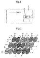
- a card 1 such as a credit card, for example, on which a hologram seal 2 is provided.
- the hologram seal 2 is formed with an image 4 composed of grid patterns 3.
- an authenticity discriminating apparatus in which the authenticity discrimination of card is performed on the basis of peak strength of light intensity distribution of the reflected diffraction light, a position of center of mass for the distribution, a width of its spread, number of peaks and so on by projecting a measuring beam onto the hologram seal and receiving a reflected diffraction light based on the measuring beam reflected on the hologram seal by a light receiving element (for example, see Japanese Patent Application No. 2000-118067).
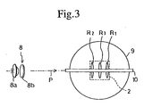
- a grid pattern 5 having diffraction gratings 3' with a predetermined width of pitch Q1 and grid patterns 6 and 7 having diffraction gratings 3' with the same direction of arrays as the former gratings but predetermined different widths of pitches Q2 and Q3 are alternatively arranged with a constant cycle, as shown in Fig. 2.
- they are Q1 > Q3 > Q2.
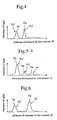
- a measuring beam P as a parallel beam is projected onto the hologram seal 2 of the kind as above described from a measuring-light projecting system 8 shown in Fig. 3, reflected diffraction lights R1, R2 and R3 are generated by the hologram seal 2 based on the measuring beam.
- the reflected diffraction light R1 is based on the grid pattern 5
- the reflected diffraction light R2 is based on the grid pattern 6
- the reflected diffraction light R3 is based on the grid pattern 7, respectively.
- the respective reflected diffraction lights R1, R2 and R3 are detected by a line sensor 10 as a light receiving element through a Fourier transformation lens 9.
- a peak strength of the light intensity distribution and width of its spread of the respective reflected diffraction lights R1, R2 and R3 on the basis of output of the received light on the respective elements of the line sensor 10 by a calculating means (not shown in the drawings), the discrimination of authenticity of the card can be performed.
- reference numeral 8a in Fig. 3 denotes a semiconductor laser.
- Reference numeral 8b denotes a collimating lens by which a divergent beam exited from the semiconductor laser 8a is transformed into a parallel beam.
- the measuring beam P is not always projected on all of the three grid patterns 5, 6 and 7.
- reference symbol (a) in Fig. 2 when the measuring beam P is projected only on the both of grid patterns 6 and 7 and not on the grid pattern 5, only the light intensity distribution R2' of the reflected diffraction lights R2 corresponding to the grid pattern 6 and the light intensity distribution R3' of the reflected diffraction lights R3 corresponding to the grid pattern 7 are obtained and the light intensity distribution R1' of the reflected diffraction lights R1 corresponding to the grid pattern 5 is not obtained on the line sensor 10 as shown in Fig. 4.
- a peak Pe of the light intensity distribution R2' and a peak Pe of the light intensity distribution R3' are made different because of a difference between a projected area of the grid pattern 6 and a projected area of the grid pattern 7 by the measuring beam P.
- the authenticity of the card can not be objectively discriminated because the distribution of light intensity of the reflected diffraction light are changed by a illuminated position to the grid patterns 5, 6 and 7, even when the measuring beam P is projected onto the hologram seal 2 of this kind.
- the present invention has been made in consideration of the above circumstances and it is an object of the present invention to provide an authenticity discriminating apparatus even for a card having a hologram seal in that a grid pattern with diffraction gratings of a predetermined pitch and grid patterns having diffraction gratings with the same directions of array as the former gratings but predetermined different pitches are alternatively arranged in a constant cycle.
- An apparatus for discriminating authenticity of a card as recited in claim 1 is characterized by including: a measuring light projecting system which projects a measuring beam from a predetermined direction onto a hologram formed on a predetermined position on the card; a light receiving element to receive reflected diffraction light based on the measuring beam which is reflected on the hologram; an averaging means to average a received light signal which corresponds to a distribution of light intensity on the light receiving element by varying a projecting position on the hologram of the measuring beam of light; and a discriminating means to discriminate the authenticity of the card by a comparison of output of the averaging means with an allowable value.
- An apparatus for discriminating authenticity of a card as recited in claim 2 is characterized in that the averaging means is composed of a totalizing means to totalize the received light signals.
- An apparatus for discriminating authenticity of a card as recited in claim 3 is characterized by further including a card conveying means and characterized in that the averaging means averages the received light signals on a basis of received light signals of the light receiving element while the card is conveyed.
- An apparatus for discriminating authenticity of a card as recited in claim 4 is characterized by discriminating the authenticity of a card having a hologram seal in that a grid pattern having diffraction gratings of a predetermined width of pitch and at least one grid pattern having diffraction gratings whose direction of array is identical with the former diffraction gratings but whose predetermined width of pitch is different are alternatively arranged in a predetermined cycle.
- An apparatus for discriminating authenticity of a card as recited in claim 5 is characterized in that the card has a hologram seal and in that a grid pattern with diffraction gratings of a predetermined width of pitch and at least one grid pattern with diffraction gratings whose direction of array is identical with the former gratings but whose predetermined width of pitch is different are alternatively arranged in a predetermined cycle, and characterized by including: a measuring light projecting system having a semiconductor laser which generates a laser beam and a collimating lens which transforms the laser beam into parallel as a measuring beam of light and which projects the measuring beam of light onto the hologram seal; a reflected diffraction light detecting system having a line sensors which receives reflected diffraction light reflected by the hologram seal and a Fourier transforming lens which is arranged between the card and the line sensor to detect the reflected diffraction light reflected by the hologram seal; a projecting position varying means which varies a
- An apparatus for discriminating authenticity of a card as recited in claim 6 is characterized in that an arrangement of the grid patterns is formed along a direction in which the line sensor is extending in the apparatus in claim 5.
- An apparatus for discriminating authenticity of a card as recited in claim 7 is characterized in that a plurality of grid patterns arranged along a direction in which the line sensor is extending are formed such that the formed positions of respective grid patterns corresponding to each other are shifted in a direction perpendicular to the direction in which the line sensor is extending and the direction in which the line sensor is extending, in the apparatus in claim 6.
- An apparatus for discriminating authenticity of a card as recited in claim 8 is characterized in that the projecting position varying means is a conveying means which conveys the card along a direction perpendicular to the direction in which the line sensor is extending, in the apparatus in claim 7.
- An apparatus for discriminating authenticity of a card as recited in claim 9 is characterized in that the projecting position varying means is a driving means which drives the measuring light projecting system and the reflected diffraction light detecting system along a direction perpendicular to the direction in which the line sensor is extending, in the apparatus in claim 7.
- An apparatus for discriminating authenticity of a card as recited in claim 10 is characterized in that the totalizing means respectively totalizes received light output of respective light receiving elements obtained while the card is conveyed, and averages distributions characteristics of light intensity corresponding to the respective grid patterns, in the apparatus in claim 8.
- Fig. 7 is a perspective view to show one example of an apparatus for discriminating authenticity of a card in accordance with the present invention, in which reference numeral 20 designates a box in the apparatus.
- the box 20 is provided with a loading slot 21 for the card 1 and a display panel 22 to show an authenticity of the card 1 is provided on an upper portion of the box. It is supposed that grid patterns 5, 6, 7 are formed on the card 1 as shown in Fig. 4.
- the card 1 is dragged into the box 20 by a card conveying means which is not shown in the drawings, and after the discrimination for authenticity has been completed the card 1 is automatically discharged.
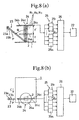
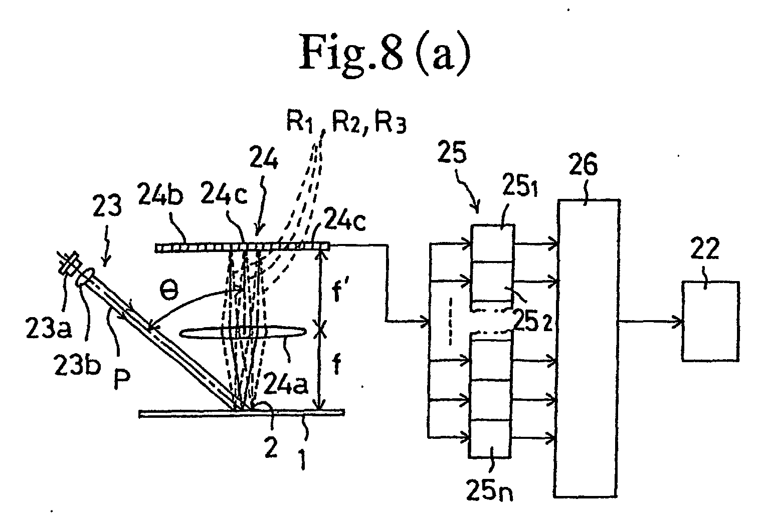
- the measuring light projecting system 23 is composed of a semiconductor laser 23a and a collimating lens 23b.
- the collimating lens 23b performs a function to transform a laser beam which is exited from the semiconductor laser 23a into a parallel light beam and to project a measuring beam P onto the card 1.
- the reflected diffraction light detecting system 24 is composed of a Fourier transforming lens 24a and a line sensor 24b as a light receiving element.
- the card 1 is dragged into the box 20 and set at a front focusing position f of the Fourier transforming lens 24a.
- the measuring beam P is projected from a direction in which the line sensor 24b is extending as shown in Fig. 8 (b) in a manner that an incident angle " of the measuring beam P is maintained constantly with respect to the hologram seal 2 as shown in Fig. 8 (a) to form the reflected diffraction lights R1, R2 and R3 as shown in Fig. 9 with enlargement.
- the card 1 has the hologram seal 2 in which a grid pattern 5 having diffraction gratings 3 of a predetermined pitch Q1 and grid patterns 6, 7 having diffraction gratings 3' whose directions of array are identical with the diffraction gratings 3 but whose respective predetermined different pitches Q2, Q3 are different from the pitch Q1 are alternatively arranged in a constant cycle as shown in Fig. 10.
- these grid patterns 5, 6 and 7, a plurality of patterns are formed along a direction in which the line sensor 24b is extending.
- a plurality of patterns are formed such that the formed positions of respective grid patterns 5, 6, 7 corresponding to each other are shifted in a direction perpendicular to the direction in which the line sensor 24b is extending and at the same time in the direction in which the line sensor 24b is extending.
- the card conveying means functions as a projecting position varying means by which the projected position by the measuring beam for the hologram seal 2 is varied in order to obtain an averaged value of the respective distributions of light intensity at the line sensor 24b generated by the reflected diffraction light of grid patterns 5, 6 and 7.
- Fig. 11 (a) shows the distribution of light intensity when the spot S is located on a position designated by the reference symbol (a) in Fig. 10
- Fig. 11 (b) shows the distribution of light intensity when the spot S is located on a position designated by the reference symbol (b) in Fig. 10
- Fig. 11 (c) shows the distribution of light intensity when the spot S is located on a position designated by the reference symbol (c) in Fig. 10.
- the respective totalizing elements 251 to 25n of totalizing circuit 25 totalize the respective received light signals from when the card 1 is inserted into the box 20 and until the card is discharged from the box 20.
- the received light signals generated by many numbers of grid patterns 5, 6, 7 which are formed periodically along the direction of card conveyance are totalized with the respective totalizing elements 251 to 25n while the card 1 is conveyed.
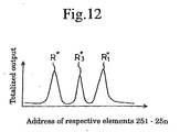
- totalized output R1", R2" and R3" of the distribution of light intensity R1', R2' and R3' generated by the respective grid patterns 5, 6 and 7 can be obtained as shown in Fig. 12 and thereby the respective distributions of light intensity can be averaged.
- the outputs of respective totalizing elements 251 to 25n are input into a discriminating means 26 for the discriminating means 26 to perform the authenticity discriminating of the card 1 by a comparison of the output of totalizing circuit 25 with a predetermined reference value.
- the predetermined reference value for example, presence or absence of the light intensity distribution, the peak strength of light intensity distribution and the width of its spread are used and a result of the discrimination is displayed on the display panel 22.
- the card 1 is conveyed with respect to the fixed measuring light projecting system 23 and reflected diffraction light detecting system 24 to average the received light signals while the card is conveyed
- a moving means causing the measuring light projecting system 23 and the reflected diffraction light detecting system 24 to move integrally with respect to the fixed card 1 is used as the projecting position varying means to average the received light signals while the projecting position varying means is moved.
- an apparatus for discriminating authenticity of a card having a hologram in that a grid pattern having diffraction grating of a predetermined width of pitch and grid patterns having diffraction gratings whose directions of array are same to each other but whose respective predetermined widths of pitches are different are alternatively arranged in a predetermined cycle.
Landscapes
- Physics & Mathematics (AREA)
- Engineering & Computer Science (AREA)
- General Physics & Mathematics (AREA)
- General Health & Medical Sciences (AREA)
- Health & Medical Sciences (AREA)
- Toxicology (AREA)
- Electromagnetism (AREA)
- Theoretical Computer Science (AREA)
- Artificial Intelligence (AREA)
- Computer Vision & Pattern Recognition (AREA)
- Computer Security & Cryptography (AREA)
- Holo Graphy (AREA)
- Credit Cards Or The Like (AREA)
- Inspection Of Paper Currency And Valuable Securities (AREA)
Abstract
An apparatus for discriminating authenticity of a card according to
the present invention comprising measuring light projecting system 23
which projects a measuring beam of light P from a predetermined direction
onto a hologram 2 formed on a predetermined position on a card 1, a light
receiving element 24b which receives reflected diffraction light R1, R2 and
R3 generated by the measuring beam of light P reflected on the hologram 2,
an averaging means 25 which varies projecting position of the measuring
beam of light P to average received light signals corresponding to
distribution characteristics of light intensity on the light receiving element
24b, and a discriminating means 26 to discriminate authenticity for the card
by a comparison of output from the averaging means 25 with an allowable
value.
Description
- The present invention relates to an apparatus for discriminating authenticity of a card having a hologram.
- Up to now, as shown in Fig. 1, there is known a
card 1 such as a credit card, for example, on which ahologram seal 2 is provided. Thehologram seal 2 is formed with animage 4 composed ofgrid patterns 3. - In the past, authenticity of the
card 1 has been discriminated by the naked eye. However, it is difficult to discriminate objectively the authenticity of thecard 1 by viewing the image formed on thehologram seal 2 with the naked eye, because theimage 4 may be varied in response to a direction of incident light onto the card or there may be formed scratch on thecard 1. - Recently, to objectively discriminate the authenticity of
card 1, there is being developed an authenticity discriminating apparatus in which the authenticity discrimination of card is performed on the basis of peak strength of light intensity distribution of the reflected diffraction light, a position of center of mass for the distribution, a width of its spread, number of peaks and so on by projecting a measuring beam onto the hologram seal and receiving a reflected diffraction light based on the measuring beam reflected on the hologram seal by a light receiving element (for example, see Japanese Patent Application No. 2000-118067). - However, in the
hologram seal 2 there is one in which agrid pattern 5 having diffraction gratings 3' with a predetermined width of pitch Q1 andgrid patterns - When a measuring beam P as a parallel beam is projected onto the
hologram seal 2 of the kind as above described from a measuring-light projecting system 8 shown in Fig. 3, reflected diffraction lights R1, R2 and R3 are generated by thehologram seal 2 based on the measuring beam. - Here, the reflected diffraction light R1 is based on the
grid pattern 5, the reflected diffraction light R2 is based on thegrid pattern 6 and the reflected diffraction light R3 is based on thegrid pattern 7, respectively. - The respective reflected diffraction lights R1, R2 and R3 are detected by a
line sensor 10 as a light receiving element through a Fouriertransformation lens 9. By obtaining presence or absence of light intensity distribution, a peak strength of the light intensity distribution and width of its spread of the respective reflected diffraction lights R1, R2 and R3 on the basis of output of the received light on the respective elements of theline sensor 10 by a calculating means (not shown in the drawings), the discrimination of authenticity of the card can be performed. - Note that
reference numeral 8a in Fig. 3 denotes a semiconductor laser.Reference numeral 8b denotes a collimating lens by which a divergent beam exited from thesemiconductor laser 8a is transformed into a parallel beam. - By the way, noting a spot S of the measuring beam P on the
hologram seal 2 of this kind, the measuring beam P is not always projected on all of the threegrid patterns grid patterns grid pattern 5, only the light intensity distribution R2' of the reflected diffraction lights R2 corresponding to thegrid pattern 6 and the light intensity distribution R3' of the reflected diffraction lights R3 corresponding to thegrid pattern 7 are obtained and the light intensity distribution R1' of the reflected diffraction lights R1 corresponding to thegrid pattern 5 is not obtained on theline sensor 10 as shown in Fig. 4. At the same time a peak Pe of the light intensity distribution R2' and a peak Pe of the light intensity distribution R3' are made different because of a difference between a projected area of thegrid pattern 6 and a projected area of thegrid pattern 7 by the measuring beam P. - On the other hand, when the projected area of the
grid pattern 6 by the measuring beam P is much larger than those of theother grid patterns respective grid patterns grid patterns line sensor 10 as shown in Fig. 5, height of two peaks Pe for the distribution of light intensity R1' and R3' generated by thegrid patterns grid pattern 6. - For example, in other case, as shown at reference symbol (c) in Fig. 2, when the measuring beam P is projected only on the both of
grid patterns grid pattern 7, only the light intensity distribution R1' of the reflected diffraction lights R1 corresponding to thegrid pattern 5 and the light intensity distribution R2' of the reflected diffraction lights R2 corresponding to thegrid pattern 6 are obtained and the light intensity distribution R3' of the reflected diffraction lights R3 corresponding to thegrid pattern 7 is not obtained on theline sensor 10 as shown in Fig. 6. - Accordingly, the authenticity of the card can not be objectively discriminated because the distribution of light intensity of the reflected diffraction light are changed by a illuminated position to the
grid patterns hologram seal 2 of this kind. - The present invention has been made in consideration of the above circumstances and it is an object of the present invention to provide an authenticity discriminating apparatus even for a card having a hologram seal in that a grid pattern with diffraction gratings of a predetermined pitch and grid patterns having diffraction gratings with the same directions of array as the former gratings but predetermined different pitches are alternatively arranged in a constant cycle.
- An apparatus for discriminating authenticity of a card as recited in
claim 1 is characterized by including: a measuring light projecting system which projects a measuring beam from a predetermined direction onto a hologram formed on a predetermined position on the card; a light receiving element to receive reflected diffraction light based on the measuring beam which is reflected on the hologram; an averaging means to average a received light signal which corresponds to a distribution of light intensity on the light receiving element by varying a projecting position on the hologram of the measuring beam of light; and a discriminating means to discriminate the authenticity of the card by a comparison of output of the averaging means with an allowable value. - An apparatus for discriminating authenticity of a card as recited in
claim 2 is characterized in that the averaging means is composed of a totalizing means to totalize the received light signals. - An apparatus for discriminating authenticity of a card as recited in
claim 3 is characterized by further including a card conveying means and characterized in that the averaging means averages the received light signals on a basis of received light signals of the light receiving element while the card is conveyed. - An apparatus for discriminating authenticity of a card as recited in
claim 4 is characterized by discriminating the authenticity of a card having a hologram seal in that a grid pattern having diffraction gratings of a predetermined width of pitch and at least one grid pattern having diffraction gratings whose direction of array is identical with the former diffraction gratings but whose predetermined width of pitch is different are alternatively arranged in a predetermined cycle. - An apparatus for discriminating authenticity of a card as recited in
claim 5 is characterized in that the card has a hologram seal and in that a grid pattern with diffraction gratings of a predetermined width of pitch and at least one grid pattern with diffraction gratings whose direction of array is identical with the former gratings but whose predetermined width of pitch is different are alternatively arranged in a predetermined cycle, and characterized by including: a measuring light projecting system having a semiconductor laser which generates a laser beam and a collimating lens which transforms the laser beam into parallel as a measuring beam of light and which projects the measuring beam of light onto the hologram seal; a reflected diffraction light detecting system having a line sensors which receives reflected diffraction light reflected by the hologram seal and a Fourier transforming lens which is arranged between the card and the line sensor to detect the reflected diffraction light reflected by the hologram seal; a projecting position varying means which varies a projecting position on the hologram seal of the measuring beam to obtain distribution characteristics of light intensity generated by reflected diffraction light from the respective grid patterns on the line sensor in an averaged form; a totalizing means to which received light signals from respective elements of the line sensor are input and which respectively totalizes the received light signals from the respective elements; and a discriminating means which discriminates the authenticity of the card by comparison of output from the totalizing means with an allowable value. - An apparatus for discriminating authenticity of a card as recited in
claim 6 is characterized in that an arrangement of the grid patterns is formed along a direction in which the line sensor is extending in the apparatus inclaim 5. - An apparatus for discriminating authenticity of a card as recited in
claim 7 is characterized in that a plurality of grid patterns arranged along a direction in which the line sensor is extending are formed such that the formed positions of respective grid patterns corresponding to each other are shifted in a direction perpendicular to the direction in which the line sensor is extending and the direction in which the line sensor is extending, in the apparatus inclaim 6. - An apparatus for discriminating authenticity of a card as recited in
claim 8 is characterized in that the projecting position varying means is a conveying means which conveys the card along a direction perpendicular to the direction in which the line sensor is extending, in the apparatus inclaim 7. - An apparatus for discriminating authenticity of a card as recited in
claim 9 is characterized in that the projecting position varying means is a driving means which drives the measuring light projecting system and the reflected diffraction light detecting system along a direction perpendicular to the direction in which the line sensor is extending, in the apparatus inclaim 7. - An apparatus for discriminating authenticity of a card as recited in
claim 10 is characterized in that the totalizing means respectively totalizes received light output of respective light receiving elements obtained while the card is conveyed, and averages distributions characteristics of light intensity corresponding to the respective grid patterns, in the apparatus inclaim 8. -
- Fig. 1 is a plan view to show one example of card having a hologram seal.
- Fig. 2 is an explanatory diagram to show a grid pattern which is formed on a hologram seal.
- Fig. 3 is an explanatory diagram to show a reflected diffraction light which is generated by projection of a measuring beam onto the hologram seal.
- Fig. 4 is an explanatory diagram to show a distribution of light intensity when a spot of measuring beam is formed on a position (a) designated in Fig. 2 in the grid pattern.
- Fig. 5 is an explanatory diagram to show a distribution of light intensity when a spot of measuring beam is formed on a position (b) designated in Fig. 2 in the grid pattern.
- Fig. 6 is an explanatory diagram to show a distribution of light intensity when a spot of measuring beam is formed on a position (c) designated in Fig. 2 in the grid pattern.
- Fig. 7 is a perspective view to show a box of the authenticity discriminating apparatus for card in accordance with the present invention.
- Fig. 8 are optical diagrams to show a measuring light projecting system and a reflected diffraction light detecting system both of which are set up in the box shown in Fig. 7, in that Fig. 8 (a) is a front view and Fig. 8 (b) is a plan view.
- Fig. 9 is an explanatory diagram to show a reflected diffraction light which is generated by the measuring light projecting system shown in Fig. 8.
- Fig. 10 is an explanatory diagram to show a variation of position of the spot on the hologram seal.
- Fig. 11 is an explanatory diagram to show a distribution of light intensity which is changed corresponding to the variation of position of the spot on the hologram seal.
- Fig. 12 is an explanatory diagram to show a distribution of averaged totalizing output.
-
- Fig. 7 is a perspective view to show one example of an apparatus for discriminating authenticity of a card in accordance with the present invention, in which
reference numeral 20 designates a box in the apparatus. Thebox 20 is provided with aloading slot 21 for thecard 1 and adisplay panel 22 to show an authenticity of thecard 1 is provided on an upper portion of the box. It is supposed thatgrid patterns card 1 as shown in Fig. 4. - The
card 1 is dragged into thebox 20 by a card conveying means which is not shown in the drawings, and after the discrimination for authenticity has been completed thecard 1 is automatically discharged. - A measuring
light projecting system 23 and a reflected diffractionlight detecting system 24 which are shown in Fig. 8 are provided in thebox 20. - The measuring
light projecting system 23 is composed of asemiconductor laser 23a and acollimating lens 23b. Thecollimating lens 23b performs a function to transform a laser beam which is exited from thesemiconductor laser 23a into a parallel light beam and to project a measuring beam P onto thecard 1. - The reflected diffraction
light detecting system 24 is composed of a Fourier transforminglens 24a and aline sensor 24b as a light receiving element. Thecard 1 is dragged into thebox 20 and set at a front focusing position f of the Fourier transforminglens 24a. Theline sensor 24b is set at a back focusing position f' (f = f') of the Fourier transforminglens 24a. - When the
semiconductor laser 23a is turned on by a manipulation of a switch which is not shown in the drawings, the measuring beam P is projected from a direction in which theline sensor 24b is extending as shown in Fig. 8 (b) in a manner that an incident angle " of the measuring beam P is maintained constantly with respect to thehologram seal 2 as shown in Fig. 8 (a) to form the reflected diffraction lights R1, R2 and R3 as shown in Fig. 9 with enlargement. - The
card 1 has thehologram seal 2 in which agrid pattern 5 havingdiffraction gratings 3 of a predetermined pitch Q1 andgrid patterns diffraction gratings 3 but whose respective predetermined different pitches Q2, Q3 are different from the pitch Q1 are alternatively arranged in a constant cycle as shown in Fig. 10. - As arrangement of these
grid patterns line sensor 24b is extending. As arrangement of thegrid patterns line sensor 24b is extending, a plurality of patterns are formed such that the formed positions ofrespective grid patterns line sensor 24b is extending and at the same time in the direction in which theline sensor 24b is extending. - When the
card 1 is conveyed by the card conveying means (not shown) to be dragged in a direction shown in an arrow C (direction that ditches of diffraction gratings 3' are extending), a position of spot S on thegrid patterns hologram seal 2 is relatively deflected with respect to thegrid patterns light receiving elements 24c of theline sensor 24b are continuously varied in accordance with dragging of thecard 1. - In other words, the card conveying means functions as a projecting position varying means by which the projected position by the measuring beam for the
hologram seal 2 is varied in order to obtain an averaged value of the respective distributions of light intensity at theline sensor 24b generated by the reflected diffraction light ofgrid patterns - Here, Fig. 11 (a) shows the distribution of light intensity when the spot S is located on a position designated by the reference symbol (a) in Fig. 10, Fig. 11 (b) shows the distribution of light intensity when the spot S is located on a position designated by the reference symbol (b) in Fig. 10 and Fig. 11 (c) shows the distribution of light intensity when the spot S is located on a position designated by the reference symbol (c) in Fig. 10.
- The respective received light signals which are output from respective
light receiving elements 24c (n = 1 to n) of theline sensor 24b are respectively input into respectivetotalizing elements 251 to 25n of a totalizingcircuit 25. The respectivetotalizing elements 251 to 25n of totalizingcircuit 25 totalize the respective received light signals from when thecard 1 is inserted into thebox 20 and until the card is discharged from thebox 20. - Accordingly, the received light signals generated by many numbers of
grid patterns totalizing elements 251 to 25n while thecard 1 is conveyed. By this arrangement, totalized output R1", R2" and R3" of the distribution of light intensity R1', R2' and R3' generated by therespective grid patterns - The outputs of respective
totalizing elements 251 to 25n are input into a discriminating means 26 for the discriminating means 26 to perform the authenticity discriminating of thecard 1 by a comparison of the output of totalizingcircuit 25 with a predetermined reference value. - As the predetermined reference value, for example, presence or absence of the light intensity distribution, the peak strength of light intensity distribution and the width of its spread are used and a result of the discrimination is displayed on the
display panel 22. - Note that in the embodiment described above, although the
card 1 is conveyed with respect to the fixed measuring light projectingsystem 23 and reflected diffractionlight detecting system 24 to average the received light signals while the card is conveyed, alternatively, it may be also recommendable that a moving means causing the measuring light projectingsystem 23 and the reflected diffractionlight detecting system 24 to move integrally with respect to thefixed card 1 is used as the projecting position varying means to average the received light signals while the projecting position varying means is moved. - In accordance with the present invention, there is provided an apparatus for discriminating authenticity of a card having a hologram in that a grid pattern having diffraction grating of a predetermined width of pitch and grid patterns having diffraction gratings whose directions of array are same to each other but whose respective predetermined widths of pitches are different are alternatively arranged in a predetermined cycle.
Claims (10)
- An apparatus for discriminating authenticity of a card comprising:a measuring-light projecting system which projects a measuring beam from a predetermined direction onto a hologram formed on a predetermined position on said card;a light receiving element for receiving reflected diffraction light based on said measuring beam which is reflected on said hologram;an averaging means to average a received light signal which corresponds to a distribution of light intensity on the light receiving element by varying a projecting position on said hologram of said measuring beam; anda discriminating means to discriminate the authenticity of said card by a comparison of output of said averaging means with a predetermined reference value.
- An apparatus for discriminating authenticity of a card according to claim 1, characterized in that said averaging means is composed of a totalizing means to totalize said received light signals.
- An apparatus for discriminating authenticity of a card according to claim 1 or claim 2, characterized by further including a card conveying means and characterized in that said averaging means averages said received light signals on a basis of received light signals generated by said light receiving element while said card is conveyed.
- An apparatus for discriminating authenticity of a card according to claim 1, characterized by discriminating the authenticity of a card having a hologram seal in that a grid pattern having diffraction gratings of a predetermined width of pitch and at least one grid pattern having diffraction gratings whose direction of array is same as said former diffraction gratings but whose predetermined width of pitch is different are alternatively arranged in a predetermined cycle.
- An apparatus for discriminating authenticity of a card having a hologram in which a grid pattern having diffraction gratings of a predetermined width of pitch and at least one grid pattern having diffraction gratings whose direction of array is same as said former diffraction gratings but whose predetermined width of pitch is different are alternatively arranged in a predetermined cycle, characterized by including:a measuring light projecting system having a semiconductor laser which generates a laser beam and a collimating lens which transforms said laser beam into parallel as a measuring beam and which projects the measuring beam onto said hologram seal;a reflected diffraction light detecting system having a line sensors which receives reflected diffraction light reflected by said hologram seal and a Fourier transforming lens which is arranged between said card and said line sensor to detect the reflected diffraction light reflected by said hologram seal;a projecting position varying means which varies a projecting position on said hologram seal of said measuring beam of light to obtain a set of distribution characteristics of light intensity generated by reflected diffraction light from said respective grid patterns on said line sensor in an averaged form;a totalizing means to which received light signals from respective elements of said line sensor are input and which respectively totalizes the received light signals from the respective elements; anda discriminating means which discriminates an authenticity of said card by comparison of output from said totalizing means with a predetermined reference value.
- An apparatus for discriminating authenticity of a card according to claim 5, characterized in that an arrangement of said grid patterns is formed along a direction in which said line sensor is extending.
- An apparatus for discriminating authenticity of a card according to claim 6, characterized in that a plurality of arrangements of said grid patterns formed along a direction in which said line sensor is extending are formed such that the formed positions of respective grid patterns corresponding to each other are shifted in a direction perpendicular to said direction in which said line sensor is extending and the direction in which said line sensor is extending.
- An apparatus for discriminating authenticity of a card according to claim 7, characterized in that said projecting position varying means is a conveying means which conveys said card along a direction perpendicular to the direction in which said line sensor is extending.
- An apparatus for discriminating authenticity of a card according to claim 7, characterized in that said projecting position varying means is a driving means which drives said measuring light projecting system and said reflected diffraction light detecting system along a direction perpendicular to the direction in which said line sensor is extending.
- An apparatus for discriminating authenticity of a card according to claim 8, characterized in that said totalizing means respectively totalizes received light output of respective light receiving elements obtained while said card is conveyed, and averages distributions characteristics of light intensity corresponding to the respective grid patterns.
Applications Claiming Priority (3)
| Application Number | Priority Date | Filing Date | Title |
|---|---|---|---|
| JP2001089336 | 2001-03-27 | ||
| JP2001089336A JP2002288604A (en) | 2001-03-27 | 2001-03-27 | Card authentication device |
| PCT/JP2002/001346 WO2002076761A1 (en) | 2001-03-27 | 2002-02-18 | Card true/false decision apparatus |
Publications (1)
| Publication Number | Publication Date |
|---|---|
| EP1291199A1 true EP1291199A1 (en) | 2003-03-12 |
Family
ID=18944276
Family Applications (1)
| Application Number | Title | Priority Date | Filing Date |
|---|---|---|---|
| EP02712412A Withdrawn EP1291199A1 (en) | 2001-03-27 | 2002-02-18 | Card true/false decision apparatus |
Country Status (8)
| Country | Link |
|---|---|
| US (1) | US20040016810A1 (en) |
| EP (1) | EP1291199A1 (en) |
| JP (1) | JP2002288604A (en) |
| KR (1) | KR20030017978A (en) |
| CN (1) | CN1460073A (en) |
| CA (1) | CA2416720A1 (en) |
| TW (1) | TW580639B (en) |
| WO (1) | WO2002076761A1 (en) |
Cited By (2)
| Publication number | Priority date | Publication date | Assignee | Title |
|---|---|---|---|---|
| WO2005066902A1 (en) * | 2004-01-09 | 2005-07-21 | Securency Pty Limited | Method and apparatus for inspection of security articles |
| AU2005204064B2 (en) * | 2004-01-09 | 2008-01-10 | Securency International Pty Ltd | Method and apparatus for inspection of security articles |
Families Citing this family (17)
| Publication number | Priority date | Publication date | Assignee | Title |
|---|---|---|---|---|
| US8171567B1 (en) | 2002-09-04 | 2012-05-01 | Tracer Detection Technology Corp. | Authentication method and system |
| RU2380750C2 (en) | 2004-03-12 | 2010-01-27 | Инджениа Текнолоджи Лимитед | Methods and devices for creation of printing products with possibility of their identification and their subsequent verification |
| JP4607947B2 (en) | 2004-03-12 | 2011-01-05 | インジェニア・ホールディングス・(ユー・ケイ)・リミテッド | Authenticity verification methods, products and equipment |
| GB2417592B (en) | 2004-08-13 | 2006-07-26 | Ingenia Technology Ltd | Authenticity verification of articles |
| GB2444139B (en) * | 2004-08-13 | 2008-11-12 | Ingenia Technology Ltd | Authenticity verification methods products and apparatuses |
| EP1908027B1 (en) | 2005-07-27 | 2010-09-29 | Ingenia Holdings Limited | Verification of authenticity |
| GB2448245B (en) | 2005-12-23 | 2009-11-04 | Ingenia Holdings | Optical authentication |
| DE102006012991A1 (en) * | 2006-03-22 | 2007-10-11 | Bayer Innovation Gmbh | Method and device for optically reading information |
| GB2460625B (en) * | 2008-05-14 | 2010-05-26 | Ingenia Holdings | Two tier authentication |
| RU2382411C1 (en) * | 2008-07-10 | 2010-02-20 | Фаля Юрьевич Писаренко | Method of extending service life and improving security from forgery of bank cards, banknotes and other security papers with rectangular shape |
| GB2466465B (en) | 2008-12-19 | 2011-02-16 | Ingenia Holdings | Authentication |
| GB2466311B (en) * | 2008-12-19 | 2010-11-03 | Ingenia Holdings | Self-calibration of a matching algorithm for determining authenticity |
| GB2476226B (en) | 2009-11-10 | 2012-03-28 | Ingenia Holdings Ltd | Optimisation |
| US8433124B2 (en) * | 2010-01-07 | 2013-04-30 | De La Rue North America Inc. | Systems and methods for detecting an optically variable material |
| CN102708395B (en) * | 2012-04-23 | 2014-11-26 | 东港安全印刷股份有限公司 | Three-dimensional anti-counterfeiting IC (intelligent circuit) card |
| GB2524989B (en) * | 2014-04-08 | 2018-12-26 | Innovia Films Ltd | Apparatus and method |
| US20180231697A1 (en) | 2015-08-07 | 2018-08-16 | Rolic Technologies AG | Azimuthally modulated scattering device |
Family Cites Families (12)
| Publication number | Priority date | Publication date | Assignee | Title |
|---|---|---|---|---|
| CH653459A5 (en) * | 1981-04-16 | 1985-12-31 | Landis & Gyr Ag | DOCUMENT WITH A SECURITY THREAD AND METHOD for currency authentication SAME. |
| JP2736808B2 (en) * | 1988-08-12 | 1998-04-02 | ローレルバンクマシン 株式会社 | Paper sheet identification device |
| JPH05266243A (en) * | 1991-12-20 | 1993-10-15 | Matsushita Electric Ind Co Ltd | Information media and information media reader |
| JPH05289599A (en) * | 1992-04-13 | 1993-11-05 | Dainippon Printing Co Ltd | How to transfer and use the code part |
| JP3563774B2 (en) * | 1994-05-27 | 2004-09-08 | 大日本印刷株式会社 | Information recording medium |
| JPH07304286A (en) * | 1994-08-12 | 1995-11-21 | Dainippon Printing Co Ltd | Hologram card |
| JP3741777B2 (en) * | 1996-04-15 | 2006-02-01 | グローリー工業株式会社 | Paper sheet identification method |
| JPH09311109A (en) * | 1996-05-22 | 1997-12-02 | Matsushita Electric Ind Co Ltd | Defect inspection method using light and its apparatus |
| JPH11180079A (en) * | 1997-12-25 | 1999-07-06 | Dainippon Printing Co Ltd | Information recording medium and its authentication method |
| JP2000118067A (en) | 1998-10-15 | 2000-04-25 | Brother Ind Ltd | Recording device |
| JP4336008B2 (en) * | 1998-11-17 | 2009-09-30 | 日本発條株式会社 | Object identification structure and identification method |
| US6473165B1 (en) * | 2000-01-21 | 2002-10-29 | Flex Products, Inc. | Automated verification systems and methods for use with optical interference devices |
-
2001
- 2001-03-27 JP JP2001089336A patent/JP2002288604A/en active Pending
-
2002
- 2002-02-18 EP EP02712412A patent/EP1291199A1/en not_active Withdrawn
- 2002-02-18 US US10/416,415 patent/US20040016810A1/en not_active Abandoned
- 2002-02-18 CA CA002416720A patent/CA2416720A1/en not_active Abandoned
- 2002-02-18 CN CN02800840A patent/CN1460073A/en active Pending
- 2002-02-18 KR KR1020027015836A patent/KR20030017978A/en not_active Abandoned
- 2002-02-18 WO PCT/JP2002/001346 patent/WO2002076761A1/en not_active Ceased
- 2002-02-22 TW TW091103194A patent/TW580639B/en not_active IP Right Cessation
Non-Patent Citations (1)
| Title |
|---|
| See references of WO02076761A1 * |
Cited By (3)
| Publication number | Priority date | Publication date | Assignee | Title |
|---|---|---|---|---|
| WO2005066902A1 (en) * | 2004-01-09 | 2005-07-21 | Securency Pty Limited | Method and apparatus for inspection of security articles |
| AU2005204064B2 (en) * | 2004-01-09 | 2008-01-10 | Securency International Pty Ltd | Method and apparatus for inspection of security articles |
| US7652757B2 (en) | 2004-01-09 | 2010-01-26 | Securency International Pty Ltd | Method and apparatus for inspection of security articles incorporating a diffractive optical projection element |
Also Published As
| Publication number | Publication date |
|---|---|
| CN1460073A (en) | 2003-12-03 |
| CA2416720A1 (en) | 2002-12-02 |
| WO2002076761A1 (en) | 2002-10-03 |
| US20040016810A1 (en) | 2004-01-29 |
| KR20030017978A (en) | 2003-03-04 |
| JP2002288604A (en) | 2002-10-04 |
| TW580639B (en) | 2004-03-21 |
Similar Documents
| Publication | Publication Date | Title |
|---|---|---|
| US20040016810A1 (en) | Card true/false decision apparatus | |
| EP1049054B1 (en) | Coin discriminating apparatus | |
| US7205521B2 (en) | Speckle based sensor for three dimensional navigation | |
| JP6046929B2 (en) | Optical measuring device | |
| EP1077434B1 (en) | Coin discriminating apparatus | |
| JPS6230676B2 (en) | ||
| EP0640944A1 (en) | Coin discriminating apparatus | |
| CN1577404B (en) | A banknote validator with a reflecting optical sensor | |
| KR20020021131A (en) | Card genuine judging apparatus and card genuine judging system | |
| US20040031849A1 (en) | Card true/false decision apparatus | |
| EP1248224A2 (en) | Sheet detecting assembly and method | |
| US4410268A (en) | Apparatus for automatically measuring the characteristics of an optical system | |
| JP2001504592A (en) | Distance measuring method and distance measuring device | |
| US8120762B2 (en) | Light guide and optical sensing module input device and method for making same | |
| US20120248299A1 (en) | Apparatus for the analysis of an object, preferably of a document of value, using optical radiation | |
| US6794625B2 (en) | Dynamic automatic focusing method and apparatus using interference patterns | |
| EP3637378B1 (en) | Identification device, identification method, and identification program | |
| CN108007427B (en) | Measuring device and method for triangulation | |
| JP4221171B2 (en) | Coin identification device | |
| EP1300258A1 (en) | Card true/false decision apparatus | |
| JP2001307171A (en) | Card authentication device | |
| JPH0735545A (en) | Optical rangefinder | |
| JP2001307173A (en) | Card authentication device | |
| JP2002366891A (en) | Card authentication device | |
| US7076100B2 (en) | Method and apprartus thereof for detecting a hidden image in a hologram |
Legal Events
| Date | Code | Title | Description |
|---|---|---|---|
| PUAI | Public reference made under article 153(3) epc to a published international application that has entered the european phase |
Free format text: ORIGINAL CODE: 0009012 |
|
| 17P | Request for examination filed |
Effective date: 20021206 |
|
| AK | Designated contracting states |
Kind code of ref document: A1 Designated state(s): AT BE CH CY DE DK ES FI FR GB GR IE IT LI LU MC NL PT SE TR Designated state(s): AT BE CH CY DE DK ES FI FR GB GR IE IT LI LU MC NL PT SE TR |
|
| STAA | Information on the status of an ep patent application or granted ep patent |
Free format text: STATUS: THE APPLICATION HAS BEEN WITHDRAWN |
|
| 18W | Application withdrawn |
Effective date: 20040301 |