EP1291061A1 - Honeycomb structure and honeycomb filter, and method of producing them - Google Patents
Honeycomb structure and honeycomb filter, and method of producing them Download PDFInfo
- Publication number
- EP1291061A1 EP1291061A1 EP01936843A EP01936843A EP1291061A1 EP 1291061 A1 EP1291061 A1 EP 1291061A1 EP 01936843 A EP01936843 A EP 01936843A EP 01936843 A EP01936843 A EP 01936843A EP 1291061 A1 EP1291061 A1 EP 1291061A1
- Authority
- EP
- European Patent Office
- Prior art keywords
- honeycomb
- honeycomb structure
- face
- side end
- segments
- Prior art date
- Legal status (The legal status is an assumption and is not a legal conclusion. Google has not performed a legal analysis and makes no representation as to the accuracy of the status listed.)
- Granted
Links
Images


Classifications
-
- C—CHEMISTRY; METALLURGY
- C04—CEMENTS; CONCRETE; ARTIFICIAL STONE; CERAMICS; REFRACTORIES
- C04B—LIME, MAGNESIA; SLAG; CEMENTS; COMPOSITIONS THEREOF, e.g. MORTARS, CONCRETE OR LIKE BUILDING MATERIALS; ARTIFICIAL STONE; CERAMICS; REFRACTORIES; TREATMENT OF NATURAL STONE
- C04B37/00—Joining burned ceramic articles with other burned ceramic articles or other articles by heating
- C04B37/003—Joining burned ceramic articles with other burned ceramic articles or other articles by heating by means of an interlayer consisting of a combination of materials selected from glass, or ceramic material with metals, metal oxides or metal salts
- C04B37/005—Joining burned ceramic articles with other burned ceramic articles or other articles by heating by means of an interlayer consisting of a combination of materials selected from glass, or ceramic material with metals, metal oxides or metal salts consisting of glass or ceramic material
-
- B—PERFORMING OPERATIONS; TRANSPORTING
- B01—PHYSICAL OR CHEMICAL PROCESSES OR APPARATUS IN GENERAL
- B01D—SEPARATION
- B01D39/00—Filtering material for liquid or gaseous fluids
- B01D39/14—Other self-supporting filtering material ; Other filtering material
- B01D39/20—Other self-supporting filtering material ; Other filtering material of inorganic material, e.g. asbestos paper, metallic filtering material of non-woven wires
- B01D39/2068—Other inorganic materials, e.g. ceramics
-
- B—PERFORMING OPERATIONS; TRANSPORTING
- B01—PHYSICAL OR CHEMICAL PROCESSES OR APPARATUS IN GENERAL
- B01J—CHEMICAL OR PHYSICAL PROCESSES, e.g. CATALYSIS OR COLLOID CHEMISTRY; THEIR RELEVANT APPARATUS
- B01J35/00—Catalysts, in general, characterised by their form or physical properties
- B01J35/50—Catalysts, in general, characterised by their form or physical properties characterised by their shape or configuration
- B01J35/56—Foraminous structures having flow-through passages or channels, e.g. grids or three-dimensional [3D] monoliths
- B01J35/57—Honeycombs
-
- B—PERFORMING OPERATIONS; TRANSPORTING
- B28—WORKING CEMENT, CLAY, OR STONE
- B28B—SHAPING CLAY OR OTHER CERAMIC COMPOSITIONS; SHAPING SLAG; SHAPING MIXTURES CONTAINING CEMENTITIOUS MATERIAL, e.g. PLASTER
- B28B1/00—Producing shaped prefabricated articles from the material
- B28B1/002—Producing shaped prefabricated articles from the material assembled from preformed elements
-
- C—CHEMISTRY; METALLURGY
- C04—CEMENTS; CONCRETE; ARTIFICIAL STONE; CERAMICS; REFRACTORIES
- C04B—LIME, MAGNESIA; SLAG; CEMENTS; COMPOSITIONS THEREOF, e.g. MORTARS, CONCRETE OR LIKE BUILDING MATERIALS; ARTIFICIAL STONE; CERAMICS; REFRACTORIES; TREATMENT OF NATURAL STONE
- C04B35/00—Shaped ceramic products characterised by their composition; Ceramics compositions; Processing powders of inorganic compounds preparatory to the manufacturing of ceramic products
- C04B35/01—Shaped ceramic products characterised by their composition; Ceramics compositions; Processing powders of inorganic compounds preparatory to the manufacturing of ceramic products based on oxide ceramics
- C04B35/10—Shaped ceramic products characterised by their composition; Ceramics compositions; Processing powders of inorganic compounds preparatory to the manufacturing of ceramic products based on oxide ceramics based on aluminium oxide
-
- C—CHEMISTRY; METALLURGY
- C04—CEMENTS; CONCRETE; ARTIFICIAL STONE; CERAMICS; REFRACTORIES
- C04B—LIME, MAGNESIA; SLAG; CEMENTS; COMPOSITIONS THEREOF, e.g. MORTARS, CONCRETE OR LIKE BUILDING MATERIALS; ARTIFICIAL STONE; CERAMICS; REFRACTORIES; TREATMENT OF NATURAL STONE
- C04B35/00—Shaped ceramic products characterised by their composition; Ceramics compositions; Processing powders of inorganic compounds preparatory to the manufacturing of ceramic products
- C04B35/01—Shaped ceramic products characterised by their composition; Ceramics compositions; Processing powders of inorganic compounds preparatory to the manufacturing of ceramic products based on oxide ceramics
- C04B35/16—Shaped ceramic products characterised by their composition; Ceramics compositions; Processing powders of inorganic compounds preparatory to the manufacturing of ceramic products based on oxide ceramics based on silicates other than clay
- C04B35/18—Shaped ceramic products characterised by their composition; Ceramics compositions; Processing powders of inorganic compounds preparatory to the manufacturing of ceramic products based on oxide ceramics based on silicates other than clay rich in aluminium oxide
- C04B35/185—Mullite 3Al2O3-2SiO2
-
- C—CHEMISTRY; METALLURGY
- C04—CEMENTS; CONCRETE; ARTIFICIAL STONE; CERAMICS; REFRACTORIES
- C04B—LIME, MAGNESIA; SLAG; CEMENTS; COMPOSITIONS THEREOF, e.g. MORTARS, CONCRETE OR LIKE BUILDING MATERIALS; ARTIFICIAL STONE; CERAMICS; REFRACTORIES; TREATMENT OF NATURAL STONE
- C04B35/00—Shaped ceramic products characterised by their composition; Ceramics compositions; Processing powders of inorganic compounds preparatory to the manufacturing of ceramic products
- C04B35/01—Shaped ceramic products characterised by their composition; Ceramics compositions; Processing powders of inorganic compounds preparatory to the manufacturing of ceramic products based on oxide ceramics
- C04B35/16—Shaped ceramic products characterised by their composition; Ceramics compositions; Processing powders of inorganic compounds preparatory to the manufacturing of ceramic products based on oxide ceramics based on silicates other than clay
- C04B35/18—Shaped ceramic products characterised by their composition; Ceramics compositions; Processing powders of inorganic compounds preparatory to the manufacturing of ceramic products based on oxide ceramics based on silicates other than clay rich in aluminium oxide
- C04B35/19—Alkali metal aluminosilicates, e.g. spodumene
-
- C—CHEMISTRY; METALLURGY
- C04—CEMENTS; CONCRETE; ARTIFICIAL STONE; CERAMICS; REFRACTORIES
- C04B—LIME, MAGNESIA; SLAG; CEMENTS; COMPOSITIONS THEREOF, e.g. MORTARS, CONCRETE OR LIKE BUILDING MATERIALS; ARTIFICIAL STONE; CERAMICS; REFRACTORIES; TREATMENT OF NATURAL STONE
- C04B35/00—Shaped ceramic products characterised by their composition; Ceramics compositions; Processing powders of inorganic compounds preparatory to the manufacturing of ceramic products
- C04B35/01—Shaped ceramic products characterised by their composition; Ceramics compositions; Processing powders of inorganic compounds preparatory to the manufacturing of ceramic products based on oxide ceramics
- C04B35/16—Shaped ceramic products characterised by their composition; Ceramics compositions; Processing powders of inorganic compounds preparatory to the manufacturing of ceramic products based on oxide ceramics based on silicates other than clay
- C04B35/18—Shaped ceramic products characterised by their composition; Ceramics compositions; Processing powders of inorganic compounds preparatory to the manufacturing of ceramic products based on oxide ceramics based on silicates other than clay rich in aluminium oxide
- C04B35/195—Alkaline earth aluminosilicates, e.g. cordierite or anorthite
-
- C—CHEMISTRY; METALLURGY
- C04—CEMENTS; CONCRETE; ARTIFICIAL STONE; CERAMICS; REFRACTORIES
- C04B—LIME, MAGNESIA; SLAG; CEMENTS; COMPOSITIONS THEREOF, e.g. MORTARS, CONCRETE OR LIKE BUILDING MATERIALS; ARTIFICIAL STONE; CERAMICS; REFRACTORIES; TREATMENT OF NATURAL STONE
- C04B35/00—Shaped ceramic products characterised by their composition; Ceramics compositions; Processing powders of inorganic compounds preparatory to the manufacturing of ceramic products
- C04B35/01—Shaped ceramic products characterised by their composition; Ceramics compositions; Processing powders of inorganic compounds preparatory to the manufacturing of ceramic products based on oxide ceramics
- C04B35/44—Shaped ceramic products characterised by their composition; Ceramics compositions; Processing powders of inorganic compounds preparatory to the manufacturing of ceramic products based on oxide ceramics based on aluminates
- C04B35/443—Magnesium aluminate spinel
-
- C—CHEMISTRY; METALLURGY
- C04—CEMENTS; CONCRETE; ARTIFICIAL STONE; CERAMICS; REFRACTORIES
- C04B—LIME, MAGNESIA; SLAG; CEMENTS; COMPOSITIONS THEREOF, e.g. MORTARS, CONCRETE OR LIKE BUILDING MATERIALS; ARTIFICIAL STONE; CERAMICS; REFRACTORIES; TREATMENT OF NATURAL STONE
- C04B35/00—Shaped ceramic products characterised by their composition; Ceramics compositions; Processing powders of inorganic compounds preparatory to the manufacturing of ceramic products
- C04B35/01—Shaped ceramic products characterised by their composition; Ceramics compositions; Processing powders of inorganic compounds preparatory to the manufacturing of ceramic products based on oxide ceramics
- C04B35/46—Shaped ceramic products characterised by their composition; Ceramics compositions; Processing powders of inorganic compounds preparatory to the manufacturing of ceramic products based on oxide ceramics based on titanium oxides or titanates
- C04B35/462—Shaped ceramic products characterised by their composition; Ceramics compositions; Processing powders of inorganic compounds preparatory to the manufacturing of ceramic products based on oxide ceramics based on titanium oxides or titanates based on titanates
- C04B35/478—Shaped ceramic products characterised by their composition; Ceramics compositions; Processing powders of inorganic compounds preparatory to the manufacturing of ceramic products based on oxide ceramics based on titanium oxides or titanates based on titanates based on aluminium titanates
-
- C—CHEMISTRY; METALLURGY
- C04—CEMENTS; CONCRETE; ARTIFICIAL STONE; CERAMICS; REFRACTORIES
- C04B—LIME, MAGNESIA; SLAG; CEMENTS; COMPOSITIONS THEREOF, e.g. MORTARS, CONCRETE OR LIKE BUILDING MATERIALS; ARTIFICIAL STONE; CERAMICS; REFRACTORIES; TREATMENT OF NATURAL STONE
- C04B35/00—Shaped ceramic products characterised by their composition; Ceramics compositions; Processing powders of inorganic compounds preparatory to the manufacturing of ceramic products
- C04B35/515—Shaped ceramic products characterised by their composition; Ceramics compositions; Processing powders of inorganic compounds preparatory to the manufacturing of ceramic products based on non-oxide ceramics
- C04B35/56—Shaped ceramic products characterised by their composition; Ceramics compositions; Processing powders of inorganic compounds preparatory to the manufacturing of ceramic products based on non-oxide ceramics based on carbides or oxycarbides
- C04B35/565—Shaped ceramic products characterised by their composition; Ceramics compositions; Processing powders of inorganic compounds preparatory to the manufacturing of ceramic products based on non-oxide ceramics based on carbides or oxycarbides based on silicon carbide
-
- C—CHEMISTRY; METALLURGY
- C04—CEMENTS; CONCRETE; ARTIFICIAL STONE; CERAMICS; REFRACTORIES
- C04B—LIME, MAGNESIA; SLAG; CEMENTS; COMPOSITIONS THEREOF, e.g. MORTARS, CONCRETE OR LIKE BUILDING MATERIALS; ARTIFICIAL STONE; CERAMICS; REFRACTORIES; TREATMENT OF NATURAL STONE
- C04B35/00—Shaped ceramic products characterised by their composition; Ceramics compositions; Processing powders of inorganic compounds preparatory to the manufacturing of ceramic products
- C04B35/515—Shaped ceramic products characterised by their composition; Ceramics compositions; Processing powders of inorganic compounds preparatory to the manufacturing of ceramic products based on non-oxide ceramics
- C04B35/58—Shaped ceramic products characterised by their composition; Ceramics compositions; Processing powders of inorganic compounds preparatory to the manufacturing of ceramic products based on non-oxide ceramics based on borides, nitrides, i.e. nitrides, oxynitrides, carbonitrides or oxycarbonitrides or silicides
- C04B35/584—Shaped ceramic products characterised by their composition; Ceramics compositions; Processing powders of inorganic compounds preparatory to the manufacturing of ceramic products based on non-oxide ceramics based on borides, nitrides, i.e. nitrides, oxynitrides, carbonitrides or oxycarbonitrides or silicides based on silicon nitride
-
- C—CHEMISTRY; METALLURGY
- C04—CEMENTS; CONCRETE; ARTIFICIAL STONE; CERAMICS; REFRACTORIES
- C04B—LIME, MAGNESIA; SLAG; CEMENTS; COMPOSITIONS THEREOF, e.g. MORTARS, CONCRETE OR LIKE BUILDING MATERIALS; ARTIFICIAL STONE; CERAMICS; REFRACTORIES; TREATMENT OF NATURAL STONE
- C04B37/00—Joining burned ceramic articles with other burned ceramic articles or other articles by heating
- C04B37/001—Joining burned ceramic articles with other burned ceramic articles or other articles by heating directly with other burned ceramic articles
-
- C—CHEMISTRY; METALLURGY
- C04—CEMENTS; CONCRETE; ARTIFICIAL STONE; CERAMICS; REFRACTORIES
- C04B—LIME, MAGNESIA; SLAG; CEMENTS; COMPOSITIONS THEREOF, e.g. MORTARS, CONCRETE OR LIKE BUILDING MATERIALS; ARTIFICIAL STONE; CERAMICS; REFRACTORIES; TREATMENT OF NATURAL STONE
- C04B38/00—Porous mortars, concrete, artificial stone or ceramic ware; Preparation thereof
- C04B38/0006—Honeycomb structures
-
- F—MECHANICAL ENGINEERING; LIGHTING; HEATING; WEAPONS; BLASTING
- F01—MACHINES OR ENGINES IN GENERAL; ENGINE PLANTS IN GENERAL; STEAM ENGINES
- F01N—GAS-FLOW SILENCERS OR EXHAUST APPARATUS FOR MACHINES OR ENGINES IN GENERAL; GAS-FLOW SILENCERS OR EXHAUST APPARATUS FOR INTERNAL-COMBUSTION ENGINES
- F01N3/00—Exhaust or silencing apparatus having means for purifying, rendering innocuous, or otherwise treating exhaust
- F01N3/02—Exhaust or silencing apparatus having means for purifying, rendering innocuous, or otherwise treating exhaust for cooling, or for removing solid constituents of, exhaust
- F01N3/021—Exhaust or silencing apparatus having means for purifying, rendering innocuous, or otherwise treating exhaust for cooling, or for removing solid constituents of, exhaust by means of filters
- F01N3/022—Exhaust or silencing apparatus having means for purifying, rendering innocuous, or otherwise treating exhaust for cooling, or for removing solid constituents of, exhaust by means of filters characterised by specially adapted filtering structure, e.g. honeycomb, mesh or fibrous
- F01N3/0222—Exhaust or silencing apparatus having means for purifying, rendering innocuous, or otherwise treating exhaust for cooling, or for removing solid constituents of, exhaust by means of filters characterised by specially adapted filtering structure, e.g. honeycomb, mesh or fibrous the structure being monolithic, e.g. honeycombs
-
- F—MECHANICAL ENGINEERING; LIGHTING; HEATING; WEAPONS; BLASTING
- F01—MACHINES OR ENGINES IN GENERAL; ENGINE PLANTS IN GENERAL; STEAM ENGINES
- F01N—GAS-FLOW SILENCERS OR EXHAUST APPARATUS FOR MACHINES OR ENGINES IN GENERAL; GAS-FLOW SILENCERS OR EXHAUST APPARATUS FOR INTERNAL-COMBUSTION ENGINES
- F01N3/00—Exhaust or silencing apparatus having means for purifying, rendering innocuous, or otherwise treating exhaust
- F01N3/02—Exhaust or silencing apparatus having means for purifying, rendering innocuous, or otherwise treating exhaust for cooling, or for removing solid constituents of, exhaust
- F01N3/021—Exhaust or silencing apparatus having means for purifying, rendering innocuous, or otherwise treating exhaust for cooling, or for removing solid constituents of, exhaust by means of filters
- F01N3/033—Exhaust or silencing apparatus having means for purifying, rendering innocuous, or otherwise treating exhaust for cooling, or for removing solid constituents of, exhaust by means of filters in combination with other devices
- F01N3/035—Exhaust or silencing apparatus having means for purifying, rendering innocuous, or otherwise treating exhaust for cooling, or for removing solid constituents of, exhaust by means of filters in combination with other devices with catalytic reactors
-
- F—MECHANICAL ENGINEERING; LIGHTING; HEATING; WEAPONS; BLASTING
- F01—MACHINES OR ENGINES IN GENERAL; ENGINE PLANTS IN GENERAL; STEAM ENGINES
- F01N—GAS-FLOW SILENCERS OR EXHAUST APPARATUS FOR MACHINES OR ENGINES IN GENERAL; GAS-FLOW SILENCERS OR EXHAUST APPARATUS FOR INTERNAL-COMBUSTION ENGINES
- F01N3/00—Exhaust or silencing apparatus having means for purifying, rendering innocuous, or otherwise treating exhaust
- F01N3/08—Exhaust or silencing apparatus having means for purifying, rendering innocuous, or otherwise treating exhaust for rendering innocuous
- F01N3/10—Exhaust or silencing apparatus having means for purifying, rendering innocuous, or otherwise treating exhaust for rendering innocuous by thermal or catalytic conversion of noxious components of exhaust
- F01N3/24—Exhaust or silencing apparatus having means for purifying, rendering innocuous, or otherwise treating exhaust for rendering innocuous by thermal or catalytic conversion of noxious components of exhaust characterised by constructional aspects of converting apparatus
- F01N3/28—Construction of catalytic reactors
- F01N3/2803—Construction of catalytic reactors characterised by structure, by material or by manufacturing of catalyst support
- F01N3/2825—Ceramics
- F01N3/2828—Ceramic multi-channel monoliths, e.g. honeycombs
-
- C—CHEMISTRY; METALLURGY
- C04—CEMENTS; CONCRETE; ARTIFICIAL STONE; CERAMICS; REFRACTORIES
- C04B—LIME, MAGNESIA; SLAG; CEMENTS; COMPOSITIONS THEREOF, e.g. MORTARS, CONCRETE OR LIKE BUILDING MATERIALS; ARTIFICIAL STONE; CERAMICS; REFRACTORIES; TREATMENT OF NATURAL STONE
- C04B2111/00—Mortars, concrete or artificial stone or mixtures to prepare them, characterised by specific function, property or use
- C04B2111/00474—Uses not provided for elsewhere in C04B2111/00
- C04B2111/00793—Uses not provided for elsewhere in C04B2111/00 as filters or diaphragms
-
- C—CHEMISTRY; METALLURGY
- C04—CEMENTS; CONCRETE; ARTIFICIAL STONE; CERAMICS; REFRACTORIES
- C04B—LIME, MAGNESIA; SLAG; CEMENTS; COMPOSITIONS THEREOF, e.g. MORTARS, CONCRETE OR LIKE BUILDING MATERIALS; ARTIFICIAL STONE; CERAMICS; REFRACTORIES; TREATMENT OF NATURAL STONE
- C04B2235/00—Aspects relating to ceramic starting mixtures or sintered ceramic products
- C04B2235/02—Composition of constituents of the starting material or of secondary phases of the final product
- C04B2235/30—Constituents and secondary phases not being of a fibrous nature
- C04B2235/42—Non metallic elements added as constituents or additives, e.g. sulfur, phosphor, selenium or tellurium
- C04B2235/428—Silicon
-
- C—CHEMISTRY; METALLURGY
- C04—CEMENTS; CONCRETE; ARTIFICIAL STONE; CERAMICS; REFRACTORIES
- C04B—LIME, MAGNESIA; SLAG; CEMENTS; COMPOSITIONS THEREOF, e.g. MORTARS, CONCRETE OR LIKE BUILDING MATERIALS; ARTIFICIAL STONE; CERAMICS; REFRACTORIES; TREATMENT OF NATURAL STONE
- C04B2235/00—Aspects relating to ceramic starting mixtures or sintered ceramic products
- C04B2235/02—Composition of constituents of the starting material or of secondary phases of the final product
- C04B2235/50—Constituents or additives of the starting mixture chosen for their shape or used because of their shape or their physical appearance
- C04B2235/52—Constituents or additives characterised by their shapes
- C04B2235/5208—Fibers
- C04B2235/5216—Inorganic
- C04B2235/522—Oxidic
- C04B2235/5228—Silica and alumina, including aluminosilicates, e.g. mullite
-
- C—CHEMISTRY; METALLURGY
- C04—CEMENTS; CONCRETE; ARTIFICIAL STONE; CERAMICS; REFRACTORIES
- C04B—LIME, MAGNESIA; SLAG; CEMENTS; COMPOSITIONS THEREOF, e.g. MORTARS, CONCRETE OR LIKE BUILDING MATERIALS; ARTIFICIAL STONE; CERAMICS; REFRACTORIES; TREATMENT OF NATURAL STONE
- C04B2235/00—Aspects relating to ceramic starting mixtures or sintered ceramic products
- C04B2235/70—Aspects relating to sintered or melt-casted ceramic products
- C04B2235/72—Products characterised by the absence or the low content of specific components, e.g. alkali metal free alumina ceramics
- C04B2235/728—Silicon content
-
- C—CHEMISTRY; METALLURGY
- C04—CEMENTS; CONCRETE; ARTIFICIAL STONE; CERAMICS; REFRACTORIES
- C04B—LIME, MAGNESIA; SLAG; CEMENTS; COMPOSITIONS THEREOF, e.g. MORTARS, CONCRETE OR LIKE BUILDING MATERIALS; ARTIFICIAL STONE; CERAMICS; REFRACTORIES; TREATMENT OF NATURAL STONE
- C04B2235/00—Aspects relating to ceramic starting mixtures or sintered ceramic products
- C04B2235/70—Aspects relating to sintered or melt-casted ceramic products
- C04B2235/80—Phases present in the sintered or melt-cast ceramic products other than the main phase
-
- C—CHEMISTRY; METALLURGY
- C04—CEMENTS; CONCRETE; ARTIFICIAL STONE; CERAMICS; REFRACTORIES
- C04B—LIME, MAGNESIA; SLAG; CEMENTS; COMPOSITIONS THEREOF, e.g. MORTARS, CONCRETE OR LIKE BUILDING MATERIALS; ARTIFICIAL STONE; CERAMICS; REFRACTORIES; TREATMENT OF NATURAL STONE
- C04B2235/00—Aspects relating to ceramic starting mixtures or sintered ceramic products
- C04B2235/70—Aspects relating to sintered or melt-casted ceramic products
- C04B2235/96—Properties of ceramic products, e.g. mechanical properties such as strength, toughness, wear resistance
-
- C—CHEMISTRY; METALLURGY
- C04—CEMENTS; CONCRETE; ARTIFICIAL STONE; CERAMICS; REFRACTORIES
- C04B—LIME, MAGNESIA; SLAG; CEMENTS; COMPOSITIONS THEREOF, e.g. MORTARS, CONCRETE OR LIKE BUILDING MATERIALS; ARTIFICIAL STONE; CERAMICS; REFRACTORIES; TREATMENT OF NATURAL STONE
- C04B2237/00—Aspects relating to ceramic laminates or to joining of ceramic articles with other articles by heating
- C04B2237/02—Aspects relating to interlayers, e.g. used to join ceramic articles with other articles by heating
- C04B2237/04—Ceramic interlayers
- C04B2237/08—Non-oxidic interlayers
- C04B2237/083—Carbide interlayers, e.g. silicon carbide interlayers
-
- F—MECHANICAL ENGINEERING; LIGHTING; HEATING; WEAPONS; BLASTING
- F01—MACHINES OR ENGINES IN GENERAL; ENGINE PLANTS IN GENERAL; STEAM ENGINES
- F01N—GAS-FLOW SILENCERS OR EXHAUST APPARATUS FOR MACHINES OR ENGINES IN GENERAL; GAS-FLOW SILENCERS OR EXHAUST APPARATUS FOR INTERNAL-COMBUSTION ENGINES
- F01N2450/00—Methods or apparatus for fitting, inserting or repairing different elements
- F01N2450/28—Methods or apparatus for fitting, inserting or repairing different elements by using adhesive material, e.g. cement
-
- Y—GENERAL TAGGING OF NEW TECHNOLOGICAL DEVELOPMENTS; GENERAL TAGGING OF CROSS-SECTIONAL TECHNOLOGIES SPANNING OVER SEVERAL SECTIONS OF THE IPC; TECHNICAL SUBJECTS COVERED BY FORMER USPC CROSS-REFERENCE ART COLLECTIONS [XRACs] AND DIGESTS
- Y10—TECHNICAL SUBJECTS COVERED BY FORMER USPC
- Y10T—TECHNICAL SUBJECTS COVERED BY FORMER US CLASSIFICATION
- Y10T29/00—Metal working
- Y10T29/49—Method of mechanical manufacture
- Y10T29/49345—Catalytic device making
-
- Y—GENERAL TAGGING OF NEW TECHNOLOGICAL DEVELOPMENTS; GENERAL TAGGING OF CROSS-SECTIONAL TECHNOLOGIES SPANNING OVER SEVERAL SECTIONS OF THE IPC; TECHNICAL SUBJECTS COVERED BY FORMER USPC CROSS-REFERENCE ART COLLECTIONS [XRACs] AND DIGESTS
- Y10—TECHNICAL SUBJECTS COVERED BY FORMER USPC
- Y10T—TECHNICAL SUBJECTS COVERED BY FORMER US CLASSIFICATION
- Y10T428/00—Stock material or miscellaneous articles
- Y10T428/12—All metal or with adjacent metals
- Y10T428/1234—Honeycomb, or with grain orientation or elongated elements in defined angular relationship in respective components [e.g., parallel, inter- secting, etc.]
-
- Y—GENERAL TAGGING OF NEW TECHNOLOGICAL DEVELOPMENTS; GENERAL TAGGING OF CROSS-SECTIONAL TECHNOLOGIES SPANNING OVER SEVERAL SECTIONS OF THE IPC; TECHNICAL SUBJECTS COVERED BY FORMER USPC CROSS-REFERENCE ART COLLECTIONS [XRACs] AND DIGESTS
- Y10—TECHNICAL SUBJECTS COVERED BY FORMER USPC
- Y10T—TECHNICAL SUBJECTS COVERED BY FORMER US CLASSIFICATION
- Y10T428/00—Stock material or miscellaneous articles
- Y10T428/24—Structurally defined web or sheet [e.g., overall dimension, etc.]
- Y10T428/24149—Honeycomb-like
Definitions
- the present invention relates to a honeycomb structure for catalyst loading, used in an exhaust gas purifier of a heat engine (e.g. an internal combustion engine) or a burner (e.g. a boiler), a reforming unit of a liquid fuel or a gaseous fuel, and the like; a honeycomb filter; and processes for producing them.
- a heat engine e.g. an internal combustion engine
- a burner e.g. a boiler
- a reforming unit of a liquid fuel or a gaseous fuel e.g. a gaseous fuel
- honeycomb filter e.g. a honeycomb filter
- Honeycomb structures having a catalyst component loaded thereon have been used in an exhaust gas purifier of a heat engine (e.g. an internal combustion engine) or a burner (e.g. a boiler), a reforming unit of a liquid fuel or a gaseous fuel, and the like. Also, it is known that honeycomb filters are used for capturing and removing the particulate matter contained in a particle-containing fluid such as exhaust gas emitted from a diesel engine.
- a heat engine e.g. an internal combustion engine
- a burner e.g. a boiler
- honeycomb filters are used for capturing and removing the particulate matter contained in a particle-containing fluid such as exhaust gas emitted from a diesel engine.
- honeycomb structures or honeycomb filters used for such purposes have had problems; for example, they are subjected to rapid temperature change by exhaust gas or undergo local heating, an uneven temperature distribution easily appears therein, resultantly they come to have cracks.
- honeycomb filters for capturing the particulate matter contained in the exhaust gas emitted from a diesel engine
- cracks appeared easily because the carbon fine particles accumulated on the filter must be burnt for removal and it inevitably causes local heating to high temperatures and easily generates a large thermal stress.
- the thermal stress is generated because the uneven temperature distribution allows different portions of the honeycomb structure to show different thermal expansion deformations and resultantly the individual portions are restricted by each other and are unable to make free deformation.
- honeycomb structure in producing a large honeycomb structure so as to meet the application purpose, a plurality of honeycomb segments are bonded by a bonding material to obtain a one-piece honeycomb structure or honeycomb filter.
- the thermal stress generated in the honeycomb structure or honeycomb filter produced must be reduced.
- JP-B-61-51240 is proposed a thermal shock resistant rotary heat regenerator obtained by subjecting a ceramic material to extrusion molding to obtain a honeycomb matrix body of honeycomb structure, firing the honeycomb matrix body, then making smooth the outer surface of the fired honeycomb matrix segment, coating, on the smoothened outer surface, a ceramic bonding material having substantially the same mineral composition (after firing) as that of the matrix segment and showing a thermal expansion coefficient different from that of the honeycomb matrix segment by 0.1% or less at 800°C, bonding a plurality of such honeycomb matrix segments to each other into one piece, and firing the one-piece structure.
- thermal stress appears mainly in the vicinity of each periphery of the two end faces where the inlet and outlet of each through-channel exist; nevertheless, the honeycomb segments are bonded even at the peripheries of the two end faces; therefore, the thermal stress generated could not be reduced sufficiently.
- JP-A-8-28246 is disclosed a ceramic honeycomb filter obtained by bonding a plurality of honeycomb ceramic segments with an elastic sealing material formed by bonding at least a three-dimensionally intertweaved inorganic fiber and inorganic particles via an inorganic binder and an organic binder.
- the honeycomb segments and the sealing material are not composed of the same material and bonding is made even at each periphery of the two end faces where the inlet and outlet of each through-channel exist; therefore, the thermal stress generated at the end faces could not be reduced.
- the present invention has been made in view of such problems of the prior arts.
- the present invention aims at providing a honeycomb structure which generates no crack caused by the thermal stress during the use and therefore has excellent durability; a honeycomb filter; and processes for producing such a honeycomb structure and such a honeycomb filter.
- a honeycomb structure possessing a plurality of honeycomb segments each having a large number of through-channels separated from each other by partition walls; said honeycomb structure formed as a unified body by bonding said plurality of honeycomb segments each other at their planes substantially parallel to a direction of the through-channels with a bonding material being composed of components substantially same as components composing the honeycomb segments, characterized in that each bonded plane of each honeycomb segment includes an unbonded area inclusive of at least one edge portion opening to a periphery of its gas inlet side end face and/or a periphery of its gas outlet side end face.
- a honeycomb filter possessing a plurality of honeycomb filter segments each having a large number of through-channels separated from each other by partition walls, and passing through between its gas inlet side and its gas outlet side; said through-channels plugged alternately at an every other end face of its gas inlet side and its gas outlet side with a plugged material; said honeycomb filter formed as a unified body by bonding said plurality of honeycomb filter segments each other at their planes substantially parallel to a direction of the through-channels with a bonding material being composed of components substantially same as components composing the honeycomb segments, characterized in that each bonded plane of said honeycomb filter segments includes an unbonded area inclusive of at least one edge portion opening to a periphery of its gas inlet side end face or a periphery of its gas outlet side end face.
- honeycomb structure In the above honeycomb structure and honeycomb filter (hereinafter, they are referred to as "the honeycomb structure, etc.” in some cases), one may compose honeycomb segments and bonding material mainly of metal Si and SiC, that the Si content [specified by Si/(Si+SiC)] of the honeycomb segments is 5 to 50% by weight, and that the Si content [specified by Si/(Si+SiC)] of the bonding material is the same as or higher than the Si content of the honeycomb segments to be bonded and is 10 to 80% by weight.
- the bonding material is provided continuously on each bonded plane and that the unbonded area of each bonded plane is formed from the periphery of the gas inlet side end face of honeycomb segment or the periphery of the gas outlet side end face of honeycomb segment toward the direction of the through-channels, in a length of 10% or more relative to the total length of the honeycomb structure in the same direction, or from the periphery of the gas inlet side end face of honeycomb segment or the periphery of the gas outlet side end face of honeycomb segment toward the center of the end face, in a length of 10% or more relative to the total width of the end face of the honeycomb structure.
- At least part of the unbonded area of each bonded plane has a filler material composed mainly of a heat-resistant inorganic material and that the filler material satisfies at least either of a requirement that its Young s modulus is 80% or less of the Young s modulus of the honeycomb segments and a requirement that its strength is smaller than the strength of the honeycomb segments.
- the honeycomb segments are composed mainly of at least one kind of ceramic selected form the group consisting of cordierite, mullite, alumina, spinel, silicon carbide, silicon nitride, lithium aluminum silicate, aluminum titanate and combinations thereof, or of a Fe-Cr-Al type metal.
- a catalyst may load the partition walls of the honeycomb segments with a catalyst.
- a process for producing a honeycomb structure characterized by kneading powders of raw materials, a binder and water, molding thus obtained kneaded material and drying a molded material to obtain a honeycomb body, forming a bonding layer composed of components substantially same as components composing the honeycomb body, on each plane of honeycomb bodies substantially parallel to a direction of through-channels, at least exclusive of an edge portion opening to a periphery of its gas inlet side end face or a periphery of its gas outlet side end face, bonding a plurality of resulting honeycomb bodies into unified honeycomb structures through said bonding layer, and firing the resulting unified honeycomb bodies.
- a process for producing a honeycomb structure characterized by kneading powders of raw materials, a binder and water, molding thus obtained kneaded material and drying a molded material to obtain a honeycomb body, firing said honeycomb body to obtain honeycomb segments, forming a bonding layer composed of components substantially same as components composing the honeycomb body, on each plane of honeycomb segments substantially parallel to a direction of through-channels, at least exclusive of an edge portion opening to a periphery of its gas inlet side end face or a periphery of its gas outlet side end face, bonding a plurality of resulting honeycomb segments into a unified honeycomb structure through said bonding layer, and, firing the resulting unified honeycomb structure.
- a process for producing a honeycomb structure characterized by kneading powders of raw materials, a binder and water, molding thus obtained kneaded material and drying a molded material to obtain a honeycomb body, subjecting outer surface of the honeycomb body to machining, forming a bonding layer composed of components substantially same as components composing honeycomb bodies, on each plane of honeycomb bodies substantially parallel to a direction of through-channels, at least exclusive of an edge portion opening to a periphery of its gas inlet side end face or a periphery of its gas outlet side end face, bonding a plurality of resulting honeycomb bodies into a unified honeycomb structure through said bonding layer, and firing the resulting unified honeycomb structure.
- a process for producing a honeycomb structure characterized by kneading powders of raw materials, a binder and water, molding thus kneaded material and drying a molded material to obtain a honeycomb body, forming a bonding layer composed of components substantially same as components composing the honeycomb body, on each plane of honeycomb bodies substantially parallel to a direction of through-channels, at least exclusive of an edge portion opening to a periphery of its gas inlet side end face or a periphery of its gas outlet side end face, bonding a plurality of resulting honeycomb segments into a unified honeycomb structure through said bonding layer, subjecting outer surface of the resulting unified honeycomb structure to machining, and firing the resulting machining honeycomb structure.
- a process for producing a honeycomb structure characterized by kneading powders of raw materials, a binder and water, molding thus kneaded material and drying a molded material to obtain a honeycomb body, subjecting outer surface of the honeycomb body to machining, firing the machining honeycomb body to obtain a honeycomb segment, forming a bonding layer composed of components substantially same as components composing the honeycomb body, on each plane of the honeycomb segment substantially parallel to a direction of through-channels, at least exclusive of an edge portion opening to a periphery of its gas inlet side end face or a periphery of its gas outlet side end face, bonding a plurality of resulting honeycomb segments into a unified honeycomb structure through said bonding layer, and firing resulting unified honeycomb structure.
- a process for producing a honeycomb structure characterized by kneading powders of raw materials, a binder and water, molding thus kneaded material and drying a molded material to obtain a honeycomb body, firing the honeycomb body to obtain a honeycomb segment, subjecting the outer surface of the honeycomb segment to machining, forming a bonding layer composed of components substantially same as components composing the honeycomb body, on each plane of the honeycomb segment substantially parallel to a direction of the through-channels, at least exclusive of an edge portion opening to a periphery of its gas inlet side end face or a periphery of its gas outlet side end face, bonding a plurality of resulting honeycomb segments into a unified honeycomb structure through said bonding layer, and firing the resulting unified honeycomb structure.
- a process for producing a honeycomb filter characterized by kneading a raw materials mixed powder, a binder and water, molding thus kneaded material and drying thus molded material to obtain a honeycomb body, plugged through-channels alternately at an every other end face of its gas inlet side and its gas outlet side with a sealant to obtain a plugged honeycomb filter segment, forming a bonding layer composed of components substantially same as components composing honeycomb body, on each plane of the plugged honeycomb segments substantially parallel to a direction of through-channels, at least exclusive of an edge portion opening to a periphery of its gas inlet side end face or a periphery of its gas outlet side end face, bonding a plurality of plugged honeycomb segments each other at their planes substantially parallel to a direction of through-channels into a unified honeycomb structure through the bonding layer, and firing the resulting unified honeycomb structure.
- a process for producing a honeycomb filter characterized by kneading a raw materials mixed powder, a binder and water, molding thus kneaded material and drying thus molded material to obtain a honeycomb body, firing the resulting honeycomb body to obtain a honeycomb segment, plugging through-channels alternately at an every other end face of its gas inlet side and its gas outlet side with a sealant to obtain a plugged honeycomb body, forming a bonding layer composed of components substantially same as components composing honeycomb body, on each plane of the plugged honeycomb bodies substantially parallel to a direction of through-channels, at least exclusive of an edge portion opening to a periphery of its gas inlet side end face or a periphery of its gas outlet side end face, bonding a plurality of plugged honeycomb bodies each other at their planes substantially parallel to a direction of through-channels into a unified honeycomb structure through the bonding layer, and firing the resulting unified honeycomb structure.
- a process for producing a honeycomb filter characterized by kneading a raw materials mixed powder, a binder and water, molding thus kneaded material and drying thus molded, material to obtain a honeycomb body, plugging through-channels alternately at an every other end face of its gas inlet side and its gas outlet side with a plugged material to obtain a plugged honeycomb filter segment, forming a bonding layer composed of components substantially same as components composing honeycomb body, on each plane of the plugged honeycomb bodies substantially parallel to a direction of through-channels, at least exclusive of an edge portion opening to a periphery of its gas inlet side end face or a periphery of its gas outlet side end face, bonding a plurality of plugged honeycomb segments each other at their planes substantially parallel to a direction of through-channels into a unified honeycomb structure through the bonding layer, subjecting outer surface of the resulting unified honeycomb filter to machining, and firing the resulting unified honeycomb filter
- a process for producing a honeycomb filter characterized by kneading a raw materials mixed powder, a binder and water, molding thus kneaded material and drying thus molded, material to obtain a honeycomb body, subjecting outer surface of the resulting honeycomb body to machining, firing the resulting honeycomb body, plugging through-channels alternately at an every other end face of its gas inlet side and its gas outlet side with a plugged material to obtain a plugged honeycomb filter body, forming a bonding layer composed of components substantially same as components composing honeycomb body, on each plane of the plugged honeycomb bodies substantially parallel to a direction of through-channels, at least exclusive of an edge portion opening to a periphery of its gas inlet side end face or a periphery of its gas outlet side end face, bonding a plurality of plugged honeycomb segments each other at their planes substantially parallel to a direction of through-channels into a unified honeycomb structure through the bonding layer
- a process for producing a honeycomb filter characterized by kneading a raw materials mixed powder, a binder and water, molding thus kneaded material and drying thus molded material to obtain a honeycomb body, firing the resulting honeycomb body to obtain a honeycomb segment, subjecting outer surface of the resulting honeycomb body to machining, plugging through-channels alternately at an every other end face of its gas inlet side and its gas outlet side with a plugged material to obtain a plugged honeycomb filter segment, forming a bonding layer composed of components substantially same as components composing honeycomb body, on each plane of the plugged honeycomb segments substantially parallel to a direction of through-channels, at least exclusive of an edge portion opening to a periphery of its gas inlet side end face or a periphery of its gas outlet side end face, bonding a plurality of plugged honeycomb filter segments each other at their planes substantially parallel to a direction of through-channels into a unified
- the bonding layer is formed continuously.
- the outer surfaces of the honeycomb structure, etc. obtained may be subjected to machining.
- a filler composed mainly of a heat-resistant inorganic material is coated on at least part of the sides of the honeycomb filter, etc.
- the honeycomb structure, etc. after production may have a catalyst loaded thereon.
- a filler composed mainly of a heat-resistant inorganic material is disposed on at least part of the unbonded portion of each bonding layer-formed plane.
- honeycomb segments and the bonding layer are preferably composed mainly of at least one kind of ceramic selected form the group consisting of cordierite, mullite, alumina, spinel, silicon carbide, silicon nitride, lithium aluminum silicate, aluminum titanate and combinations thereof, or of a Fe-Cr-Al type metal, or of metal Si and SiC.
- honeycomb segments or honeycomb filters are bonded into one piece by a bonding material composed of components substantially same as the components composing the honeycomb bodies.
- the honeycomb segments and the bonding material show about the same thermal expansion coefficients during the use of filter, whereby the generation of thermal stress can be reduced.
- each bonded plane of the honeycomb segments, etc. is constituted so as to have an unbonded area which includes at least an end portion opening to the above periphery. Accordingly, the thermal stress generated in the honeycomb structure, etc. can be reduced further in addition to the above-mentioned reduction obtained by the use of the bonding material; thereby, the honeycomb structure, etc. of the present invention can be free from cracks or the like and can have excellent durability.
- the honeycomb structure according to the present invention is obtained by unifying a plurality of honeycomb segments each having a large number of through-channels separated from each other by partition walls.
- the honeycomb filter according to the present invention is obtained by unifying a plurality of honeycomb filter segments each having a large number of through-channels extending from the gas inlet side end face to the gas outlet side end face, separated from each other by partition walls; said through-channels plugged alternately at an every other end face of its gas inlet side and its gas outlet side with a plugged material.
- the sectional shape (cell shape) of each through-channel is preferably any of triangle, tetragon, hexagon and corrugation in view of the production efficiency.
- the cell density of each cell formed by partition walls is preferably 6 to 2,000 cells/in. 2 (0.9 to 311 cells/cm 2 ), more preferably 50 to 400 cells/in. 2 (7.8 to 62 cells/cm 2 ) in view of the strength and effective GSA (geometrical surface area) of honeycomb segment and the pressure loss during gas flow.
- GSA geometrical surface area
- each honeycomb segment there can be mentioned, for example, a shape which is obtained by dividing a cylinder into three or four portions by a plane including the central axis and which is fan-like in a section perpendicular to the axial direction; and shapes which are obtained by dividing a cylinder into nine or more portions at given intervals by a plane of axial direction and which are fan-like, tetragonal, etc. (different depending upon the portions) in a section perpendicular to the axial direction.
- a shape obtained by dividing a honeycomb segment into nine or more portions is preferred because with this shape, a large number of bonded planes can be formed three-dimensionally and the thermal stress of honeycomb filter can be reduced.
- the honeycomb segments are preferably composed of at least one kind of ceramics selected form the group consisting of cordierite, mullite, alumina, spinel, silicon carbide, silicon nitride. lithium aluminum silicate, aluminum titanate and combinations thereof, or of a Fe-Cr-Al type metal, in view of the strength, heat resistance, etc.
- silicon carbide is preferred because it has a high thermal conductivity and can release heat easily.
- the honeycomb segments are composed mainly of metal Si and SiC.
- the Si content in honeycomb segment, specified by Si/(Si+SiC) is preferably 5 to 50% by weight, more preferably 10 to 40% by weight.
- the Si content is less than 5% by weight, bonding by Si is insufficient, which may result in insufficient thermal conductivity and strength.
- the Si content is more than 50% by weight, excessive shrinkage appears, which may incur problems such as low porosity, small pore diameter and the like.
- the plugged material used for plugging through-channels there is no particular restriction as to the plugged material used for plugging through-channels.
- a plugged material composed of the same ceramic and/or metal as used in the honeycomb segments can be mentioned, for example, a plugged material composed of the same ceramic and/or metal as used in the honeycomb segments
- each honeycomb segment can be obtained by charging a binder and water into a raw material powder composed of the above-mentioned ceramic and/or metal, kneading the resulting mixture, molding the kneaded material into a desired shape, drying the molded material to obtain a honeycomb body, and lastly firing the honeycomb body.
- each honeycomb body is preferably subjected to machining of the outer surface for improved dimensional accuracy, prior to the bonding by a bonding material.
- This machining of outer surface may be carried out to each honeycomb body obtained by molding.
- binder used in the present invention there can be mentioned, for example, hydroxymethyl cellulose, methyl cellulose, hydroxyethyl cellulose, carboxymethyl cellulose and a polyvinyl alcohol. These binders can be used singly or in combination of two or more kinds.
- a molding aid used generally such as ethylene glycol, dextrin, fatty acid soap, polyalcohol or the like.
- the amount of water to be charged is ordinarily about 10 to 40 parts by weight per 100 parts by weight of the above-mentioned powder material.
- the resulting raw material mixture is kneaded using a vacuum kneader or the like to obtain a plastic kneaded material.
- Molding is carried out preferably by extrusion. It can be carried out by using, for example, a ram type extruder or a twin-screw type continuous extruder.
- thermo drying there can be mentioned, for example, hot-air drying, microwave drying, dielectric drying, reduced pressure drying, vacuum drying and freeze-drying.
- dielectric drying, microwave drying and hot-air drying are preferably conducted singly or in combination.
- the firing conditions can be selected appropriately depending upon the material used.
- plugging through-channels can be carried out in the honeycomb body after molding and drying, or by plugging through-channels in the honeycomb segment after firing. Of these, it is preferable to plug through-channels of the honeycomb body because the plugged material can show a large bonding strength.
- each bonded plane includes an unbonded area inclusive of at least one edge portion opening to a periphery of its gas inlet side end face or a periphery of its gas outlet side end face.
- bonded plane means a plane on part of which a bonding material is disposed.
- Unbonded area means part of the bonded plane where no bonding material is disposed.
- Substantially parallel plane includes even a plane which is not parallel, in a strict sense, as far as such a plane does not hinder bonding of honeycomb segments to each other.
- the bonding material may be either a bonded plane being discontinuously disposed at two or more locations or a bonded plane being continuously disposed. Its continuous formation on bonded plane is preferred because the resulting honeycomb segments, etc. can show a high bonding strength.
- the shape of the bonding material there can be mentioned, for example, triangle, rectangle, square, rhombus, trapezoid, ellipse, circle, track circle, half ellipse and half circle. Ellipse, circle, track circle, etc. are preferred because they can easily make uniform the temperature of the whole filter.
- the unbonded area of each bonded plane is preferably formed from the periphery of the gas inlet side end face of the honeycomb structure, etc. or the periphery of the gas outlet side end face of the honeycomb structure, etc. toward the direction of the through-channels, in a length of 10% or more, preferably 30% or more relative to the total length of the honeycomb structure, etc. in the same direction.
- the length of the unbonded area is in this range, the thermal stress of the whole honeycomb structure, etc. can be reduced effectively, the generation of cracks, etc. can be prevented, and improved durability can be attained.
- each bonded plane is preferably formed from the periphery of the gas inlet side end face or the periphery of the gas outlet side end face toward the center of the end face, in a length of 10% or more, preferably 30% or more relative to the total width of the end face of the honeycomb structure, etc.
- each bonded area is formed in about the center of the honeycomb structure, etc. and that each unbonded area is formed so as to contain all of the lengths of each bonded plane contacting with the side, gas outlet side end face and gas inlet side end face of the honeycomb structure, etc.
- the portions of the honeycomb structure, etc. where thermal stress appears easily can deform easily and the generation of cracks, etc. can be reduced to a very low level.
- unbonded areas are formed symmetrically to the central axis of the honeycomb structure, etc. to minimize the nonuniform deformation of the honeycomb structure, etc.
- unbonded areas 12 may be formed asymmetrically to the central axis of the honeycomb structure, etc.
- the bonding material is composed of components substantially same as the components composing the honeycomb segments, as mentioned previously.
- the bonding material can be composed of, for example, at least one kind of ceramics selected form the group consisting of cordierite, mullite, alumina, spinel, silicon carbide, silicon nitride, lithium aluminum silicate, aluminum titanate and combinations thereof, or a Fe-Cr-Al type metal so that these components correspond to the components of the honeycomb segments mentioned previously.
- ceramics selected form the group consisting of cordierite, mullite, alumina, spinel, silicon carbide, silicon nitride, lithium aluminum silicate, aluminum titanate and combinations thereof, or a Fe-Cr-Al type metal so that these components correspond to the components of the honeycomb segments mentioned previously.
- the bonding material when the honeycomb segments are composed mainly of metal Si and SiC, the bonding material also is preferably composed mainly of metal Si and SiC.
- the Si content of the bonding material specified by Si/(Si+SiC) is the same as or higher than the Si content of the honeycomb segments (which are bonded to each other by the bonding material) and is 10 to 80% by weight.
- the Si content of the bonding material is less than the Si content of the honeycomb segments, it may be impossible to obtain a sufficient bonding strength.
- the Si content is more than 80% by weight, oxidation resistance at high temperatures may be insufficient.
- the bonding material can be formed on a honeycomb body by forming a bonding layer composed of components substantially same as the components composing the honeycomb body, on each plane of the honeycomb body substantially parallel to the direction of the through-channels, exclusive of at least one edge portion opening to a periphery of its gas inlet side end face or a periphery of its gas outlet side end face.
- the bonding material may be formed on a honeycomb segment by firing a honeycomb segment on which a bonding layer has been formed; said honeycomb segment having been formed by firing a honeycomb body after molding and drying.
- the bonding material may be formed on a honeycomb filter segment by firing a honeycomb segment having a bonding layer formed thereon and plugged through-channels.
- the layer may be directly coated, on the given planes of a honeycomb segment, a slurry composed of components substantially same as the components composing the honeycomb body; however, in order to secure a predetermined thickness, the layer is preferably bonded by coating a plate of given thickness and of the same components as mentioned above with a slurry of the same components.
- the bonding layer is formed continuously in order to allow each honeycomb segment, etc. to attain a higher bonding strength.
- the honeycomb structure, etc. of the present invention can be obtained by unifying a plurality of bonding layer-formed honeycomb bodies, etc. into one piece and then firing the resulting unified material.
- the firing conditions can be those suitable for completion of bonding and the heat treatment temperature can be selected appropriately depending upon the kind of the bonding material used. However, the temperature is preferred to be ordinarily 200 to 400°C.
- a filler member composed mainly of a heat-resistant inorganic material is provided at least at part of the unbonded area.
- the filler is provided at part of the unbonded area so that at least the portion of the gap formed by the unbonded area, exposed to the gas inlet end face of the honeycomb filter is blocked completely. Thereby, the accumulation of soot on the unbonded area can be prevented and, further, the thermal stress generating in the honeycomb filter can be reduced to a very low level by the gap present between the filler and the bonding material, and by the gap exposed to the gas outlet side end face 14.
- the filler composed mainly of a heat-resistant inorganic material
- an organic binder, an inorganic binder or the like may be mixed into the filler as necessary.
- the filler used in the present invention satisfies preferably at least either one of the requirements that its Young s modulus is 80% or less of the Young s modulus of the honeycomb segments and that its strength is smaller than the material strength of the honeycomb segments, more preferably both of the above two requirements.
- the above Young s modulus is measured and calculated from the relationship between load and displacement according to a test method for isothermal elastic modulus, and the above material strength is measured using a material tester according to a test method for four-point bending strength (JIS 1601).
- the above-mentioned filler is coated on at least part of the side of the produced honeycomb structure, etc. for improved heat resistance.
- provision of the filler may be carried out by unifying a plurality of honeycomb segments, etc. or a plurality of honeycomb bodies, etc. into one piece, firing the unified article, disposing thereto a filler, followed by drying and as necessary firing; or by disposing a filler to honeycomb segments, etc. or honeycomb bodies, etc., prior to unifying them into one piece and firing it together with the resulting honeycomb segments, etc. or honeycomb bodies, etc.
- the honeycomb segments, etc. unified into one piece may be subjected to machining at the outer surface, or the honeycomb segments, etc. unified into one piece and fired (the honeycomb structure, etc.) may be subjected to machining at the outer surface, in view of, for example, the dimensional fitting with container, etc.
- the unified honeycomb structure, etc. can take various shapes such as circle, ellipse, race track shape and the like in the section perpendicular to the direction of the through-channels.
- the honeycomb structure, etc. when used as a catalyst carrier for purification of the exhaust gas emitted from a heat engine such as an internal combustion engine or a burner such as a boiler or for reformation of a liquid fuel or a gaseous fuel, it is preferred that the honeycomb segments, etc. constituting the honeycomb structure, etc. load thereon at least one kind of metal having catalysis, such as Pt, Pd, Rh or the like.
- the honeycomb filter When the honeycomb structure is used as a honeycomb filter, since the honeycomb filter causes plugging by particulate material and comes to have a reduced filter capacity as captured particulate materials accumulate on the partition walls, the honeycomb filter is periodically heated by a heating means such as heater or the like to burn and remove the particulate materials, whereby the filter is regenerated. Therefore, in the honeycomb filter, the above-mentioned metal having catalysis may be loaded on the partition walls in order to promote the burning of particulate materials conducted for filter regeneration.
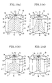
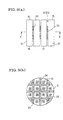
- Figs. 1(a), 1(b), 1(c) and 1(d) are each a perspective view showing an embodiment of the honeycomb structure according to the present invention.
- the honeycomb structures 10 shown in Figs. 1(a), 1(b), 1(c) and 1(d) are constituted by bonding four honeycomb segments 21 each having a large number of through-channels 11 extending in the axial direction (the gas flow direction) [an X direction in Figs. 1(a), 1(b), 1(c) and 1(d)] and separated from each other by partition walls.
- the honeycomb segments 21 are bonded to each other at their planes (bonded planes) 22 substantially parallel to the direction X of the through-channels 11 by a bonding material 25 composed of components substantially same as the components composing the honeycomb segments 21.
- Each bonded plane 22 has an unbonded area inclusive of an end portion 18 opening to the periphery 15 of the gas outlet side end face.
- the bonding material 25 is provided continuously.
- each unbonded area 12 is formed in a triangular shape so that the unbonded area 12 includes each part of the lengths of each bonded plane 22 opening to the gas outlet side end face 14 and side 13 of the honeycomb structure 10 and that the width of the unbonded area 12 in a direction Y from the side 13 of the honeycomb structure 10 toward its center becomes gradually smaller toward the gas inlet side end face 16 of the honeycomb structure 10.
- the honeycomb structure 10 shown in Fig. 10 shows that the honeycomb structure 10 includes each part of the lengths of each bonded plane 22 opening to the gas outlet side end face 14 and side 13 of the honeycomb structure 10 and that the width of the unbonded area 12 in a direction Y from the side 13 of the honeycomb structure 10 toward its center becomes gradually smaller toward the gas inlet side end face 16 of the honeycomb structure 10.
- each unbonded area 12 is formed in a rectangular shape so that the unbonded area 12 includes each part of the lengths of each bonded plane 22 opening to the gas outlet side end face 14 and side 13 of the honeycomb structure and that the width of the unbonded area 12 in a direction Y from the side 13 of the honeycomb structure 10 toward its center is constant toward the gas inlet side end face 16.
- each unbonded area 12 is formed in a triangular shape so that the unbonded area 12 includes the total length of each bonded plane 22 opening to the side 13 of the honeycomb structure 10 and part of the length of each bonded plane 22 contacting with the gas outlet side end face 14 of the honeycomb structure 10 and that the width of the unbonded area 12 in a direction Y from the side 13 of the honeycomb structure 10 toward its center becomes gradually smaller toward the gas inlet side end face 16 of the honeycomb structure 10.
- each unbonded area 12 is formed so that the unbonded area 12 includes the total length of the bonded plane 22 opening to the side 13 of the honeycomb structure 10 and each part of the lengths of each bonded plane 22 contacting with the gas outlet side end face 14 and gas inlet side end face 16 of the honeycomb structure 10 and that the width of the unbonded area 12 in a direction Y from the side 13 of the honeycomb structure 10 toward its center is equal thereto toward the gas outlet side end face.
- the individual portions of the honeycomb structure 10 can make free deformation without being restricted by each other, the thermal stress is reduced, and generation of cracks can be minimized.
- honeycomb structures 10 shown in Figs. 1(c) and 1(d) thermal stress is greatly reduced in the whole portion of honeycomb structure 10; therefore, these honeycomb structures are effective particularly in the application where temperature non-uniformity takes place in the whole portion of honeycomb structure 10.
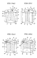
- honeycomb structures 10 shown in Figs. 2(a) and 2(b) are constituted by bonding three honeycomb segments 21.
- each unbonded area 12 is formed in a triangular shape so that the unbonded area 12 contains the total length of each bonded plane 22 contacting with the side 13 of the honeycomb structure 10 and part of the length of each bonded plane 22 opening to the gas outlet side end face 14 of the honeycomb structure 10 and that the width of the unbonded area 12 in a direction Y from the side 13 of the honeycomb structure 10 toward its center becomes gradually smaller toward the gas inlet side end face 16 of the honeycomb structure 10.
- the honeycomb structure 10 shown in Fig. 2(b) as in Fig.
- each unbonded area 12 is formed so that the unbonded area 12 includes the total length of the bonded plane 22 opening to the side 13 of the honeycomb structure 10 and each part of the lengths of each bonded plane 22 opening to the gas outlet side end face 14 and gas inlet side end face 16 of the honeycomb structure 10 and that the width of the unbonded area 12 in a direction Y from the side 13 of the honeycomb structure 10 toward its center is equal therero toward the gas inlet side end face 16.
- Figs. 3(a) and 3(b) are each a perspective view showing other embodiment of the honeycomb structure according to the present invention.
- each unbonded area 12 is formed so as to include part of the length of each bonded plane 22 contacting with the side 13 of the honeycomb structure 10 and the total length of the bonded plane 22 contacting with the gas outlet side end face 14 of the honeycomb structure 10. Further, in this structure, the unbonded areas 12 are formed so as to continuously connect the two points (A and B) and also the two points (C and D) of the periphery 15 of the gas outlet side end face and cross with each other at the center of the gas outlet side end face 14.
- each unbonded area 12 is formed so as to further include part of the length of the bonded plane 22 opening to the side 13 of the honeycomb structure 10 and the total length of the bonded plane 22 opening to the gas inlet side end face 16 of the honeycomb structure 10. Further, in this structure, the unbonded areas 12 are formed, as in the gas outlet side end face 14, so as to continuously connect the two points [not shown in Fig. 3(b)] of the periphery 17 of the gas inlet side end face and cross with each other at the center of the gas inlet side end face 16.
- a bonding material 25 is formed at the center of each honeycomb structure 10; and each unbonded area 12 is formed so as to include all of the lengths of each bonded plane 22 opening to the side 13, gas outlet side end face 14 and gas inlet side end face 16 of the honeycomb structure 10.
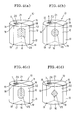
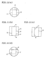
- Fig. 4(a) is a case wherein the bonding material 25 has a rectangular section;
- Fig. 4(b) is a case wherein the bonding material 25 has a circular section;
- Fig. 4(c) is a case wherein the bonding material 25 has a race truck-shaped section; and
- Fig. 4(d) is a case wherein the bonding material 25 has a rhombic section.
- each unbonded area 12 is formed so that the unbonded area 12 includes all of the lengths of each bonded plane 22 opening to the side 13 and gas outlet side end face 14 of the honeycomb structure 10 and part of the length of the bonded plane 22 opening to the gas inlet side end face 16 of the honeycomb structure 10 and that part of a bonding material 25 is exposed to the gas inlet side end face 16 of the honeycomb structure 10.
- each unbonded area 12 is formed so as to include all of the lengths of each bonded plane 22 opening to the side 13, gas outlet side end face 14 and gas inlet side end face 16 of each honeycomb structure 10. Further, these honeycomb structures are each constituted by bonding nine honeycomb segments 14 and therefore each have a large number of bonded planes 22.
- the bonding member 25 has a rectangular section; in the honeycomb structures 10 shown in Figs. 7(a) and 7(b), the bonding material 25 has an elliptical section.
- honeycomb structures 10 the same effect as mentioned for the honeycomb structures 10 shown in Figs. 4(a) to 4(d) is obtained; moreover, since a large number of unbonded areas 12 can be formed uniformly in each honeycomb structure 10, the thermal stress generating in the honeycomb structure 10 can be reduced greatly.
- honeycomb segments 21 are bonded by a bonding material 25; the bonding material 25 is provided at the center of each honeycomb structure 10; each unbonded area 12 is formed so as to include all of the lengths of each bonded plane 22 opening to the side 13, gas outlet side end face 14 and gas inlet side end face 16 of the honeycomb structure 10.
- each unbonded area 12 is provided in a portion of each unbonded area 12 so as to surround part of the bonding material 25 and be exposed to part of the side 13; and each unfilled portion 31 (which is a gap) is formed so as to contain part of the length of each bonded plane 22 contacting with the side 13 of the honeycomb structure 10 and all of the lengths of each bonded plane 22 opening to the gas outlet side end face 14 and gas inlet side end face 16 of the honeycomb structure 10.
- the honeycomb structure 10 shown in Figs. 9(a) and 9(b) has the same constitution as the honeycomb structure 10 shown in Figs. 8(a) and 8(b) except that as in the honeycomb structure 10 shown in Figs. 6(a) and 6(b), nine honeycomb segments 14 are bonded and therefore a large number of bonded planes 22 are formed.
- the same effect as mentioned for the honeycomb structure 10 shown in Figs. 8(a) and 8(b) is obtained; further, since a large number of unbonded areas 12 can be formed uniformly in the honeycomb structure 10, the thermal stress generating in the honeycomb structure 10 can be reduced to a very low level.
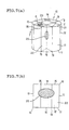
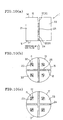
- Figs. 10(a), 10(b) and 10(c) show an embodiment used as a honeycomb filter.
- honeycomb filter segments 33 are bonded by a bonding material 25, the bonding material 25 is provided at the center of the honeycomb filter 1, and each unbonded area 12 is formed so as to include all of the lengths of each bonded plane 22 opening to the side 13, gas outlet side end face 14 and gas inlet side end face 16 of the honeycomb filter 1.
- a filler 24 is provided in a portion of each unbonded area 12 so as to block all the portion of the unbonded area 12 exposed to the gas inlet side end face 16 of the honeycomb filter 1; and an unfilled portion 31 which forms a gap without being filled with a filler is formed between the above filler 24 and the bonding material 25 and also so as to be exposed to the gas outlet side end face 14.
- This honeycomb filter 1 shows no accumulation of the soot present in exhaust gas, at the unfilled portion 31 of the gas inlet side of the filter 1 and can be suitably used as a honeycomb filter. Further, having no gap at the end face 14 of the gas outlet side or in the vicinity of the end face 16 of the gas inlet side, the honeycomb filter 1 shows a very large reduction in thermal stress.
- a mixed powder consisting of 75% by weight of a SiC powder and 25% by weight of a metal Si powder.
- methyl cellulose, hydroxypropyl methyl cellulose, a surfactant and water was added to produce a plastic kneaded material.
- this kneaded material was subjected to extrusion molding to obtain a cylindrical body.
- the cylindrical body was cut into nine parts in the axial direction at given intervals to obtain a plurality of honeycomb bodies of 0.3 mm in partition wall thickness and 31 cells/cm 2 in cell density, each having a different shape (e.g. fan or square) in a section perpendicular to the axial direction.
- honeycomb bodies were dried using a microwave and hot air, after which a bonding layer having the same composition as that of the above-mentioned kneaded material was formed on each honeycomb body at about the center of each plane of the honeycomb body parallel to the direction of the through-channels of the honeycomb body.
- the resulting honeycomb bodies were unified into one piece by bonding them via the bonding layer, followed by drying.
- the resulting unified material was subjected to debinding at about 400°C in an N 2 atmosphere and then fired at about 1,550°C in an inert gas atmosphere (e.g. Ar).
- a filler containing, for example, an aluminosilicate fiber, a SiC powder, a metal Si powder, an organic binder, an inorganic binder and water was filled at a width of 5 to 10 mm at part of the bonding layer-free area of each bonding layer-formed plane, followed by drying at about 100°C, whereby could be produced a honeycomb structure shown in Fig. 9, having a dimension of 144 mm (diameter) and 152 mm (length) and a gap (bonded area) of 2 mm.
- a honeycomb structure shown in Fig. 9 could be produced in the same manner as in Production Example 1 except that in Production Example 1, a plurality of rectangular parallelepiped honeycomb bodies of 50 mm x 50 mm (end face) were produced, unified into one piece, and fired to obtain a honeycomb structure, this honeycomb structure was subjected to machining of outer surface to obtain a cylinder of 144 mm (diameter) and 152 mm (length), a kneaded material (which was the same as the bonding layer formed previously) was coated on the side of the cylinder, and the kneaded material-coated cylinder was fired.
- a honeycomb structure shown in Fig. 9 could be produced in the same manner as in Production Example 1 except that in Production Example 1, a plurality of prismatic honeycomb bodies of 50 mm x 50 mm (end face) were produced, bonded into one piece, and fired to obtain a honeycomb structure, this honeycomb structure was subjected to machining of outer surface to obtain a cylinder of 144 mm (diameter) and 152 mm (length), a filler was coated on the side of the cylinder, and the filler-coated cylinder was dried.
- Honeycomb filters could be produced in the same manners as in Production Examples 1 to 3 except for the step of plugging alternately an every other end face of the inlet side and outlet side of the through-channels of the honeycomb segment.
- a SiC-made honeycomb body having a dimension of 144 mm (diameter) x 152 mm (length), a partition wall thickness of 0.3 mm and a cell density of 31 cells/cm 2 was produced according to Production Example 1; a plural number of through-channels of the honeycomb structure passing through the end face of the inlet side and the end face of the outlet side was alternately plugged every other end of the inlet side and outlet side of the honeycomb structure, whereby was produced a particulate honeycomb filter for purification of diesel engine exhaust gas.
- this honeycomb filter as shown in Fig.
- each unbonded area 12 was formed in a triangular shape so that the unbonded area 12 included each part of the lengths of each bonded plane 22 opening to the gas outlet side end face (upper end face) 14 and side 13 of the honeycomb structure 10 and that the width of the unbonded area 12 in a direction Y from the side 13 of the honeycomb structure 10 toward its center became gradually smaller toward the gas inlet side end face 16 of the honeycomb structure 10; and the lengths of each unbonded area 12 were 30 mm from the periphery 15 of the gas outlet side end face (upper end face) of the honeycomb structure 10 toward the direction of the channels of the through-channels and 50 mm from the periphery 15 of the gas outlet side end face (upper end face) of the honeycomb structure 10 toward its center.
- Honeycomb filters were produced in the same manner as in Example 1 except that they had structures having unbonded areas shown in Fig. 1(d), Fig. 3(a), Fig. 3(b), Fig. 4(a), Fig. 4(b) and Fig. 7 and that when each unbonded area 12 (gap) of honeycomb structure 10 was formed so as to be exposed to the gas inlet side end face (lower end face) 16, each exposed portion was filled with a filler 25 having the properties shown in Table 1, at a depth of 6 mm.
- Young s modulus ratio refers to a ratio of Young s modulus of filler to Young s modulus of honeycomb segment. Each Young s modulus was measured and calculated from the relation between load and displacement, according to a test method for isothermal elastic modulus.
- strength refers to a strength of filler to that of honeycomb segment. Each strength was measured using a material tester according to a four-point bending strength test (JIS 1601). A case when the filler had a larger strength, was reported as large ; and a case when the filler had a smaller strength, was reported as small .
- honeycomb filters same as that of Example 6 except that the fillers used had Young s moduli and strengths as shown in Table 1.
- each unbonded area 12 was formed so as to have a length of 15 mm from the periphery 15 of the gas outlet side end face (upper end face) of the honeycomb structure 10 toward its center and a length of 5 m from the periphery 15 of the gas outlet side end face (upper end face) of the honeycomb structure 10 toward the direction of the through-channels of the honeycomb structure 10.
- honeycomb filters same as that of Example 1 except that the structure shown in Fig. 3(a) was employed and that each unbonded area 12 was formed so as to have a length of 15 mm or 5 mm from the periphery 15 of the gas outlet side end face (upper end face) of the honeycomb structure 10 toward the direction of the through-channels of the honeycomb structure 10 and a length of 15 mm or 5 mm from the periphery 15 of the gas outlet side end face (upper end face) of the honeycomb structure 10 toward its center.
- a ceramic nonintumescent mat as a holding material was wound round the side 13 of a honeycomb structure (a honeycomb filter) 10 and forced into a canning case to obtain a canning structure. Then, a soot-containing combustion gas generated by burning a gas oil (a diesel fuel) was allowed to enter the honeycomb structure (honeycomb filter) 10 from its lower end face 16 and leave from its upper end face 14, to load soot in the honeycomb structure (honeycomb filter) 10. The honeycomb structure (honeycomb filter) 10 was allowed to cool to room temperature. Then, a combustion gas containing a given proportion of oxygen was allowed to enter the honeycomb structure (honeycomb filter) 10 from its lower end face 16, to burn and remove the soot. Thus, a filter regeneration test was conducted.
- a gas oil a diesel fuel
- the amount of soot loaded was set at six levels ranging from 10 g/liter to 20 g/liter (the transition period was standard), and the above-mentioned filter regeneration test was conducted.
- the individual portions are not restricted by each other and can make free deformation even when there appears temperature non-uniformity therein; therefore, thermal stress can be reduced and generation of cracks can be prevented.
Landscapes
- Chemical & Material Sciences (AREA)
- Engineering & Computer Science (AREA)
- Ceramic Engineering (AREA)
- Materials Engineering (AREA)
- Organic Chemistry (AREA)
- Structural Engineering (AREA)
- Manufacturing & Machinery (AREA)
- Chemical Kinetics & Catalysis (AREA)
- Mechanical Engineering (AREA)
- General Engineering & Computer Science (AREA)
- Combustion & Propulsion (AREA)
- Health & Medical Sciences (AREA)
- Toxicology (AREA)
- Inorganic Chemistry (AREA)
- Life Sciences & Earth Sciences (AREA)
- Geology (AREA)
- Filtering Materials (AREA)
- Ceramic Products (AREA)
- Catalysts (AREA)
- Exhaust Gas Treatment By Means Of Catalyst (AREA)
- Exhaust Gas After Treatment (AREA)
- Processes For Solid Components From Exhaust (AREA)
- Press-Shaping Or Shaping Using Conveyers (AREA)
Abstract
Description
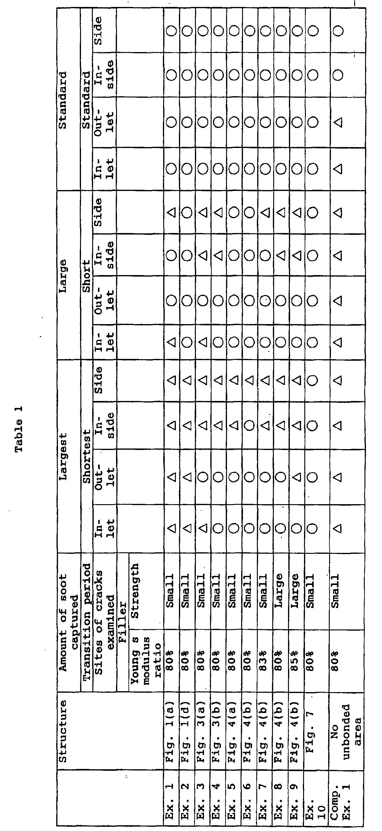

Claims (21)
characterized in that each bonded plane of each honeycomb segment includes an unbonded area inclusive of at least one edge portion opening to a periphery of its gas inlet side end face and/or a periphery of its gas outlet side end face.
characterized in that said honeycomb segments are composed mainly of metal Si and SiC and has a Si content defined by Si/(Si+SiC), of 5 to 50% by weight,
the bonding material is composed mainly of metal Si and SiC and its Si content defined by Si/(Si+SiC) is equal to or higher than Si content of said honeycomb segments and is 10 to 80% by weight, and that
each bonded plane of said honeycomb segments includes an unbonded area inclusive of at least one edge portion opening to a periphery of its gas inlet side end face and/or a periphery of its gas outlet side end face.
characterized in that the bonding material is provided continuously on each bonded plane.
characterized in that the unbonded area of each bonded plane is formed from the periphery of the gas inlet side end face or the periphery of the gas outlet side end face toward a direction of the through-channels, in a length of 10% or more relative to a total length of the honeycomb structure in said direction.
characterized in that the unbonded area of each bonded plane is formed from the periphery of the gas inlet side end face or the periphery of the gas outlet side end face toward a direction of a center of the end face, in a length of 10% or more relative to a total width of the end face of the honeycomb structure in said direction.
characterized in that a filler composed mainly of a heat-resistant inorganic material is provided on at least a part of the unbonded area of each bonded plane.
characterized in that the filler satisfies at least either one of requirements that its Young's modulus is 80% or less of the Young's modulus of honeycomb segments, and that its material strength is smaller than a material strength of said honeycomb segments.
characterized in that the honeycomb segments are composed mainly of at least one kind of ceramics selected from the group consisting of cordierite, mullite, alumina, spinel, silicon carbide, silicon nitride, lithium aluminum silicate, aluminum titanate and combinations thereof, or of a Fe-Cr-Al type metal.
characterized in that a catalyst is loaded on partition walls of the honeycomb segments.
characterized in that said honeycomb structure is a honeycomb filter.
characterized by
kneading powders of raw materials, a binder and water,
molding thus obtained kneaded material and drying a molded material to obtain a honeycomb body,
forming a bonding layer composed of components substantially same as components composing the honeycomb body, on each plane of honeycomb bodies substantially parallel to a direction of through-channels, at least exclusive of an edge portion opening to a periphery of its gas inlet side end face or a periphery of its gas outlet side end face,
bonding a plurality of resulting honeycomb bodies into unified honeycomb structures through said bonding layer, and
firing the resulting unified honeycomb structures.
Applications Claiming Priority (5)
| Application Number | Priority Date | Filing Date | Title |
|---|---|---|---|
| JP2000168234 | 2000-06-05 | ||
| JP2000168234 | 2000-06-05 | ||
| JP2001064077 | 2001-03-07 | ||
| JP2001064077A JP4511065B2 (en) | 2000-06-05 | 2001-03-07 | Honeycomb structure, honeycomb filter, and manufacturing method thereof |
| PCT/JP2001/004688 WO2001093984A1 (en) | 2000-06-05 | 2001-06-04 | Honeycomb structure and honeycomb filter, and method of producing them |
Publications (4)
| Publication Number | Publication Date |
|---|---|
| EP1291061A1 true EP1291061A1 (en) | 2003-03-12 |
| EP1291061A4 EP1291061A4 (en) | 2004-08-04 |
| EP1291061B1 EP1291061B1 (en) | 2008-05-14 |
| EP1291061B2 EP1291061B2 (en) | 2012-01-18 |
Family
ID=26593358
Family Applications (1)
| Application Number | Title | Priority Date | Filing Date |
|---|---|---|---|
| EP01936843A Expired - Lifetime EP1291061B2 (en) | 2000-06-05 | 2001-06-04 | Honeycomb structure and honeycomb filter, and method of producing them |
Country Status (6)
| Country | Link |
|---|---|
| US (1) | US7294316B2 (en) |
| EP (1) | EP1291061B2 (en) |
| JP (1) | JP4511065B2 (en) |
| AU (1) | AU6268801A (en) |
| DE (1) | DE60134016D1 (en) |
| WO (1) | WO2001093984A1 (en) |
Cited By (17)
| Publication number | Priority date | Publication date | Assignee | Title |
|---|---|---|---|---|
| WO2003099742A1 (en) | 2002-05-23 | 2003-12-04 | Ngk Insulators, Ltd. | Method for producing composite material |
| EP1283067A4 (en) * | 2001-03-16 | 2004-03-31 | Ngk Insulators Ltd | Honeycomb filter for purifying exhaust gas |
| EP1506948A4 (en) * | 2002-10-07 | 2006-04-26 | Ibiden Co Ltd | WOVEN STRUCTURE BODY |
| FR2878896A1 (en) * | 2004-12-07 | 2006-06-09 | Saint Gobain Ct Recherches | FILTRATION STRUCTURE, ESPECIALLY PARTICULATE FILTER FOR EXHAUST GASES OF AN INTERNAL COMBUSTION ENGINE, AND ASSOCIATED EXHAUST LINE |
| EP1698604A4 (en) * | 2003-11-12 | 2006-09-06 | Ibiden Co Ltd | BODY WITH A CERAMIC STRUCTURE, AND DEVICE AND METHOD FOR PRODUCING THE BODY WITH A CERAMIC STRUCTURE |
| EP1726800A1 (en) * | 2005-05-23 | 2006-11-29 | Ngk Insulators, Ltd. | Honeycomb structure |
| EP1736459A1 (en) * | 2005-06-24 | 2006-12-27 | Ibiden Co., Ltd. | Honeycomb structured body |
| EP1703095A4 (en) * | 2003-12-25 | 2007-02-28 | Ibiden Co Ltd | EXHAUST GAS PURIFICATION DEVICE AND METHOD FOR REGENERATING AN EXHAUST GAS PURIFYING DEVICE |
| EP1676622B1 (en) | 2003-10-23 | 2008-01-16 | Ibiden Co., Ltd. | Honeycomb structure body |
| US7531145B2 (en) | 2001-03-22 | 2009-05-12 | Ngk Insulators, Ltd. | Honeycomb structure |
| US7578864B2 (en) | 2003-07-14 | 2009-08-25 | Hitachi Metals, Ltd. | Ceramic honeycomb filter and its production method |
| US7713325B2 (en) | 2002-03-22 | 2010-05-11 | Ibiden Co., Ltd. | Method for manufacturing honeycomb filter for purifying exhaust gases |
| US7851041B2 (en) | 2005-06-24 | 2010-12-14 | Ibiden Co., Ltd. | Honeycomb structure |
| CN101945751A (en) * | 2007-12-20 | 2011-01-12 | 加州大学评议会 | Sintered porous structure and method of making same |
| US8071197B2 (en) | 2006-07-28 | 2011-12-06 | Fraunhofer-Gesellschaft Zur Foerderung Der Angewandten Forschung E.V. | Assembled honeycomb |
| EP2436663A1 (en) * | 2010-10-04 | 2012-04-04 | Ibiden Co., Ltd. | Method of manufacturing honeycomb structure |
| EP2712668A1 (en) * | 2012-09-28 | 2014-04-02 | NGK Insulators, Ltd. | Honeycomb filter |
Families Citing this family (61)
| Publication number | Priority date | Publication date | Assignee | Title |
|---|---|---|---|---|
| JP4404497B2 (en) * | 2001-03-01 | 2010-01-27 | 日本碍子株式会社 | Honeycomb filter and manufacturing method thereof |
| JP4511070B2 (en) | 2001-03-29 | 2010-07-28 | 日本碍子株式会社 | Honeycomb structure and assembly thereof |
| JP2003010616A (en) * | 2001-06-29 | 2003-01-14 | Ngk Insulators Ltd | Honeycomb structure |
| FR2833857B1 (en) * | 2001-12-20 | 2004-10-15 | Saint Gobain Ct Recherches | FILTER BODY COMPRISING A PLURALITY OF FILTER BLOCKS, IN PARTICULAR FOR A PARTICLE FILTER |
| JPWO2003067041A1 (en) * | 2002-02-05 | 2005-06-02 | イビデン株式会社 | Exhaust gas purification honeycomb filter, adhesive, coating material, and exhaust gas purification honeycomb filter manufacturing method |
| EP1479882B2 (en) | 2002-02-05 | 2012-08-22 | Ibiden Co., Ltd. | Honeycomb filter for exhaust gas decontamination |
| DE60321831D1 (en) * | 2002-03-15 | 2008-08-07 | Ibiden Co Ltd | Ceramic filter for emission control |
| DE60320966D1 (en) * | 2002-03-29 | 2008-06-26 | Ngk Insulators Ltd | SILICON CARBIDE-BASED POROUS MATERIAL AND METHOD OF MANUFACTURING THEREOF |
| US7090714B2 (en) | 2002-06-17 | 2006-08-15 | Hitachi Metals, Ltd. | Ceramic honeycomb filter |
| EP1550646A4 (en) * | 2002-10-07 | 2006-04-26 | Ibiden Co Ltd | STRUCTURAL BODY IN HONEYCOMB |
| JP4267947B2 (en) * | 2003-03-19 | 2009-05-27 | 日本碍子株式会社 | Honeycomb structure |
| KR101025849B1 (en) * | 2003-03-19 | 2011-03-30 | 엔지케이 인슐레이터 엘티디 | Honeycomb Structure |
| FR2853256B1 (en) * | 2003-04-01 | 2005-10-21 | Saint Gobain Ct Recherches | FILTRATION STRUCTURE, PARTICULARLY PARTICLE FILTER FOR THE EXHAUST GASES OF AN INTERNAL COMBUSTION ENGINE. |
| JP4408203B2 (en) * | 2003-05-12 | 2010-02-03 | 日本碍子株式会社 | Manufacturing method of honeycomb structure |
| FR2864577B1 (en) * | 2003-12-24 | 2006-05-05 | Saint Gobain Ct Recherches | FILTRATION STRUCTURE, ESPECIALLY PARTICULATE FILTER FOR EXHAUST GASES OF AN INTERNAL COMBUSTION ENGINE AND REINFORCING MEMBER FOR SUCH A STRUCTURE |
| FR2865661B1 (en) * | 2004-02-04 | 2006-05-05 | Saint Gobain Ct Recherches | FILTRATION STRUCTURE, PARTICULARLY PARTICLE FILTER FOR EXHAUST GASES OF AN INTERNAL COMBUSTION ENGINE, AND ASSOCIATED EXHAUST LINE |
| US20060228519A1 (en) * | 2004-03-05 | 2006-10-12 | Ngk Insulators, Ltd. | Honeycomb structure and method of producing the same |
| WO2005102963A1 (en) * | 2004-04-22 | 2005-11-03 | Ngk Insulators, Ltd. | Method for producing porous honeycomb structure and porous honeycomb structure |
| FR2874964B1 (en) * | 2004-09-06 | 2009-05-29 | Saint Gobain Ct Recherches | EXHAUST GAS FILTRATION STRUCTURE OF AN INTERNAL COMBUSTION ENGINE AND EXHAUST LINE THEREFOR |
| JP4822711B2 (en) * | 2005-01-17 | 2011-11-24 | 太平洋セメント株式会社 | Lightweight and highly rigid ceramic material and method for manufacturing the same |
| JP4753783B2 (en) * | 2005-06-24 | 2011-08-24 | イビデン株式会社 | Honeycomb structure |
| KR20080089473A (en) * | 2006-04-20 | 2008-10-06 | 이비덴 가부시키가이샤 | Honeycomb structure, manufacturing method of honeycomb structure, casing and exhaust gas purification device |
| US20070252310A1 (en) * | 2006-04-27 | 2007-11-01 | Brockway David J | Method for manufacturing a plugged honeycomb filter with a single firing cycle |
| DE102006043706A1 (en) | 2006-09-18 | 2008-03-27 | Robert Bosch Gmbh | Filter element, in particular for filtering exhaust gases of an internal combustion engine |
| EP2108430A4 (en) | 2007-02-02 | 2011-08-24 | Ngk Insulators Ltd | HONEYCOMB STRUCTURE |
| JP5498705B2 (en) * | 2007-02-02 | 2014-05-21 | 日本碍子株式会社 | Honeycomb structure |
| US8814974B2 (en) * | 2007-08-24 | 2014-08-26 | Corning Incorporated | Thin-walled porous ceramic wall-flow filter |
| JP2009190022A (en) * | 2007-11-21 | 2009-08-27 | Ibiden Co Ltd | Honeycomb structure and its manufacturing method |
| JP4990110B2 (en) | 2007-11-30 | 2012-08-01 | 株式会社日立製作所 | Engine system |
| WO2009118812A1 (en) * | 2008-03-24 | 2009-10-01 | イビデン株式会社 | Honeycomb structure |
| EP2113643B1 (en) * | 2008-03-24 | 2012-01-25 | Ibiden Co., Ltd. | Honeycomb structured body |
| WO2009141897A1 (en) * | 2008-05-20 | 2009-11-26 | イビデン株式会社 | Honeycomb structure |
| JP5667346B2 (en) * | 2009-03-17 | 2015-02-12 | 日本碍子株式会社 | Manufacturing method of honeycomb structure |
| JP5208836B2 (en) * | 2009-03-31 | 2013-06-12 | 日本碍子株式会社 | Manufacturing method of honeycomb structure |
| JP5280917B2 (en) * | 2009-03-31 | 2013-09-04 | 日本碍子株式会社 | Honeycomb structure |
| JP5137902B2 (en) * | 2009-06-08 | 2013-02-06 | 東京窯業株式会社 | Gas purification filter and method of manufacturing gas purification filter |
| JP5137900B2 (en) * | 2009-06-08 | 2013-02-06 | 東京窯業株式会社 | Manufacturing method of gas purification filter |
| JP2010281306A (en) * | 2009-06-08 | 2010-12-16 | Tokyo Yogyo Co Ltd | Gas purification filter |
| JP2010048256A (en) * | 2009-09-16 | 2010-03-04 | Ibiden Co Ltd | Method for manufacturing honeycomb filter and honeycomb filter |
| EP2616679A2 (en) | 2010-09-16 | 2013-07-24 | Wilson Solarpower Corporation | Concentrated solar power generation using solar receivers |
| US10041747B2 (en) * | 2010-09-22 | 2018-08-07 | Raytheon Company | Heat exchanger with a glass body |
| WO2012063341A1 (en) * | 2010-11-10 | 2012-05-18 | イビデン株式会社 | Method for producing honeycomb structure and device for degreasing honeycomb molded body |
| CN103339087B (en) * | 2011-02-04 | 2015-10-21 | 日本碍子株式会社 | Silicon carbide material, honeycomb structure and electrothermal catalyst carrier |
| EP2687502B1 (en) * | 2011-03-18 | 2019-06-12 | NGK Insulators, Ltd. | Silicon carbide-based porous object, honeycomb structure, and catalyst support of electric heating type |
| JP5811394B2 (en) * | 2011-07-21 | 2015-11-11 | トヨタ自動車株式会社 | Diesel particulate filter |
| CN118856636A (en) | 2012-03-21 | 2024-10-29 | 威尔逊太阳能公司 | Solar receivers, power generation systems, and heat storage and recovery systems |
| JP6022984B2 (en) * | 2013-03-29 | 2016-11-09 | 日本碍子株式会社 | Honeycomb structure and manufacturing method thereof |
| JP6111122B2 (en) * | 2013-03-29 | 2017-04-05 | 日本碍子株式会社 | Honeycomb structure and manufacturing method thereof |
| JP6022985B2 (en) * | 2013-03-29 | 2016-11-09 | 日本碍子株式会社 | Honeycomb structure |
| US9611163B2 (en) * | 2014-03-05 | 2017-04-04 | Owens-Brockway Glass Container Inc. | Process and apparatus for refining molten glass |
| JP6174511B2 (en) * | 2014-03-31 | 2017-08-02 | 日本碍子株式会社 | Honeycomb structure |
| JP6333632B2 (en) * | 2014-06-04 | 2018-05-30 | イビデン株式会社 | Manufacturing method of holding sealing material |
| KR101814459B1 (en) * | 2016-08-16 | 2018-01-04 | 희성촉매 주식회사 | A filter structure as a carrier for solid catalyst for producing an alkyl aromatic compound |
| JP6819178B2 (en) * | 2016-09-21 | 2021-01-27 | いすゞ自動車株式会社 | Particulate filter |
| JP7002377B2 (en) * | 2018-03-19 | 2022-01-20 | 日本碍子株式会社 | Honeycomb structure |
| JP7061491B2 (en) * | 2018-03-27 | 2022-04-28 | 日本碍子株式会社 | Honeycomb structure |
| JP7189824B2 (en) * | 2019-03-29 | 2022-12-14 | 日本碍子株式会社 | HONEYCOMB STRUCTURE AND METHOD FOR MANUFACTURING HONEYCOMB STRUCTURE |
| AU2021248410B2 (en) | 2020-04-02 | 2025-03-13 | 247Solar, Inc. | Concentrated solar energy collection, thermal storage, and power generation systems and methods with optional supplemental fuel production |
| CN116194186B (en) * | 2020-10-06 | 2026-03-31 | 安美世滤清系统公司 | Filter components with unique shapes |
| JP7594471B2 (en) * | 2021-03-16 | 2024-12-04 | 日本碍子株式会社 | Honeycomb structure and electrically heated carrier |
| WO2025187068A1 (en) * | 2024-03-08 | 2025-09-12 | 日本碍子株式会社 | Honeycomb structure |
Family Cites Families (13)
| Publication number | Priority date | Publication date | Assignee | Title |
|---|---|---|---|---|
| JPS5546338A (en) | 1978-09-28 | 1980-04-01 | Ngk Insulators Ltd | Heat and shock resistant, revolving and heat-regenerating type ceramic heat exchanger body and its manufacturing |
| US4335783A (en) * | 1980-11-10 | 1982-06-22 | Corning Glass Works | Method for improving thermal shock resistance of honeycombed structures formed from joined cellular segments |
| JP2505261B2 (en) * | 1988-09-29 | 1996-06-05 | 日本碍子株式会社 | Ceramic heat exchanger and manufacturing method thereof |
| JPH02117033A (en) | 1988-10-27 | 1990-05-01 | Meidensha Corp | Electrode material of vacuum interrupter |
| JPH0446816Y2 (en) * | 1989-03-10 | 1992-11-05 | ||
| JP2574472B2 (en) * | 1989-08-03 | 1997-01-22 | 松下電器産業株式会社 | Manufacturing method of honeycomb ceramics |
| JPH03121213A (en) | 1989-09-30 | 1991-05-23 | Ibiden Co Ltd | Honeycomb filter for exhaust gas purifying device |
| JPH04130069A (en) | 1990-09-19 | 1992-05-01 | Matsushita Electric Ind Co Ltd | Method for manufacturing honeycomb ceramic structure |
| US5449541A (en) † | 1992-10-27 | 1995-09-12 | Corning Incorporated | Electrically heatable honeycomb structures |
| US5914187A (en) | 1996-01-12 | 1999-06-22 | Ibiden Co., Ltd. | Ceramic structural body |
| US6939522B1 (en) * | 1999-11-19 | 2005-09-06 | Ngk Insulators, Ltd. | Honeycomb structure |
| JP4404497B2 (en) † | 2001-03-01 | 2010-01-27 | 日本碍子株式会社 | Honeycomb filter and manufacturing method thereof |
| JP4408183B2 (en) * | 2001-03-16 | 2010-02-03 | 日本碍子株式会社 | Honeycomb filter for exhaust gas purification |
-
2001
- 2001-03-07 JP JP2001064077A patent/JP4511065B2/en not_active Expired - Lifetime
- 2001-06-04 US US10/048,584 patent/US7294316B2/en not_active Expired - Lifetime
- 2001-06-04 AU AU62688/01A patent/AU6268801A/en not_active Abandoned
- 2001-06-04 WO PCT/JP2001/004688 patent/WO2001093984A1/en not_active Ceased
- 2001-06-04 DE DE60134016T patent/DE60134016D1/en not_active Expired - Lifetime
- 2001-06-04 EP EP01936843A patent/EP1291061B2/en not_active Expired - Lifetime
Cited By (34)
| Publication number | Priority date | Publication date | Assignee | Title |
|---|---|---|---|---|
| EP1283067A4 (en) * | 2001-03-16 | 2004-03-31 | Ngk Insulators Ltd | Honeycomb filter for purifying exhaust gas |
| US6942712B2 (en) | 2001-03-16 | 2005-09-13 | Ngk Insulators, Ltd. | Honeycomb filter for exhaust gas purification |
| US7531145B2 (en) | 2001-03-22 | 2009-05-12 | Ngk Insulators, Ltd. | Honeycomb structure |
| US7713325B2 (en) | 2002-03-22 | 2010-05-11 | Ibiden Co., Ltd. | Method for manufacturing honeycomb filter for purifying exhaust gases |
| EP1489277B2 (en) † | 2002-03-22 | 2012-08-22 | Ibiden Co., Ltd. | Method for manufacturing a honeycomb filter for purifying exhaust gases |
| WO2003099742A1 (en) | 2002-05-23 | 2003-12-04 | Ngk Insulators, Ltd. | Method for producing composite material |
| EP1506948A4 (en) * | 2002-10-07 | 2006-04-26 | Ibiden Co Ltd | WOVEN STRUCTURE BODY |
| US7387657B2 (en) | 2002-10-07 | 2008-06-17 | Ibiden Co., Ltd. | Honeycomb structural body |
| US7578864B2 (en) | 2003-07-14 | 2009-08-25 | Hitachi Metals, Ltd. | Ceramic honeycomb filter and its production method |
| EP1676622B1 (en) | 2003-10-23 | 2008-01-16 | Ibiden Co., Ltd. | Honeycomb structure body |
| EP1676622B2 (en) † | 2003-10-23 | 2020-04-22 | Ibiden Co., Ltd. | Honeycomb structure body |
| US7517502B2 (en) | 2003-10-23 | 2009-04-14 | Ibiden Co., Ltd. | Honeycomb structural body |
| EP1790623A1 (en) | 2003-11-12 | 2007-05-30 | Ibiden Co., Ltd. | Ceramic structure, device for manufacturing ceramic structure, and method of manufacturing ceramic structure |
| US7332014B2 (en) | 2003-11-12 | 2008-02-19 | Ibiden Co., Ltd. | Ceramic structure, method of manufacturing ceramic structure, and device for manufacturing ceramic structure |
| KR100779815B1 (en) * | 2003-11-12 | 2007-11-28 | 이비덴 가부시키가이샤 | Ceramic structure body |
| EP1698604A4 (en) * | 2003-11-12 | 2006-09-06 | Ibiden Co Ltd | BODY WITH A CERAMIC STRUCTURE, AND DEVICE AND METHOD FOR PRODUCING THE BODY WITH A CERAMIC STRUCTURE |
| EP1703095A4 (en) * | 2003-12-25 | 2007-02-28 | Ibiden Co Ltd | EXHAUST GAS PURIFICATION DEVICE AND METHOD FOR REGENERATING AN EXHAUST GAS PURIFYING DEVICE |
| WO2006061488A1 (en) * | 2004-12-07 | 2006-06-15 | Saint-Gobain Centre De Recherches Et D'etudes Europeen | Filtering structure, particularly a particle structure for the exhaust gases of an internal combustion engine and exhaust line associated therewith |
| RU2386042C2 (en) * | 2004-12-07 | 2010-04-10 | Сэн-Гобэн Сантр Де Решерш Э Д`Этюд Эропеэн | Filtering construction, namely filter-catcher of particles for cleaning exhaust gas of internal combustion engine, and outlet header connected to it |
| FR2878896A1 (en) * | 2004-12-07 | 2006-06-09 | Saint Gobain Ct Recherches | FILTRATION STRUCTURE, ESPECIALLY PARTICULATE FILTER FOR EXHAUST GASES OF AN INTERNAL COMBUSTION ENGINE, AND ASSOCIATED EXHAUST LINE |
| EP1726800A1 (en) * | 2005-05-23 | 2006-11-29 | Ngk Insulators, Ltd. | Honeycomb structure |
| US7531231B2 (en) | 2005-05-23 | 2009-05-12 | Ngk Insulators, Ltd. | Honeycomb structure |
| EP1726800B2 (en) † | 2005-05-23 | 2012-09-05 | NGK Insulators, Ltd. | Honeycomb structure |
| EP1736459A1 (en) * | 2005-06-24 | 2006-12-27 | Ibiden Co., Ltd. | Honeycomb structured body |
| US7892623B2 (en) | 2005-06-24 | 2011-02-22 | Ibiden Co., Ltd | Honeycomb structured body, manufacturing device of honeycomb structured body and manufacturing method of honeycomb structured body |
| US7851041B2 (en) | 2005-06-24 | 2010-12-14 | Ibiden Co., Ltd. | Honeycomb structure |
| CN100528342C (en) * | 2005-06-24 | 2009-08-19 | 揖斐电株式会社 | Honeycomb structure |
| US8071197B2 (en) | 2006-07-28 | 2011-12-06 | Fraunhofer-Gesellschaft Zur Foerderung Der Angewandten Forschung E.V. | Assembled honeycomb |
| EP2231384A4 (en) * | 2007-12-20 | 2011-01-19 | Univ California | SINTERED POROUS STRUCTURE AND METHOD FOR MANUFACTURING THE SAME |
| CN101945751A (en) * | 2007-12-20 | 2011-01-12 | 加州大学评议会 | Sintered porous structure and method of making same |
| EP2436663A1 (en) * | 2010-10-04 | 2012-04-04 | Ibiden Co., Ltd. | Method of manufacturing honeycomb structure |
| US8845952B2 (en) | 2010-10-04 | 2014-09-30 | Ibiden Co., Ltd. | Method of manufacturing honeycomb structure |
| EP2712668A1 (en) * | 2012-09-28 | 2014-04-02 | NGK Insulators, Ltd. | Honeycomb filter |
| US9212589B2 (en) | 2012-09-28 | 2015-12-15 | Ngk Insulators, Ltd. | Honeycomb filter |
Also Published As
| Publication number | Publication date |
|---|---|
| WO2001093984A1 (en) | 2001-12-13 |
| JP2002060279A (en) | 2002-02-26 |
| AU6268801A (en) | 2001-12-17 |
| EP1291061B1 (en) | 2008-05-14 |
| US20030053940A1 (en) | 2003-03-20 |
| DE60134016D1 (en) | 2008-06-26 |
| EP1291061A4 (en) | 2004-08-04 |
| JP4511065B2 (en) | 2010-07-28 |
| US7294316B2 (en) | 2007-11-13 |
| EP1291061B2 (en) | 2012-01-18 |
Similar Documents
| Publication | Publication Date | Title |
|---|---|---|
| US7294316B2 (en) | Honeycomb structure, honeycomb filter and processes for the production thereof | |
| EP1366792B1 (en) | Honeycomb filter and method for manufacturing the same | |
| EP1283067B1 (en) | Honeycomb filter for purifying exhaust gas | |
| EP1486243B1 (en) | Honeycomb filter | |
| EP1413345B1 (en) | Honeycomb structural body and method of manufacturing the structural body | |
| US6984253B2 (en) | Honeycomb filter | |
| US7169203B2 (en) | Honeycomb structure | |
| US7396576B2 (en) | Honeycomb structure | |
| EP2737945B1 (en) | Honeycomb Catalyst Body | |
| EP1983166A1 (en) | Honeycomb filter | |
| EP1413344A1 (en) | Honeycomb structural body | |
| US20040244344A1 (en) | Honeycomb filter | |
| EP2127719B1 (en) | Honeycomb structure | |
| US10857499B2 (en) | Plugged honeycomb structure | |
| US11027269B2 (en) | Plugged honeycomb structure | |
| US10765986B2 (en) | Plugged honeycomb structure | |
| JP2005144250A (en) | Honeycomb structure body | |
| JP4432024B2 (en) | Ceramic honeycomb structure | |
| ZA200200839B (en) | Honeycomb structure and honeycomb filter, and method of producing them. | |
| KR100607476B1 (en) | Honeycomb structure and method of manufacturing the same |
Legal Events
| Date | Code | Title | Description |
|---|---|---|---|
| PUAI | Public reference made under article 153(3) epc to a published international application that has entered the european phase |
Free format text: ORIGINAL CODE: 0009012 |
|
| 17P | Request for examination filed |
Effective date: 20020301 |
|
| AK | Designated contracting states |
Kind code of ref document: A1 Designated state(s): AT BE CH CY DE DK ES FI FR GB GR IE IT LI LU MC NL PT SE TR |
|
| AX | Request for extension of the european patent |
Extension state: AL LT LV MK RO SI |
|
| RBV | Designated contracting states (corrected) |
Designated state(s): BE DE FR |
|
| A4 | Supplementary search report drawn up and despatched |
Effective date: 20040622 |
|
| RIC1 | Information provided on ipc code assigned before grant |
Ipc: 7B 01J 35/04 A Ipc: 7C 04B 38/00 B |
|
| 17Q | First examination report despatched |
Effective date: 20041123 |
|
| GRAP | Despatch of communication of intention to grant a patent |
Free format text: ORIGINAL CODE: EPIDOSNIGR1 |
|
| GRAS | Grant fee paid |
Free format text: ORIGINAL CODE: EPIDOSNIGR3 |
|
| GRAA | (expected) grant |
Free format text: ORIGINAL CODE: 0009210 |
|
| AK | Designated contracting states |
Kind code of ref document: B1 Designated state(s): BE DE FR |
|
| REF | Corresponds to: |
Ref document number: 60134016 Country of ref document: DE Date of ref document: 20080626 Kind code of ref document: P |
|
| PLBI | Opposition filed |
Free format text: ORIGINAL CODE: 0009260 |
|
| PG25 | Lapsed in a contracting state [announced via postgrant information from national office to epo] |
Ref country code: BE Free format text: LAPSE BECAUSE OF FAILURE TO SUBMIT A TRANSLATION OF THE DESCRIPTION OR TO PAY THE FEE WITHIN THE PRESCRIBED TIME-LIMIT Effective date: 20080514 |
|
| PLAX | Notice of opposition and request to file observation + time limit sent |
Free format text: ORIGINAL CODE: EPIDOSNOBS2 |
|
| 26 | Opposition filed |
Opponent name: SAINT-GOBAIN CENTRE DE RECHERCHES ET D'ETUDES EURO Effective date: 20090211 |
|
| PLAF | Information modified related to communication of a notice of opposition and request to file observations + time limit |
Free format text: ORIGINAL CODE: EPIDOSCOBS2 |
|
| PLBB | Reply of patent proprietor to notice(s) of opposition received |
Free format text: ORIGINAL CODE: EPIDOSNOBS3 |
|
| APBM | Appeal reference recorded |
Free format text: ORIGINAL CODE: EPIDOSNREFNO |
|
| APBP | Date of receipt of notice of appeal recorded |
Free format text: ORIGINAL CODE: EPIDOSNNOA2O |
|
| APAH | Appeal reference modified |
Free format text: ORIGINAL CODE: EPIDOSCREFNO |
|
| APBU | Appeal procedure closed |
Free format text: ORIGINAL CODE: EPIDOSNNOA9O |
|
| PUAH | Patent maintained in amended form |
Free format text: ORIGINAL CODE: 0009272 |
|
| STAA | Information on the status of an ep patent application or granted ep patent |
Free format text: STATUS: PATENT MAINTAINED AS AMENDED |
|
| 27A | Patent maintained in amended form |
Effective date: 20120118 |
|
| AK | Designated contracting states |
Kind code of ref document: B2 Designated state(s): BE DE FR |
|
| REG | Reference to a national code |
Ref country code: DE Ref legal event code: R102 Ref document number: 60134016 Country of ref document: DE |
|
| REG | Reference to a national code |
Ref country code: DE Ref legal event code: R102 Ref document number: 60134016 Country of ref document: DE Effective date: 20120118 |
|
| REG | Reference to a national code |
Ref country code: FR Ref legal event code: PLFP Year of fee payment: 16 |
|
| REG | Reference to a national code |
Ref country code: FR Ref legal event code: PLFP Year of fee payment: 17 |
|
| REG | Reference to a national code |
Ref country code: FR Ref legal event code: PLFP Year of fee payment: 18 |
|
| PGFP | Annual fee paid to national office [announced via postgrant information from national office to epo] |
Ref country code: DE Payment date: 20200519 Year of fee payment: 20 Ref country code: FR Payment date: 20200512 Year of fee payment: 20 |
|
| REG | Reference to a national code |
Ref country code: DE Ref legal event code: R071 Ref document number: 60134016 Country of ref document: DE |