EP1290975A1 - Pulsimeter - Google Patents
Pulsimeter Download PDFInfo
- Publication number
- EP1290975A1 EP1290975A1 EP02256112A EP02256112A EP1290975A1 EP 1290975 A1 EP1290975 A1 EP 1290975A1 EP 02256112 A EP02256112 A EP 02256112A EP 02256112 A EP02256112 A EP 02256112A EP 1290975 A1 EP1290975 A1 EP 1290975A1
- Authority
- EP
- European Patent Office
- Prior art keywords
- contact
- pulse sensor
- pulse
- skin
- pulsimeter
- Prior art date
- Legal status (The legal status is an assumption and is not a legal conclusion. Google has not performed a legal analysis and makes no representation as to the accuracy of the status listed.)
- Withdrawn
Links
Images


Classifications
-
- G—PHYSICS
- G04—HOROLOGY
- G04G—ELECTRONIC TIME-PIECES
- G04G21/00—Input or output devices integrated in time-pieces
- G04G21/02—Detectors of external physical values, e.g. temperature
- G04G21/025—Detectors of external physical values, e.g. temperature for measuring physiological data
-
- A—HUMAN NECESSITIES
- A61—MEDICAL OR VETERINARY SCIENCE; HYGIENE
- A61B—DIAGNOSIS; SURGERY; IDENTIFICATION
- A61B5/00—Measuring for diagnostic purposes; Identification of persons
- A61B5/02—Detecting, measuring or recording for evaluating the cardiovascular system, e.g. pulse, heart rate, blood pressure or blood flow
- A61B5/024—Measuring pulse rate or heart rate
- A61B5/02438—Measuring pulse rate or heart rate with portable devices, e.g. worn by the patient
-
- A—HUMAN NECESSITIES
- A61—MEDICAL OR VETERINARY SCIENCE; HYGIENE
- A61B—DIAGNOSIS; SURGERY; IDENTIFICATION
- A61B5/00—Measuring for diagnostic purposes; Identification of persons
- A61B5/68—Arrangements of detecting, measuring or recording means, e.g. sensors, in relation to patient
- A61B5/6801—Arrangements of detecting, measuring or recording means, e.g. sensors, in relation to patient specially adapted to be attached to or worn on the body surface
- A61B5/6802—Sensor mounted on worn items
- A61B5/681—Wristwatch-type devices
-
- A—HUMAN NECESSITIES
- A61—MEDICAL OR VETERINARY SCIENCE; HYGIENE
- A61B—DIAGNOSIS; SURGERY; IDENTIFICATION
- A61B5/00—Measuring for diagnostic purposes; Identification of persons
- A61B5/02—Detecting, measuring or recording for evaluating the cardiovascular system, e.g. pulse, heart rate, blood pressure or blood flow
-
- A—HUMAN NECESSITIES
- A61—MEDICAL OR VETERINARY SCIENCE; HYGIENE
- A61B—DIAGNOSIS; SURGERY; IDENTIFICATION
- A61B5/00—Measuring for diagnostic purposes; Identification of persons
- A61B5/02—Detecting, measuring or recording for evaluating the cardiovascular system, e.g. pulse, heart rate, blood pressure or blood flow
- A61B5/024—Measuring pulse rate or heart rate
- A61B5/02416—Measuring pulse rate or heart rate using photoplethysmograph signals, e.g. generated by infrared radiation
Definitions
- the present invention relates to a portable pulsimeter to be equipped in, for example, a wristwatch or the like, and more specifically to a pulsimeter which does not measure a pulse rate when a pulse sensor is not brought into contact with a skin.
- a portable pulsimeter capable of measuring a pulse rate while attached to an arm or the like, for example, a wristwatch equipped with a pulsimeter (for example, see Japanese Patent Application Laid-open No. Hei 10-258040) is devised.
- a portable pulsimeter light or ultrasound is irradiated to a blood vessel, a reflected signal from the blood vessel is received using a pulse sensor including an optical sensor, and a pulse signal corresponding to a pulse is extracted from the reflected signal to obtain a pulse rate.
- the pulse sensor when it goes into a pulse rate measurement mode by an input instruction from a user, the pulse sensor is driven by a driver circuit to perform a pulse detection operation regardless of whether or not the pulse sensor is attached to the arm or the like of the user.
- an internal microcomputer judges insufficient sensitivity of a receiving signal and increases an amplification factor of an amplifying circuit for amplifying an output signal from the pulse sensor in order to improve the sensitivity.
- the microcomputer increases stepwise the amplification factor of an amplifying circuit while the insufficient sensitivity is judged and the amplification factor finally reaches the maximum. After that, the pulse sensor continues the pulse detection operation at the maximum amplification factor.
- the pulse sensor is a type for irradiating light or ultrasound to a skin and detecting a pulse signal, since the power consumption for irradiating light or ultrasound is relatively large, this problem becomes particularly remarkable.
- the present invention has been made in view of the above problems, and an object of the present invention is therefore to provide a pulsimeter capable of stopping pulse rate measurement processing of the pulsimeter when the pulse sensor is not in contact with a skin.
- a pulsimeter of the present invention is characterized by including drive means for driving a pulse sensor, contact detection means for detecting whether or not the pulse sensor is in contact with a skin, and control means for stopping drive of the pulse sensor by the drive means when the contact detection means detects that the pulse sensor is not in contact with the skin.
- the contact detection means detects whether or not the pulse sensor is in contact with the skin.
- the control means stops the drive of the pulse sensor by the drive means.
- the contact with the skin includes not only the case of a direct contact with the skin but also a state in which there is a somewhat distance from the skin but it is considered that the sensor is substantially attached thereto.
- the utilization efficiency of the battery of the pulsimeter can be improved.
- the above structure may further include display means for displaying pulse data measured by the pulse sensor.
- the display means may display a message that the pulse sensor is not in contact with the skin.
- signal detection judging means for judging whether or not a pulse signal from the pulse sensor is detected may be further included. Even in the case where the contact detection means detects that the pulse sensor is in contact with the skin, when it is judged by the signal detection judging means that the pulse signal from the pulse sensor is not detected, the display means may be constructed so as to display a message that an attachment position of the pulse sensor is unsuitable. According to the present invention, since it is constructed so as to further include such display means, the convenience of a user can be improved.
- the contact detection means may be constructed so as to include two electrodes protruding from the rear side of a cabinet with the pulse sensor and to detect whether or not the pulse sensor is in contact with the skin by a potential difference between the electrodes.
- the two electrodes of the contact detection means each protrude in a surrounding shape of the pulse sensor and it may be constructed such that the two electrodes are provided to be opposite to each other at a skin contact side of the cabinet.
- the surrounding shape includes a substantially semicircle or a substantially semisquare.
- the contact detection means may be constructed so as to judge whether or not the pulse sensor is in contact with the skin based on a predetermined time.
- the pulse rate can be efficiently measured.
- any one of the above structures it may be constructed as a pulsimeter in which the pulse sensor transmits and receives ultrasound.
- a pulsimeter of the present invention is characterized by including a driver to drive a pulse sensor, a contact detector to detect whether or not the pulse sensor is in contact with a skin, and a controller to stop drive of the pulse sensor by the driver when the contact detector detects that the pulse sensor is not in contact with the skin.
- the display may display a message that the pulse sensor is not in contact with the skin.
- a signal detection judging circuit to judge whether or not a pulse signal from the pulse sensor is detected, wherein even in the case where the contact detector detects that the pulse sensor is in contact with the skin, when it is judged by the signal detection judging circuit that the pulse signal from the pulse sensor is not detected, the display displays a message that an attachment position of the pulse sensor is unsuitable.
- Fig. 1 is a schematic block diagram indicating a circuit structure of a pulsimeter 1 according to an embodiment mode to which the present invention is applied.
- the pulsimeter 1 includes a CPU (central processing unit) 11, a contact detection circuit 12, a drive circuit 13, a transmitting circuit 14, a sensor circuit 15, an amplifying circuit 16, an A/D converting circuit 17, an input circuit 18, a display drive circuit 19, a display unit 20, a ROM (read only memory) 21, an EEPROM (electrically erasable programmable read only memory) 22, a RAM (random access memory) 23, an oscillating circuit 24, and a frequency dividing circuit 25.
- the respective elements except for the transmitting circuit 14, the sensor circuit 15, the amplifying circuit 16, and the display unit 20 are connected with the CPU 11 through buses.
- the CPU 11 executes pulse signal detection processing and pulse rate measurement processing, which are described later, and these processing programs are stored in the ROM 21.
- the input circuit 18 includes an input button which can be pushed down by a user.
- the RAM 23 expands the corresponding processing program stored in the ROM 21 at the execution of the above processing and temporally stores outputs based on the processing (for example, measurement results of the pulse rate and data indicating no contact).
- the CPU 11 causes the display unit 20 to display the outputs by the processing, which is temporally stored in the RAM 23, through the display drive circuit 19.
- the display unit 20 may be a liquid crystal display unit capable of performing digital display, which is located in a dial of the wristwatch.
- the contact detection circuit 12 is a circuit for detecting whether or not the pulsimeter 1 is in contact with the skin of the user in the pulse signal detection processing and includes two electrodes A and B as shown in Fig. 2.
- the drive circuit 13 drives or stops the transmitting circuit 14 by an instruction from the CPU 11.
- the transmitting circuit 14 includes a transmitter such as a light emitting diode for irradiating light to a blood vessel under the skin of the user.
- the transmitter may be a one for outputting ultrasound.
- the sensor circuit 15 includes a receiver such as a photodiode for detecting light or ultrasound which is irradiated from the transmitting circuit 14 and reflected from the blood vessel as a reflected signal and outputs the reflected signal to the amplifying circuit 16.
- the amplifying circuit 16 amplifies an input signal inputted from the sensor circuit 15 at a predetermined amplification instructed by the CPU 11 and outputs it to the A/D converting circuit 17.
- the A/D converting circuit 17 A/D-converts the input signal and outputs digital data to the RAM 23 through the CPU 11.
- Figs. 2 schematically show pulse sensor module structures of the pulsimeter 1 of the present invention
- 2A is a side view
- 2B is a rear view
- 2C shows a modified example of a rear surface.
- the electrodes A and B included in the contact detection circuit 12 one becomes a ground (earth) of this circuit and the other is connected with the input circuit pulled up by a high resistor.
- Fig. 3 shows one example of electrode connection.
- Fig. 3 shows a circuit structure of the two electrodes of the contact detection circuit 12 of the present invention.
- a resistor having a high resistance of 18 M ⁇ is used here.
- a voltage between both the electrodes is decreased by discharge through the skin.
- the CPU 11 judges that the pulse sensor is in contact with the skin.
- the transmitter and the receiver of the pulse sensor are shown in Figs. 2.
- a light emitting diode can be used as the transmitter and a photodiode can be used as the receiver.
- a pulse signal corresponding to a pulse is detected from the received light to measure a pulse rate.
- it is utilized in the case of an ultrasound irradiation type that a pulse is a flowing blood flux. That is, the Doppler effect of the reflected signal produced when a blood vessel expands and contracts by a flowing blood is utilized and a change in a frequency of ultrasound is detected to measure a pulse rate.
- Fig. 2C Another embodiment mode of the present invention is indicated in Fig. 2C as a modified example of the arrangement of the respective elements shown in Fig. 2B.
- the pulsimeter 1 is constructed such that two electrodes protruding in a circumference shape of a semicircle are located to be opposite to each other and the transmitter and the receiver are provided inside the circumference.
- the transmitter and the receiver are surrounded by the two electrodes, it can be prevented that the receiver is influenced by the disturbance of an external light at a pulse rate measurement, that is, light shielding can be conducted.
- the shape of the two electrodes is not limited to the above example.
- the two electrodes are preferably ones which are capable of preventing the influence of the disturbance of an external light on the receiver and have a shape and a size such that they are fit on the rear surface of the cabinet.
- these electrodes are preferably located at the outer side than at least the transmitter and the receiver.
- Fig. 4 is a flowchart of the pulse signal detection processing according to one embodiment mode to which the present invention is applied.
- the pulse signal detection processing is started in accordance with an input instruction (corresponding to interruption of 128 Hz in the pulse rate measurement processing) from the input circuit 18 by a user.
- Vw is not Low
- the processing is transferred to step S4 and the CPU 11 judges whether or not this state is continued for 1 second or longer.
- the CPU 11 judges that the pulse sensor is not in contact with the skin.
- the state is continued for 1 second or shorter, the state where the sensor is instantaneously floated is judged.
- a duration for contact detection is preferably set to be in a range in which there is not a problem such that a user is kept waiting long enough to feel discomfort at usage, and so forth. It may be set not only 1 second but also 2 to 3 seconds.
- step S7 CPU 11 judges whether or not an output voltage Vsen of the sensor circuit 15 is smaller than 10 mV.
- the CPU 11 judges whether or not an amplification factor of the amplifying circuit 16 is the maximum in step S8.
- the amplification factor is not the maximum, it is upped (step S9) and the processing is transferred to step S11.
- the CPU 11 drives the display drive circuit 19 to display a message "poor attachment" on the display unit 20 (step S10) and causes the pulse sensor to be in an OFF state by the drive circuit 13 (step S15) and the pulse signal detection processing is completed.
- step S7 when it is judged in step S7 that Vsen is not smaller than 10 mV, the CPU 11 judges whether or not Vsen is larger than 2 V in step S11. When it is judged that Vsen is larger than 2 V, the CPU 11 judges whether or not the amplification factor of the amplifying circuit 16 is the minimum in step S12. When the amplification factor is not the minimum, it is downed (step S13) and the pulse signal detection processing is completed. On the other hand, when the amplification factor is the minimum, the CPU 11 drives the display drive circuit 19 to display a message "range over" on the display unit 20 (step S14) and causes the pulse sensor to be in an OFF state by the drive circuit 13 (step S15) and the pulse signal detection processing is completed. On the other hand, when it is judged that Vsen is not larger than 2 V, the pulse signal detection processing is completed without any processing.
- one stage loop is formed with respect to the up and down of the amplification factor of the amplifying circuit 16.
- multistage control is required.
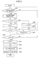
- Fig. 5 is a flowchart of pulse rate measurement processing according to one embodiment mode to which the present invention is applied.
- the CPU judges whether or not an interruption of 128 Hz is produced and waits in step S16 until the interruption is produced.
- the CPU 11 causes the RAM 23 to expand the corresponding program stored in the ROM 21 and executes the above pulse signal detection processing (step S17). Then, the processing is transferred to step S18.
- step the CPU 11 judges whether or not f1_off stored in the RAM 23 is 1.
- f1_off is not 1
- FFT first Fourier transform
- the pulsimeter 1 is constructed by including the drive circuit 13 for driving the transmitting circuit 14, the contact detection circuit 12 for detecting whether or not the pulse sensor is in contact with the skin, the CPU 11 for controlling these circuits, and the ROM 21 for storing the respective processing programs.
- the CPU 11 stops the drive of the pulse sensor by the drive circuit 13.
- the CPU judges whether or not the pulse sensor is poorly attached in accordance with the amplification factor of the amplifying circuit 16 and stops the drive of the pulse sensor by the driver circuit 13 based on the judgement.
- the utilization efficiency of the battery of a pulsimeter can be improved by using the plusimeter 1.
- the pulsimeter of the present invention when the pulse sensor is not in contact with the skin or when it is poorly attached, since the drive of the sensor can be stopped, the utilization efficiency of the battery of the pulsimeter can be improved.
Landscapes
- Health & Medical Sciences (AREA)
- Life Sciences & Earth Sciences (AREA)
- Physics & Mathematics (AREA)
- Biophysics (AREA)
- General Health & Medical Sciences (AREA)
- Biomedical Technology (AREA)
- Medical Informatics (AREA)
- Cardiology (AREA)
- Pathology (AREA)
- Engineering & Computer Science (AREA)
- Physiology (AREA)
- Heart & Thoracic Surgery (AREA)
- Veterinary Medicine (AREA)
- Molecular Biology (AREA)
- Surgery (AREA)
- Animal Behavior & Ethology (AREA)
- Public Health (AREA)
- General Physics & Mathematics (AREA)
- Measuring Pulse, Heart Rate, Blood Pressure Or Blood Flow (AREA)
- Ultra Sonic Daignosis Equipment (AREA)
Abstract
Description
- Field of the Invention: The present invention relates to a portable pulsimeter to be equipped in, for example, a wristwatch or the like, and more specifically to a pulsimeter which does not measure a pulse rate when a pulse sensor is not brought into contact with a skin.
- With growing interest in health care, a portable pulsimeter capable of measuring a pulse rate while attached to an arm or the like, for example, a wristwatch equipped with a pulsimeter (for example, see Japanese Patent Application Laid-open No. Hei 10-258040) is devised. According to such a portable pulsimeter, light or ultrasound is irradiated to a blood vessel, a reflected signal from the blood vessel is received using a pulse sensor including an optical sensor, and a pulse signal corresponding to a pulse is extracted from the reflected signal to obtain a pulse rate.
- According to a conventional wristwatch equipped with a pulsimeter, when it goes into a pulse rate measurement mode by an input instruction from a user, the pulse sensor is driven by a driver circuit to perform a pulse detection operation regardless of whether or not the pulse sensor is attached to the arm or the like of the user.
- Here, when the pulse sensor is not attached to the arm or the like of the user, since the reflected signal from the blood vessel becomes small, an internal microcomputer (for example, a CPU or the like) judges insufficient sensitivity of a receiving signal and increases an amplification factor of an amplifying circuit for amplifying an output signal from the pulse sensor in order to improve the sensitivity. Thus, the microcomputer increases stepwise the amplification factor of an amplifying circuit while the insufficient sensitivity is judged and the amplification factor finally reaches the maximum. After that, the pulse sensor continues the pulse detection operation at the maximum amplification factor.
- However, according to such a conventional wristwatch equipped with a pulsimeter, when the pulse sensor is detached while the pulse rate measurement mode is set by a user, or when the pulse rate measurement mode is set by a user while the pulse sensor is detached, there is a problem in that an unnecessary pulse detection operation is performed and the utilization efficiency of a battery is reduced.
- When the pulse sensor is a type for irradiating light or ultrasound to a skin and detecting a pulse signal, since the power consumption for irradiating light or ultrasound is relatively large, this problem becomes particularly remarkable.
- Thus, this becomes a problem even in the wristwatch equipped with the pulsimeter. In addition, when it is a specific device for measuring a pulse rate and the detection operation is performed with a state in which the pulse sensor is not attached or is poorly attached, a reduction in utilization efficiency of a battery further becomes a problem.
- The present invention has been made in view of the above problems, and an object of the present invention is therefore to provide a pulsimeter capable of stopping pulse rate measurement processing of the pulsimeter when the pulse sensor is not in contact with a skin.
- In order to solve the above problems, a pulsimeter of the present invention is characterized by including drive means for driving a pulse sensor, contact detection means for detecting whether or not the pulse sensor is in contact with a skin, and control means for stopping drive of the pulse sensor by the drive means when the contact detection means detects that the pulse sensor is not in contact with the skin.
- According to the present invention, the contact detection means detects whether or not the pulse sensor is in contact with the skin. When it detects that the pulse sensor is not in contact with the skin, the control means stops the drive of the pulse sensor by the drive means. Here, the contact with the skin includes not only the case of a direct contact with the skin but also a state in which there is a somewhat distance from the skin but it is considered that the sensor is substantially attached thereto.
- Therefore, according to the present invention, when the pulse sensor is not in contact with the skin, since the drive of the sensor is stopped, the utilization efficiency of the battery of the pulsimeter can be improved.
- Also, according to the present invention, the above structure may further include display means for displaying pulse data measured by the pulse sensor. When the contact detection means detects that the pulse sensor is not in contact with the skin, the display means may display a message that the pulse sensor is not in contact with the skin.
- Further, according to the present invention, signal detection judging means for judging whether or not a pulse signal from the pulse sensor is detected may be further included. Even in the case where the contact detection means detects that the pulse sensor is in contact with the skin, when it is judged by the signal detection judging means that the pulse signal from the pulse sensor is not detected, the display means may be constructed so as to display a message that an attachment position of the pulse sensor is unsuitable. According to the present invention, since it is constructed so as to further include such display means, the convenience of a user can be improved.
- Also, according to the present invention, the contact detection means may be constructed so as to include two electrodes protruding from the rear side of a cabinet with the pulse sensor and to detect whether or not the pulse sensor is in contact with the skin by a potential difference between the electrodes. The two electrodes of the contact detection means each protrude in a surrounding shape of the pulse sensor and it may be constructed such that the two electrodes are provided to be opposite to each other at a skin contact side of the cabinet. The surrounding shape includes a substantially semicircle or a substantially semisquare.
- Further, according to the present invention, the contact detection means may be constructed so as to judge whether or not the pulse sensor is in contact with the skin based on a predetermined time. Thus, when it is judged based on the predetermined time, since there is no case where the drive of the pulse sensor is stopped by instant poor contact or the like, the pulse rate can be efficiently measured.
- Also, according to the present invention, in any one of the above structures, it may be constructed as a pulsimeter in which the pulse sensor transmits and receives ultrasound.
- A pulsimeter of the present invention is characterized by including a driver to drive a pulse sensor, a contact detector to detect whether or not the pulse sensor is in contact with a skin, and a controller to stop drive of the pulse sensor by the driver when the contact detector detects that the pulse sensor is not in contact with the skin.
- Also, according to the present invention, further comprising a display to display pulse data measured by the pulse sensor.
- Also, according to the present invention, wherein when the contact detector detects that the pulse sensor is not in contact with the skin, the display may display a message that the pulse sensor is not in contact with the skin.
- Also, according to the present invention, further comprising a signal detection judging circuit to judge whether or not a pulse signal from the pulse sensor is detected, wherein even in the case where the contact detector detects that the pulse sensor is in contact with the skin, when it is judged by the signal detection judging circuit that the pulse signal from the pulse sensor is not detected, the display displays a message that an attachment position of the pulse sensor is unsuitable.
- Embodiments of the present invention will now be described by way of further example only and with reference to the accompanying drawings, in which:-
- Fig. 1 is a schematic block diagram showing a circuit structure of a pulsimeter according to one embodiment mode to which the present invention is applied;
- Figs. 2 are concept views of pulse sensor module structures of the pulsimeter according to one embodiment mode to which the present invention is applied, in which 2A is a side view, 2B is a rear view, and 2C shows a modified example of an arrangement of respective elements in a rear surface;
- Fig. 3 is a schematic diagram showing a circuit structure of a contact detection circuit according to one embodiment mode to which the present invention is applied;
- Fig. 4 is a flowchart of pulse signal detection processing executed by a CPU according to one embodiment mode to which the present invention is applied; and
- Fig. 5 is a flowchart of pulse rate measurement processing executed by a CPU according to one embodiment mode to which the present invention is applied.
-
- Hereinafter, an embodiment mode of a pulsimeter according to the present invention will be described in detail with reference to Figs. 1 to 5. Note that the embodiment mode is indicated as an example and the present invention should not be restrictively interpreted by this.
- Fig. 1 is a schematic block diagram indicating a circuit structure of a
pulsimeter 1 according to an embodiment mode to which the present invention is applied. Thepulsimeter 1 includes a CPU (central processing unit) 11, acontact detection circuit 12, adrive circuit 13, atransmitting circuit 14, asensor circuit 15, anamplifying circuit 16, an A/D converting circuit 17, aninput circuit 18, adisplay drive circuit 19, adisplay unit 20, a ROM (read only memory) 21, an EEPROM (electrically erasable programmable read only memory) 22, a RAM (random access memory) 23, anoscillating circuit 24, and afrequency dividing circuit 25. The respective elements except for thetransmitting circuit 14, thesensor circuit 15, the amplifyingcircuit 16, and thedisplay unit 20 are connected with theCPU 11 through buses. - The
CPU 11 executes pulse signal detection processing and pulse rate measurement processing, which are described later, and these processing programs are stored in theROM 21. Theinput circuit 18 includes an input button which can be pushed down by a user. TheRAM 23 expands the corresponding processing program stored in theROM 21 at the execution of the above processing and temporally stores outputs based on the processing (for example, measurement results of the pulse rate and data indicating no contact). - Also, the
CPU 11 causes thedisplay unit 20 to display the outputs by the processing, which is temporally stored in theRAM 23, through thedisplay drive circuit 19. Note that, when thepulsimeter 1 is a wristwatch equipped with a pulsimeter, thedisplay unit 20 may be a liquid crystal display unit capable of performing digital display, which is located in a dial of the wristwatch. - The
contact detection circuit 12 is a circuit for detecting whether or not thepulsimeter 1 is in contact with the skin of the user in the pulse signal detection processing and includes two electrodes A and B as shown in Fig. 2. Thedrive circuit 13 drives or stops the transmittingcircuit 14 by an instruction from theCPU 11. The transmittingcircuit 14 includes a transmitter such as a light emitting diode for irradiating light to a blood vessel under the skin of the user. The transmitter may be a one for outputting ultrasound. - The
sensor circuit 15 includes a receiver such as a photodiode for detecting light or ultrasound which is irradiated from the transmittingcircuit 14 and reflected from the blood vessel as a reflected signal and outputs the reflected signal to the amplifyingcircuit 16. The amplifyingcircuit 16 amplifies an input signal inputted from thesensor circuit 15 at a predetermined amplification instructed by theCPU 11 and outputs it to the A/D converting circuit 17. In addition, the A/D converting circuit 17 A/D-converts the input signal and outputs digital data to theRAM 23 through theCPU 11. - Figs. 2 schematically show pulse sensor module structures of the
pulsimeter 1 of the present invention, 2A is a side view, 2B is a rear view, and 2C shows a modified example of a rear surface. In these drawings, with respect to the electrodes A and B included in thecontact detection circuit 12, one becomes a ground (earth) of this circuit and the other is connected with the input circuit pulled up by a high resistor. Fig. 3 shows one example of electrode connection. - Fig. 3 shows a circuit structure of the two electrodes of the
contact detection circuit 12 of the present invention. A resistor having a high resistance of 18 MΩ is used here. When both the two electrodes are in contact with the skin, a voltage between both the electrodes is decreased by discharge through the skin. When it is detected through a gate that the voltage is low (Low), theCPU 11 judges that the pulse sensor is in contact with the skin. - Also, the transmitter and the receiver of the pulse sensor are shown in Figs. 2. When light is irradiated to the skin, for example, a light emitting diode can be used as the transmitter and a photodiode can be used as the receiver. A pulse signal corresponding to a pulse is detected from the received light to measure a pulse rate. In contrast to this, it is utilized in the case of an ultrasound irradiation type that a pulse is a flowing blood flux. That is, the Doppler effect of the reflected signal produced when a blood vessel expands and contracts by a flowing blood is utilized and a change in a frequency of ultrasound is detected to measure a pulse rate.
- Another embodiment mode of the present invention is indicated in Fig. 2C as a modified example of the arrangement of the respective elements shown in Fig. 2B. In this drawing, the
pulsimeter 1 is constructed such that two electrodes protruding in a circumference shape of a semicircle are located to be opposite to each other and the transmitter and the receiver are provided inside the circumference. Thus, when the transmitter and the receiver are surrounded by the two electrodes, it can be prevented that the receiver is influenced by the disturbance of an external light at a pulse rate measurement, that is, light shielding can be conducted. - Note that the shape of the two electrodes is not limited to the above example. The two electrodes are preferably ones which are capable of preventing the influence of the disturbance of an external light on the receiver and have a shape and a size such that they are fit on the rear surface of the cabinet. However, in order to judge whether or not the pulse sensor is suitably in contact with the skin, these electrodes are preferably located at the outer side than at least the transmitter and the receiver.
- Next, the operation of the
pulsimeter 1 of the embodiment mode will be described using flowcharts shown in Figs. 4 and 5. First, pulse signal detection processing of thepulsimeter 1 will be described. Fig. 4 is a flowchart of the pulse signal detection processing according to one embodiment mode to which the present invention is applied. The pulse signal detection processing is started in accordance with an input instruction (corresponding to interruption of 128 Hz in the pulse rate measurement processing) from theinput circuit 18 by a user. - In step S1, the
CPU 11 judges whether or not a potential difference Vw between the electrodes, which is detected by thecontact detection circuit 12 is Low. When it is Low, theCPU 11 sets f1_off = 0, causes theRAM 23 to store this data (step S2), and causes the transmittingcircuit 14 and thesensor circuit 15 to be in an ON state through thedrive circuit 13. Then, the processing is transferred to step S7. - On the other hand, when Vw is not Low, the processing is transferred to step S4 and the
CPU 11 judges whether or not this state is continued for 1 second or longer. Here, when the state where Vw is not Low is continued for 1 second or longer, theCPU 11 judges that the pulse sensor is not in contact with the skin. When the state is continued for 1 second or shorter, the state where the sensor is instantaneously floated is judged. However, a duration for contact detection is preferably set to be in a range in which there is not a problem such that a user is kept waiting long enough to feel discomfort at usage, and so forth. It may be set not only 1 second but also 2 to 3 seconds. - In step S4, when it is judged that the state is not continued for 1 second or longer, the
CPU 11 sets f1_off = 1 and causes theRAM 23 to store this data (step S5). When it is judged that the state is continued for 1 second or longer, processing is not performed. Then, the CPU drives thedisplay drive circuit 19 to display a message "no contact" on the display unit 20 (step S6) and the pulse signal detection processing is completed. - In step S7,
CPU 11 judges whether or not an output voltage Vsen of thesensor circuit 15 is smaller than 10 mV. When it is judged that the voltage is smaller than 10 mV, theCPU 11 judges whether or not an amplification factor of the amplifyingcircuit 16 is the maximum in step S8. When the amplification factor is not the maximum, it is upped (step S9) and the processing is transferred to step S11. On the other hand, when the amplification factor is the maximum, theCPU 11 drives thedisplay drive circuit 19 to display a message "poor attachment" on the display unit 20 (step S10) and causes the pulse sensor to be in an OFF state by the drive circuit 13 (step S15) and the pulse signal detection processing is completed. - On the other hand, when it is judged in step S7 that Vsen is not smaller than 10 mV, the
CPU 11 judges whether or not Vsen is larger than 2 V in step S11. When it is judged that Vsen is larger than 2 V, theCPU 11 judges whether or not the amplification factor of the amplifyingcircuit 16 is the minimum in step S12. When the amplification factor is not the minimum, it is downed (step S13) and the pulse signal detection processing is completed. On the other hand, when the amplification factor is the minimum, theCPU 11 drives thedisplay drive circuit 19 to display a message "range over" on the display unit 20 (step S14) and causes the pulse sensor to be in an OFF state by the drive circuit 13 (step S15) and the pulse signal detection processing is completed. On the other hand, when it is judged that Vsen is not larger than 2 V, the pulse signal detection processing is completed without any processing. - Note that, in order to avoid a repetition of descriptions, one stage loop is formed with respect to the up and down of the amplification factor of the amplifying
circuit 16. However, in order to conduct further accurate judgement by theCPU 11, multistage control is required. - Next, the pulse rate measurement processing of the
pulsimeter 1 will be described. Fig. 5 is a flowchart of pulse rate measurement processing according to one embodiment mode to which the present invention is applied. In step the CPU judges whether or not an interruption of 128 Hz is produced and waits in step S16 until the interruption is produced. When the interruption is produced, theCPU 11 causes theRAM 23 to expand the corresponding program stored in theROM 21 and executes the above pulse signal detection processing (step S17). Then, the processing is transferred to step S18. - In step the
CPU 11 judges whether or not f1_off stored in theRAM 23 is 1. When f1_off is 1, theCPU 11 sets t_frm = 0 and ct = 0 (steps S20 and S21) and the processing is returned to step S16. On the other hand, when f1_off is not 1, theCPU 11 sets ct = Ct + 1 (step S19) and the processing is transferred to step S22. - In step S22, the
CPU 11 judges whether or not ct is 128. When ct is 128, theCPU 11 sets t_frm = t_frm + 1 (step S 23). When ct is not 128, the processing is transferred to step S24 without any processing. - In step S24, the
CPU 11 judges whether or not t_frm is 8 or larger. When t_frm is smaller than 8, the processing is returned to step 16 and the above processing is repeated by theCPU 11. When t_frm is 8 or larger, theCPU 11 sets t_frm = 0 and ct = 0 (steps S25 and S26) and executes first Fourier transform (FFT) processing based on those set values. Then, theCPU 11 drives thedisplay drive circuit 19 to display a measured pulse rate on the display unit 20 (step S28) and the pulse rate measurement processing is completed. - As described above, according to the embodiment mode, the
pulsimeter 1 is constructed by including thedrive circuit 13 for driving the transmittingcircuit 14, thecontact detection circuit 12 for detecting whether or not the pulse sensor is in contact with the skin, theCPU 11 for controlling these circuits, and theROM 21 for storing the respective processing programs. In such a structure, when it is detected that the pulse sensor is not in contact with the skin, theCPU 11 stops the drive of the pulse sensor by thedrive circuit 13. Even when it is detected that the pulse sensor is in contact with the skin, if the output of thesensor circuit 15 has an insufficient sensitivity, the CPU judges whether or not the pulse sensor is poorly attached in accordance with the amplification factor of the amplifyingcircuit 16 and stops the drive of the pulse sensor by thedriver circuit 13 based on the judgement. As a result, the utilization efficiency of the battery of a pulsimeter can be improved by using theplusimeter 1. - According to the pulsimeter of the present invention, when the pulse sensor is not in contact with the skin or when it is poorly attached, since the drive of the sensor can be stopped, the utilization efficiency of the battery of the pulsimeter can be improved.
Claims (12)
- A pulsimeter comprising:drive means for driving a pulse sensor,contact detection means for detecting whether or not the pulse sensor is in contact with a skin, andcontrol means for stopping drive of the pulse sensor by the drive means when the contact detection means detects that the pulse sensor is not in contact with the skin.
- A pulsimeter according to claim 1, further comprising display means for displaying pulse data measured by the pulse sensor.
- A pulsimeter according to claim 2, wherein when the contact detection means detects that the pulse sensor is not in contact with the skin, the display means may display a message that the pulse sensor is not in contact with the skin.
- A pulsimeter according to claim 2, further comprising:wherein even in the case where the contact detection means detects that the pulse sensor is in contact with the skin, when it is judged by the signal detection judging means that the pulse signal from the pulse sensor is not detected, the display means displays a message that an attachment position of the pulse sensor is unsuitable.signal detection judging means for judging whether or not a pulse signal from the pulse sensor is detected,
- A pulsimeter according to claim 1, wherein the contact detection means includes two electrodes provided at a side where a cabinet having the pulse sensor is in contact with the skin and detects whether or not the pulse sensor is in contact with the skin by a potential difference between the electrodes.
- A pulsimeter according to claim 5, wherein the two electrodes of the contact detection means each protrude in a shape of surrounding the pulse sensor, and
wherein the two electrodes are provided to be opposite to each other at a skin contact side of the cabinet. - A pulsimeter according to claim 1, wherein the contact detection means judges whether or not the pulse sensor is in contact with the skin based on a predetermined time.
- A pulsimeter according to claim 1, wherein the pulse sensor measures pulse rate by transmitting and receiving ultrasound.
- A pulsimeter comprising:a driver to drive a pulse sensor,a contact detector to detect whether or not the pulse sensor is in contact with a skin, anda controller to stop drive of the pulse sensor by the driver when the contact detector detects that the pulse sensor is not in contact with the skin.
- A pulsimeter according to claim 9, further comprising a display to display pulse data measured by the pulse sensor.
- A pulsimeter according to claim 10, wherein when the contact detector detects that the pulse sensor is not in contact with the skin, the display may display a message that the pulse sensor is not in contact with the skin.
- A pulsimeter according to claim 10, further comprising:wherein even in the case where the contact detector detects that the pulse sensor is in contact with the skin, when it is judged by the signal detection judging circuit that the pulse signal from the pulse signal is not detected, the display displays a message that an attachment position of the pulse sensor is unsuitable.a signal detection judging circuit to judge whether or not a pulse signal from the pulse sensor is detected,
Applications Claiming Priority (2)
| Application Number | Priority Date | Filing Date | Title |
|---|---|---|---|
| JP2001270280A JP4763179B2 (en) | 2001-09-06 | 2001-09-06 | Pulse meter |
| JP2001270280 | 2001-09-06 |
Publications (1)
| Publication Number | Publication Date |
|---|---|
| EP1290975A1 true EP1290975A1 (en) | 2003-03-12 |
Family
ID=19095951
Family Applications (1)
| Application Number | Title | Priority Date | Filing Date |
|---|---|---|---|
| EP02256112A Withdrawn EP1290975A1 (en) | 2001-09-06 | 2002-09-03 | Pulsimeter |
Country Status (4)
| Country | Link |
|---|---|
| US (1) | US20030045802A1 (en) |
| EP (1) | EP1290975A1 (en) |
| JP (1) | JP4763179B2 (en) |
| CN (1) | CN1406554A (en) |
Cited By (1)
| Publication number | Priority date | Publication date | Assignee | Title |
|---|---|---|---|---|
| GB2519075A (en) * | 2013-10-08 | 2015-04-15 | Telefield Ltd | Apparatus and method for measuring pulse rate |
Families Citing this family (38)
| Publication number | Priority date | Publication date | Assignee | Title |
|---|---|---|---|---|
| DE602005022282D1 (en) * | 2004-02-27 | 2010-08-26 | Koninkl Philips Electronics Nv | PORTABLE WIRELESS DEVICE FOR MONITORING, ANALYSIS AND COMMUNICATION OF THE PHYSIOLOGICAL STATUS |
| JP4485234B2 (en) * | 2004-03-26 | 2010-06-16 | セイコーインスツル株式会社 | Biological information measuring device |
| JP4392279B2 (en) * | 2004-03-26 | 2009-12-24 | セイコーインスツル株式会社 | Biological information measuring device |
| US7375347B2 (en) * | 2004-04-26 | 2008-05-20 | Sensors For Medicine And Science, Inc. | Systems and methods for extending the useful life of optical sensors |
| JP4459713B2 (en) * | 2004-05-13 | 2010-04-28 | セイコーインスツル株式会社 | Biological information detection device |
| JP2009201919A (en) * | 2008-02-29 | 2009-09-10 | Seiko Instruments Inc | Pulse wave detector and pulse wave detection method |
| US20110092780A1 (en) * | 2009-10-16 | 2011-04-21 | Tao Zhang | Biosensor module with automatic power on capability |
| JP5363968B2 (en) * | 2009-12-22 | 2013-12-11 | アルプス電気株式会社 | Biological information measuring device with electric field communication function and biological information measuring unit |
| JP5565463B2 (en) * | 2010-06-23 | 2014-08-06 | 株式会社村田製作所 | Pulse wave sensor device |
| WO2012096704A1 (en) * | 2011-01-14 | 2012-07-19 | Tanis Kevin J | Medical device with temperature sensor |
| JP5682369B2 (en) | 2011-02-23 | 2015-03-11 | セイコーエプソン株式会社 | Beat detector |
| JP5807459B2 (en) * | 2011-09-07 | 2015-11-10 | セイコーエプソン株式会社 | Ultrasonic sensor control device and biopsy device |
| CN103027710B (en) * | 2011-09-30 | 2017-09-26 | Ge医疗系统环球技术有限公司 | Ultrasonic detection system and its freeze autocontrol method and device |
| JP6152728B2 (en) * | 2013-07-12 | 2017-06-28 | セイコーエプソン株式会社 | Biological information detection device |
| JP5854007B2 (en) * | 2013-07-12 | 2016-02-09 | セイコーエプソン株式会社 | Biological information detection device |
| CN105324073B (en) * | 2013-07-12 | 2018-02-13 | 精工爱普生株式会社 | Biological information detection device |
| CN105979854B (en) * | 2014-01-31 | 2019-08-16 | 苹果公司 | Operation of wearable devices depending on the wearing situation |
| WO2015122879A1 (en) | 2014-02-11 | 2015-08-20 | Bodhi Technology Ventures Llc | Detecting the limb wearing a wearable electronic device |
| US11166104B2 (en) | 2014-02-11 | 2021-11-02 | Apple Inc. | Detecting use of a wearable device |
| CN104055499B (en) * | 2014-06-16 | 2016-06-22 | 朱宇东 | Monitor wearable Intelligent bracelet and the method for Human Physiology sign continuously |
| US9872633B2 (en) | 2014-09-29 | 2018-01-23 | Becton, Dickinson And Company | Cannula insertion detection |
| JP6616069B2 (en) * | 2014-10-30 | 2019-12-04 | ローム株式会社 | Vital sensor module |
| CN204336900U (en) * | 2014-12-15 | 2015-05-20 | 徐文辉 | A kind of contact monitoring device of contact physiological parameter measuring device |
| JP2016122927A (en) * | 2014-12-24 | 2016-07-07 | 京セラ株式会社 | Portable electronic apparatus, control method, and control program |
| CN104799838B (en) * | 2015-03-23 | 2018-01-16 | 广东欧珀移动通信有限公司 | Monitor the method, apparatus of Intelligent worn device wearing and a kind of Intelligent worn device |
| JP6107924B2 (en) * | 2015-12-10 | 2017-04-05 | セイコーエプソン株式会社 | Biological information detection device |
| WO2017109914A1 (en) * | 2015-12-24 | 2017-06-29 | 富士通株式会社 | Electronic device and attachment/detachment determination program |
| KR20170078386A (en) * | 2015-12-29 | 2017-07-07 | 삼성전자주식회사 | Wrist type body composition analyzer |
| US11166674B2 (en) * | 2015-12-29 | 2021-11-09 | Samsung Electronics Co., Ltd. | Wrist-type body composition measuring apparatus |
| KR20170118439A (en) * | 2016-04-15 | 2017-10-25 | 삼성전자주식회사 | Electronic device for measuring biometric data and device for charging the electronic device |
| CN107773231B (en) * | 2016-08-26 | 2021-01-26 | 京东方科技集团股份有限公司 | Heart rate measuring device and measuring method thereof |
| JP6332504B2 (en) * | 2017-03-08 | 2018-05-30 | セイコーエプソン株式会社 | Biological information detection apparatus and method of operating biological information detection apparatus |
| EP3451117B1 (en) | 2017-09-05 | 2023-08-23 | Apple Inc. | Wearable electronic device with electrodes for sensing biological parameters |
| EP4470456A3 (en) * | 2017-09-26 | 2025-02-26 | Apple Inc. | Optical sensor subsystem adjacent a cover of an electronic device housing |
| JP7206663B2 (en) * | 2018-07-19 | 2023-01-18 | 日本電気株式会社 | DETECTION APPARATUS, WEARABLE SENSING DEVICE, DETECTION METHOD, AND PROGRAM |
| CN111930221A (en) * | 2020-07-14 | 2020-11-13 | 苏州宣佑科技有限公司 | Method for judging and switching low-power-consumption mode of intelligent equipment |
| US12396686B2 (en) | 2021-08-31 | 2025-08-26 | Apple Inc. | Sensing health parameters in wearable devices |
| EP4388993A1 (en) * | 2022-12-21 | 2024-06-26 | Koninklijke Philips N.V. | Ambient-light seal with integrated dry electrodes for electrical vital signs measurements |
Citations (4)
| Publication number | Priority date | Publication date | Assignee | Title |
|---|---|---|---|---|
| JPS5483474A (en) * | 1977-12-15 | 1979-07-03 | Citizen Watch Co Ltd | Wristwatch with pulsimeter |
| GB1584901A (en) * | 1977-11-01 | 1981-02-18 | Mueller W | Apparatus for measuring the human pulse beat rate |
| WO1990000366A1 (en) * | 1988-07-12 | 1990-01-25 | John Patrick Mccarthy | Monitoring apparatus |
| EP0694283A2 (en) * | 1994-07-24 | 1996-01-31 | AUSTEL Licensing GmbH | System for measuring the pulse rate and/or the blood pressure during a telephone call |
Family Cites Families (19)
| Publication number | Priority date | Publication date | Assignee | Title |
|---|---|---|---|---|
| JPS57163203U (en) * | 1981-04-08 | 1982-10-14 | ||
| JPS5841526A (en) * | 1981-09-02 | 1983-03-10 | シャープ株式会社 | Electronic pulse meter |
| JPS61154639A (en) * | 1984-12-28 | 1986-07-14 | カシオ計算機株式会社 | Cardiac pulse detection circuit |
| JP2505462B2 (en) * | 1987-06-10 | 1996-06-12 | コ−リン電子株式会社 | Pulse wave continuous measurement device |
| JPH0451771Y2 (en) * | 1988-02-17 | 1992-12-07 | ||
| JPH04108426A (en) * | 1990-08-29 | 1992-04-09 | Seiko Instr Inc | Pulse wave detecting device |
| US5226425A (en) * | 1991-09-10 | 1993-07-13 | Ralin, Inc. | Portable ECG monitor/recorder |
| JP2601224Y2 (en) * | 1992-03-06 | 1999-11-15 | 株式会社キャットアイ | Pulse meter |
| JP3568296B2 (en) * | 1995-11-06 | 2004-09-22 | コーリンメディカルテクノロジー株式会社 | ECG waveform detector |
| US5746697A (en) * | 1996-02-09 | 1998-05-05 | Nellcor Puritan Bennett Incorporated | Medical diagnostic apparatus with sleep mode |
| US6035223A (en) * | 1997-11-19 | 2000-03-07 | Nellcor Puritan Bennett Inc. | Method and apparatus for determining the state of an oximetry sensor |
| JPH11235320A (en) * | 1998-02-23 | 1999-08-31 | Seiko Epson Corp | Biological information measurement device |
| JPH11299751A (en) * | 1998-04-20 | 1999-11-02 | Matsushita Electric Ind Co Ltd | Heart rate measurement device |
| JP2000093398A (en) * | 1998-09-18 | 2000-04-04 | Panetto:Kk | Abnormal symptom detector and abnormality notification system |
| JP2000316858A (en) * | 1999-03-11 | 2000-11-21 | Seiko Instruments Inc | Pulse wave detection device, manufacturing method thereof, and wrist portable device |
| JP3693865B2 (en) * | 1999-10-27 | 2005-09-14 | セイコーインスツル株式会社 | Blood flow meter |
| US6409675B1 (en) * | 1999-11-10 | 2002-06-25 | Pacesetter, Inc. | Extravascular hemodynamic monitor |
| US6487442B1 (en) * | 2000-04-28 | 2002-11-26 | Nicholas Wood | Detection of abnormal and induction of normal heat rate variability |
| US6591123B2 (en) * | 2000-08-31 | 2003-07-08 | Mallinckrodt Inc. | Oximeter sensor with digital memory recording sensor data |
-
2001
- 2001-09-06 JP JP2001270280A patent/JP4763179B2/en not_active Expired - Fee Related
-
2002
- 2002-08-26 US US10/227,675 patent/US20030045802A1/en not_active Abandoned
- 2002-09-03 EP EP02256112A patent/EP1290975A1/en not_active Withdrawn
- 2002-09-06 CN CN02131821.2A patent/CN1406554A/en active Pending
Patent Citations (4)
| Publication number | Priority date | Publication date | Assignee | Title |
|---|---|---|---|---|
| GB1584901A (en) * | 1977-11-01 | 1981-02-18 | Mueller W | Apparatus for measuring the human pulse beat rate |
| JPS5483474A (en) * | 1977-12-15 | 1979-07-03 | Citizen Watch Co Ltd | Wristwatch with pulsimeter |
| WO1990000366A1 (en) * | 1988-07-12 | 1990-01-25 | John Patrick Mccarthy | Monitoring apparatus |
| EP0694283A2 (en) * | 1994-07-24 | 1996-01-31 | AUSTEL Licensing GmbH | System for measuring the pulse rate and/or the blood pressure during a telephone call |
Non-Patent Citations (1)
| Title |
|---|
| PATENT ABSTRACTS OF JAPAN vol. 003, no. 106 (E - 135) 7 September 1979 (1979-09-07) * |
Cited By (2)
| Publication number | Priority date | Publication date | Assignee | Title |
|---|---|---|---|---|
| GB2519075A (en) * | 2013-10-08 | 2015-04-15 | Telefield Ltd | Apparatus and method for measuring pulse rate |
| GB2519075B (en) * | 2013-10-08 | 2017-12-13 | Telefield Ltd | Apparatus and method for measuring pulse rate |
Also Published As
| Publication number | Publication date |
|---|---|
| CN1406554A (en) | 2003-04-02 |
| US20030045802A1 (en) | 2003-03-06 |
| JP2003070757A (en) | 2003-03-11 |
| JP4763179B2 (en) | 2011-08-31 |
Similar Documents
| Publication | Publication Date | Title |
|---|---|---|
| US20030045802A1 (en) | Pulsimeter | |
| US9109926B2 (en) | Method and apparatus for providing power management in data communication systems | |
| JP3496255B2 (en) | Heart radio wave detection device | |
| US10357203B2 (en) | Biological information detection device | |
| US20140024908A1 (en) | Body fluid component measuring system | |
| JP2000316824A (en) | Signal detection device | |
| US7981044B2 (en) | Method of measuring blood flow using bio-photon emission | |
| JP2001170016A (en) | Pulse wave detector | |
| US20160206232A1 (en) | Methods and Apparatus for Optical Non-Invasive Blood Glucose Change Indication | |
| US5923258A (en) | Electronic thermometer with high intensity fever alarm | |
| JP3200448B2 (en) | Alarm clock system and circuit for use in reflectance photometers and the like | |
| US8480297B2 (en) | Ear thermometer | |
| JP4392279B2 (en) | Biological information measuring device | |
| EP2769669A1 (en) | Electronic device, heart-rate signal receiving method and program | |
| JP2016002272A (en) | Measuring apparatus and measuring method | |
| JP2000308639A (en) | Pulse wave detector | |
| JP3433244B2 (en) | Blood pressure measurement system and blood pressure value calculation device | |
| JP2007209678A (en) | Measuring device, measuring device control method and control program | |
| JP4217131B2 (en) | Ear thermometer | |
| JP3558428B2 (en) | Biological information measurement device | |
| HK1054674A (en) | Pulsimeter | |
| CN105708424A (en) | Pulse feeling instrument control circuit, intelligent pulse feeling instrument, intelligent bracelet and mobile terminal | |
| JP3388522B2 (en) | Blood pressure measurement system and blood pressure value calculation device | |
| JPH09113569A (en) | Failure detection method between terminals in connector part | |
| JP2004057667A (en) | A method for determining a sensor mounting state and a method for determining a communication state in a telemeter-type pulse wave collecting apparatus. |
Legal Events
| Date | Code | Title | Description |
|---|---|---|---|
| PUAI | Public reference made under article 153(3) epc to a published international application that has entered the european phase |
Free format text: ORIGINAL CODE: 0009012 |
|
| AK | Designated contracting states |
Kind code of ref document: A1 Designated state(s): AT BE BG CH CY CZ DE DK EE ES FI FR GB GR IE IT LI LU MC NL PT SE SK TR Designated state(s): AT BE BG CH CY CZ DE DK EE ES FI FR GB GR IE IT LI LU MC NL PT SE SK TR |
|
| AX | Request for extension of the european patent |
Extension state: AL LT LV MK RO SI |
|
| AKX | Designation fees paid | ||
| REG | Reference to a national code |
Ref country code: DE Ref legal event code: 8566 |
|
| STAA | Information on the status of an ep patent application or granted ep patent |
Free format text: STATUS: THE APPLICATION IS DEEMED TO BE WITHDRAWN |
|
| 18D | Application deemed to be withdrawn |
Effective date: 20030913 |