EP1290377B1 - Flame-passage device for non-annular gas turbine combustion chambers - Google Patents
Flame-passage device for non-annular gas turbine combustion chambers Download PDFInfo
- Publication number
- EP1290377B1 EP1290377B1 EP01936379A EP01936379A EP1290377B1 EP 1290377 B1 EP1290377 B1 EP 1290377B1 EP 01936379 A EP01936379 A EP 01936379A EP 01936379 A EP01936379 A EP 01936379A EP 1290377 B1 EP1290377 B1 EP 1290377B1
- Authority
- EP
- European Patent Office
- Prior art keywords
- flame
- passage device
- oval
- combustion chambers
- passage
- Prior art date
- Legal status (The legal status is an assumption and is not a legal conclusion. Google has not performed a legal analysis and makes no representation as to the accuracy of the status listed.)
- Expired - Lifetime
Links
- 238000002485 combustion reaction Methods 0.000 title claims abstract description 45
- 238000001816 cooling Methods 0.000 claims abstract description 16
- 239000000463 material Substances 0.000 claims description 5
- 229910001347 Stellite Inorganic materials 0.000 claims description 4
- AHICWQREWHDHHF-UHFFFAOYSA-N chromium;cobalt;iron;manganese;methane;molybdenum;nickel;silicon;tungsten Chemical compound C.[Si].[Cr].[Mn].[Fe].[Co].[Ni].[Mo].[W] AHICWQREWHDHHF-UHFFFAOYSA-N 0.000 claims description 4
- 238000013461 design Methods 0.000 description 6
- 238000000034 method Methods 0.000 description 4
- 238000011161 development Methods 0.000 description 3
- 239000003344 environmental pollutant Substances 0.000 description 3
- 230000014759 maintenance of location Effects 0.000 description 3
- 231100000719 pollutant Toxicity 0.000 description 3
- PXHVJJICTQNCMI-UHFFFAOYSA-N Nickel Chemical compound [Ni] PXHVJJICTQNCMI-UHFFFAOYSA-N 0.000 description 2
- 230000000295 complement effect Effects 0.000 description 2
- 238000007689 inspection Methods 0.000 description 2
- 239000002184 metal Substances 0.000 description 2
- 229910052751 metal Inorganic materials 0.000 description 2
- 230000007704 transition Effects 0.000 description 2
- 238000007792 addition Methods 0.000 description 1
- 239000000919 ceramic Substances 0.000 description 1
- 229910017052 cobalt Inorganic materials 0.000 description 1
- 239000010941 cobalt Substances 0.000 description 1
- GUTLYIVDDKVIGB-UHFFFAOYSA-N cobalt atom Chemical compound [Co] GUTLYIVDDKVIGB-UHFFFAOYSA-N 0.000 description 1
- 230000006835 compression Effects 0.000 description 1
- 238000007906 compression Methods 0.000 description 1
- 238000005260 corrosion Methods 0.000 description 1
- 230000007797 corrosion Effects 0.000 description 1
- 230000000694 effects Effects 0.000 description 1
- 239000012530 fluid Substances 0.000 description 1
- 238000010348 incorporation Methods 0.000 description 1
- 230000006698 induction Effects 0.000 description 1
- 238000003780 insertion Methods 0.000 description 1
- 230000037431 insertion Effects 0.000 description 1
- 230000010354 integration Effects 0.000 description 1
- 238000012423 maintenance Methods 0.000 description 1
- 229910052759 nickel Inorganic materials 0.000 description 1
- 230000004936 stimulating effect Effects 0.000 description 1
- 229910000601 superalloy Inorganic materials 0.000 description 1
Images


Classifications
-
- F—MECHANICAL ENGINEERING; LIGHTING; HEATING; WEAPONS; BLASTING
- F23—COMBUSTION APPARATUS; COMBUSTION PROCESSES
- F23R—GENERATING COMBUSTION PRODUCTS OF HIGH PRESSURE OR HIGH VELOCITY, e.g. GAS-TURBINE COMBUSTION CHAMBERS
- F23R3/00—Continuous combustion chambers using liquid or gaseous fuel
- F23R3/42—Continuous combustion chambers using liquid or gaseous fuel characterised by the arrangement or form of the flame tubes or combustion chambers
- F23R3/60—Support structures; Attaching or mounting means
-
- F—MECHANICAL ENGINEERING; LIGHTING; HEATING; WEAPONS; BLASTING
- F23—COMBUSTION APPARATUS; COMBUSTION PROCESSES
- F23R—GENERATING COMBUSTION PRODUCTS OF HIGH PRESSURE OR HIGH VELOCITY, e.g. GAS-TURBINE COMBUSTION CHAMBERS
- F23R3/00—Continuous combustion chambers using liquid or gaseous fuel
- F23R3/42—Continuous combustion chambers using liquid or gaseous fuel characterised by the arrangement or form of the flame tubes or combustion chambers
- F23R3/46—Combustion chambers comprising an annular arrangement of several essentially tubular flame tubes within a common annular casing or within individual casings
- F23R3/48—Flame tube interconnectors, e.g. cross-over tubes
Definitions
- the present invention relates to a flame-passage device for non-annular gas turbine combustion chambers.
- the combustion system which acts as an energiser for the thermal-carrier fluid, is the true heart of the turbine engine, and therefore defines its level of emission, and, according to the service life of its own components, the intervals of functioning between machine stoppages, in order to carry out inspections of the combustion chambers.
- a major technical problem therefore consists substantially of determining solutions which permit achievement of maximum satisfaction of the client for the three aforementioned aspects, all by means of innovative creations which are economically acceptable.
- stellite 6 deposited onto elements which may become worn by relative vibratory motion, super-alloys with a nickel/cobalt base, with high levels of mechanical characteristics and of resistance to corrosion at high temperatures, additions of a ceramic type, to reduce the temperatures of the metal (for the same cooling flows), and optimisation of the design of the components, on the basis of experience acquired.
- a previous solution consisting of six combustion chambers arranged in two rows of three parallel combustion chambers stacked on both sides of the machine, in an arrangement at right-angles to the machine axis, by means of interposition of 90° connection elbows between the liners and transition pieces, was then replaced by an arrangement characterised by chambers inclined by only a few degrees in relation to the machine axis, and insertion of the liners directly in the transition piece, and therefore without the need for further connection elements.
- the procedure followed consists of opening the covers of the chambers including burners, removing one of the liners of the chambers which are connected to the adjacent chambers by means of a single flame-passage tube, then removing the entire flame-passage unit from the flanged pipe which connects the two cases of the said chambers, such that the case of the said chambers has its liner removed, and the subsequent chamber is also connected at this point only by the flame-passage tube, for connection to the successive chamber.
- the arrangement of the combustion chambers in the gap between the flanging on the turbine case, and the pipe to supply induction air to the compressor (which is further limited in the lower area by the presence of the front support fork of the machine), makes it impossible to fit and remove the combustion chambers according to the method currently used for all the multi-canned applications.
- the object of the present invention is thus to provide a flame-passage device for non-annular gas turbine combustion chambers, comprising a combustion system which is innovative both from the point of view of the overall arrangement, and from that of its component elements.
- a further object of the invention is to provide a flame-passage device for non-annular gas turbine combustion chambers, which is designed particularly for the aftermarket, and is therefore easy to fit and remove.
- Another object of the invention is to provide a flame-passage device for non-annular gas turbine combustion chambers, which has a high level of efficiency and mechanical reliability.
- a flame-passage device for non-annular gas turbine combustion chambers of the type comprising a tubular body, which is provided with a plurality of cooling holes, for cooling of the swirl-cooling type, wherein the said tubular body is inserted in a flanged pipe, which connects the cases of two successive combustion chambers, characterised in that it has a first end with a cylindrical shape, and a second end with an oval shape, wherein the second, oval end is provided with three rings, for anchorage of the corresponding combustion chamber to the case.
- a cylindrical collar can be fitted at the said first, cylindrical end of the said tubular body, and an oval collar can be fitted at the said second, oval end of the said tubular body.
- the cases which belong to each combustion chamber each have a circular hole, for connection to the cylindrical end of the said flame-passage tube, which takes place by means of interposition of the said cylindrical collar, and the cases of each combustion chamber each have an oval hole, for connection to the oval end of the said flame-passage tube, which takes place by means of interposition of the said oval collar.
- the three rings which are present at the said second, oval end, permit anchorage of the corresponding combustion chamber to the case, by means of use of a corresponding fork.
- an anti-wear deposit made of stellite 6 or another hard material is provided, in order to cover the contact surface in the interface with the said collars of the liners.
- the flame-passage tube can be translated along almost the entire length inside a liner body, thus releasing immediately the connection flanging between the various cases of the combustion chambers.
- the flame-passage device for non-annular gas turbine combustion chambers is indicated globally by the numerical reference 10.
- the flame-passage device 10 consists of a tubular body 11, which is provided with a plurality of cooling holes 12, for cooling of the swirl cooling type.
- the flame-passage tube 10 has a first end 13, which has a cylindrical shape, and a second end 14, which has an oval shape.
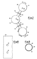
- Figure 7 shows some combustion chambers 17, 18 and 19, which belong to a non-annular gas turbine, each of which is connected to the next chamber by one of the flame-passage devices 10 according to the invention.
- the device 10 thus fulfils the requirements of integration with the other elements of the combustion system.
- the flame-passage tube 10 can be translated along almost all of its own length inside a liner body, thus releasing immediately the connection flanging 22 between the various cases 31, 32, relative to the combustion chambers 17, 18, and 19.
- Figure 8 represents the development of the liner 28 of one of the combustion chambers in figure 7, the latter being indicated by the reference number 17.
- This liner 28 has a circular hole 20, for connection to the cylindrical end 13 of the flame-passage tube 10, by means of interposition of the cylindrical collar 15.
- case 31 has an oval hole 21, for connection to the elliptical end 14 of the flame-passage tube 10, by means of interposition of the oval collar 16.
- the particular shape of the body of the flame-passage tube 11 is such that, assisted by added hard, anti-wear surface deposits, it permits a drastic reduction in the relative motion, which causes wear in the corresponding anchorage collars 15, 16, which form part of the liners 28, 29.
- the flame-passage device 10 thus consists of a metal tube 11, which is suitably perforated in order to obtain the correct cooling of the swirl cooling type, and has an oval end 14.
- the oval end 14 of the flame-passage tube 11 is provided with three rings, indicated respectively as 23, 24 and 25, for anchorage of the corresponding combustion chamber 17 to the case 31.
- the flame-passage device 10 also has a free end 13, with a cylindrical shape.
- the flame-passage device 10 is anchored to the case 31 of the corresponding combustion chamber 17 by means of use of a corresponding fork 26, as illustrated in figure 10.
- the flame passage tube 11 is inside the flanged pipe 27.
- an anti-wear deposit made of stellite 6 or another hard material is provided, in order to cover the contact surface in the interface with the collars 15 and 16 of the liners 28, 29, which are also provided with this deposit.
- the three rings 23, 24 and 25 on the oval end 14 of the flame-passage tube 11 permit anchorage of the entire flame-passage tube 11 by means of a single fork device 26, thus preventing use of the two fork devices which are necessary in the conventional embodiments.
- the oval cross-section makes it possible to prevent vibratory effects, combined with the tendency to rotation induced by the swirl cooling, from triggering spin of the flame-passage tube 11 in the collars 15, 16, with consequent wear, of the type found on machines which have been overhauled.
- the said flame-passage tube 11 When it is inserted in the machine, the said flame-passage tube 11 therefore connects an oval collar 16 of a liner 28, to a cylindrical collar 15 of the adjacent liner 29 (each liner 28, 29 thus has one cylindrical collar, and one oval collar, of the splash-cooled type), whereas it is connected by means of a retention fork 26 only on the oval end 14 side.
- This retention fork 26 can be extracted only in the direction of the cover 30, which closes it in operative conditions.
- the flame-passage device 10 thus consists altogether of:
- a flame-passage tube with a new design has therefore been created, which can be extracted simply by removing the covers.
- the aim was also to meet the requirements of the overall design specification, i.e. to provide the component designed with characteristics of long service life and functional efficiency which are clearly better than those of the components known at present according to the art.
Landscapes
- Engineering & Computer Science (AREA)
- Chemical & Material Sciences (AREA)
- Combustion & Propulsion (AREA)
- Mechanical Engineering (AREA)
- General Engineering & Computer Science (AREA)
- Turbine Rotor Nozzle Sealing (AREA)
- Gas Burners (AREA)
- Combustion Of Fluid Fuel (AREA)
- Chimneys And Flues (AREA)
Abstract
Description
- The present invention relates to a flame-passage device for non-annular gas turbine combustion chambers.
- The constant quest for increases in the performance levels of gas turbines, and in the intervals between the various stoppages for maintenance, as well as the pressing need to reduce pollutant emissions as far as possible, makes necessary optimisation of all the components which are inserted in the so-called hot gas path.
- In particular, the combustion system, which acts as an energiser for the thermal-carrier fluid, is the true heart of the turbine engine, and therefore defines its level of emission, and, according to the service life of its own components, the intervals of functioning between machine stoppages, in order to carry out inspections of the combustion chambers.
- The requirement to develop the machines in operation, with increases in the compression ratios and fire temperatures, are a further reason for emphasising the criticality of the hot components.
- Reduction of the emissions, with an increase in the service life of the components, and optionally also in the efficiency of the system, also constitutes a general target which undoubtedly has an impact on the clientele of heavy duty machines, and is a stimulating technological challenge for the designers.
- In particular, in the case of machines which have had a certain length of service, it is possible to gather sufficient statistical data to determine the parameters and details which are critical in achieving overall improvements, such as to justify the cost of the design and subsequent marketing, optionally in uprate packages for the aftermarket.
- A major technical problem therefore consists substantially of determining solutions which permit achievement of maximum satisfaction of the client for the three aforementioned aspects, all by means of innovative creations which are economically acceptable.
- In order better to understand the technical problems which are involved in the present invention, at this point reference is made to the following state of the art.
- The solutions which are currently used in order to achieve the three above-described objectives (greater efficiency, longer service life of the machine, and fewer pollutant emissions), are not in general combined in a single product, but are on the other hand implemented in ranges of alternative components.
- In order to increase the service life, and thus the intervals of inspection of the combustion chambers, use is made of materials, such as stellite 6, deposited onto elements which may become worn by relative vibratory motion, super-alloys with a nickel/cobalt base, with high levels of mechanical characteristics and of resistance to corrosion at high temperatures, additions of a ceramic type, to reduce the temperatures of the metal (for the same cooling flows), and optimisation of the design of the components, on the basis of experience acquired.
- A previous solution, consisting of six combustion chambers arranged in two rows of three parallel combustion chambers stacked on both sides of the machine, in an arrangement at right-angles to the machine axis, by means of interposition of 90° connection elbows between the liners and transition pieces, was then replaced by an arrangement characterised by chambers inclined by only a few degrees in relation to the machine axis, and insertion of the liners directly in the transition piece, and therefore without the need for further connection elements.
- Another arrangement is known from US-A-4 249 372.
- Particular problems of the known art also become apparent by taking into consideration the operations of fitting and removal of the various components.
- In the conventional case, the procedure followed consists of opening the covers of the chambers including burners, removing one of the liners of the chambers which are connected to the adjacent chambers by means of a single flame-passage tube, then removing the entire flame-passage unit from the flanged pipe which connects the two cases of the said chambers, such that the case of the said chambers has its liner removed, and the subsequent chamber is also connected at this point only by the flame-passage tube, for connection to the successive chamber.
- The procedure continues iteratively, with removal of all the liners and the corresponding crossfires.
- Since at this point the crossfires have been removed, the flanged pipes outside the latter are free to be disconnected, thus permitting removal also of the individual cases.
- However, the complexity and intricacy of this succession of removal operations should be noted.
- In particular, the arrangement of the combustion chambers in the gap between the flanging on the turbine case, and the pipe to supply induction air to the compressor (which is further limited in the lower area by the presence of the front support fork of the machine), makes it impossible to fit and remove the combustion chambers according to the method currently used for all the multi-canned applications.
- The object of the present invention is thus to provide a flame-passage device for non-annular gas turbine combustion chambers, comprising a combustion system which is innovative both from the point of view of the overall arrangement, and from that of its component elements.
- A further object of the invention is to provide a flame-passage device for non-annular gas turbine combustion chambers, which is designed particularly for the aftermarket, and is therefore easy to fit and remove.
- Another object of the invention is to provide a flame-passage device for non-annular gas turbine combustion chambers, which has a high level of efficiency and mechanical reliability.
- These and other objects are achieved by a flame-passage device for non-annular gas turbine combustion chambers, of the type comprising a tubular body, which is provided with a plurality of cooling holes, for cooling of the swirl-cooling type, wherein the said tubular body is inserted in a flanged pipe, which connects the cases of two successive combustion chambers, characterised in that it has a first end with a cylindrical shape, and a second end with an oval shape, wherein the second, oval end is provided with three rings, for anchorage of the corresponding combustion chamber to the case.
- According to a preferred embodiment of the present invention, a cylindrical collar can be fitted at the said first, cylindrical end of the said tubular body, and an oval collar can be fitted at the said second, oval end of the said tubular body.
- According to another preferred embodiment of the present invention, the cases which belong to each combustion chamber each have a circular hole, for connection to the cylindrical end of the said flame-passage tube, which takes place by means of interposition of the said cylindrical collar, and the cases of each combustion chamber each have an oval hole, for connection to the oval end of the said flame-passage tube, which takes place by means of interposition of the said oval collar.
- According to another preferred embodiment of the present invention, the three rings, which are present at the said second, oval end, permit anchorage of the corresponding combustion chamber to the case, by means of use of a corresponding fork.
- According to a further preferred embodiment of the present invention, on the ends of the said flame-passage tube, an anti-wear deposit made of stellite 6 or another hard material is provided, in order to cover the contact surface in the interface with the said collars of the liners.
- In addition, the flame-passage tube can be translated along almost the entire length inside a liner body, thus releasing immediately the connection flanging between the various cases of the combustion chambers.
- Further characteristics of the invention are defined in the claims attached to the present patent application.
- Further objects and advantages of the present invention, as well as its structural and functional characteristics, will become apparent by examining the following description and the drawings attached to it, which are provided purely by way of non-limiting, explanatory example, and in which:
- figure 1 represents a lateral view of a flame-passage tube for non-annular gas turbine combustion chambers, according to the present invention;
- figure 2 represents a plan view of the flame-passage tube in figure 1;
- figure 3 represents a plan view of an oval collar, to be fitted to the flame-passage tube in figure 1;
- figure 4 represents a view in cross-section, according to the plane IV-IV, of the oval collar in figure 3;
- figure 5 represents a plan view of a cylindrical collar, to be fitted to the flame-passage tube in figure 1;
- figure 6 represents a view in cross-section according to the plane VI-VI, of the cylindrical collar in figure 5;
- figure 7 represents a plan view of some combustion chambers which belong to a non-annular gas turbine, and are connected by the flame-passage device according to the invention;
- figure 8 represents the development of the liner of one of the combustion chambers in figure 7;
- figure 9 represents in cross-section one of the combustion chambers in figure 7; and finally,
- figure 10 represents a view partially in cross-section according to the plane X-X, of the flame-passage device for non-annular gas turbine combustion chambers, according to the present invention.
- With particular reference to the aforementioned figures, the flame-passage device for non-annular gas turbine combustion chambers, according to the present invention, is indicated globally by the
numerical reference 10. - The flame-
passage device 10 consists of atubular body 11, which is provided with a plurality of cooling holes 12, for cooling of the swirl cooling type. - The flame-
passage tube 10 has afirst end 13, which has a cylindrical shape, and asecond end 14, which has an oval shape. - At this
first end 13, there can be fitted acylindrical collar 15, which is represented in figures 3-4, whereas at the saidsecond end 14, there can be fitted anoval collar 16, which is represented in figures 5-6. - Figure 7 shows some
combustion chambers passage devices 10 according to the invention. - The
device 10 thus fulfils the requirements of integration with the other elements of the combustion system. - The flame-
passage tube 10 can be translated along almost all of its own length inside a liner body, thus releasing immediately the connection flanging 22 between thevarious cases combustion chambers - Figure 8 represents the development of the
liner 28 of one of the combustion chambers in figure 7, the latter being indicated by thereference number 17. - This
liner 28 has acircular hole 20, for connection to thecylindrical end 13 of the flame-passage tube 10, by means of interposition of thecylindrical collar 15. - Similarly, the
case 31 has anoval hole 21, for connection to theelliptical end 14 of the flame-passage tube 10, by means of interposition of theoval collar 16. - The particular shape of the body of the flame-
passage tube 11 is such that, assisted by added hard, anti-wear surface deposits, it permits a drastic reduction in the relative motion, which causes wear in thecorresponding anchorage collars liners - It will be appreciated that these
collars - The flame-
passage device 10 thus consists of ametal tube 11, which is suitably perforated in order to obtain the correct cooling of the swirl cooling type, and has anoval end 14. - The
oval end 14 of the flame-passage tube 11 is provided with three rings, indicated respectively as 23, 24 and 25, for anchorage of thecorresponding combustion chamber 17 to thecase 31. - The flame-
passage device 10 also has afree end 13, with a cylindrical shape. - The flame-
passage device 10 is anchored to thecase 31 of thecorresponding combustion chamber 17 by means of use of acorresponding fork 26, as illustrated in figure 10. - In addition, in the assembled configuration, the
flame passage tube 11 is inside theflanged pipe 27. - On both the
ends collars liners - The three
rings oval end 14 of the flame-passage tube 11 permit anchorage of the entire flame-passage tube 11 by means of asingle fork device 26, thus preventing use of the two fork devices which are necessary in the conventional embodiments. - The oval cross-section makes it possible to prevent vibratory effects, combined with the tendency to rotation induced by the swirl cooling, from triggering spin of the flame-
passage tube 11 in thecollars - When it is inserted in the machine, the said flame-
passage tube 11 therefore connects anoval collar 16 of aliner 28, to acylindrical collar 15 of the adjacent liner 29 (eachliner retention fork 26 only on theoval end 14 side. - This
retention fork 26 can be extracted only in the direction of thecover 30, which closes it in operative conditions. - For the removal of the combustion chamber it is thus apparent that, when the cover of one of the chambers has been removed (those which are uppermost, for example the
cover 30 in figure 10), when thefork 26 is removed, the flame-passage tube 11 is slid inside theliner 29 of thelower chamber 18, until it abuts therings cylindrical collar 15. - This makes it possible to release completely the flanging of the outer cases, which can then be removed easily.
- The flame-
passage device 10 according to the present invention thus consists altogether of: - a flame-
passage tube 11, with acylindrical end 13 and anelliptical end 14, provided with threerings collars rings - a pair of
collars passage tube 11, and are provided with an anti-wear deposit; and - a
retention fork 26, with a geometry which is suitable for anchorage to the said threerings - The description provided makes apparent the characteristics and advantages of the flame-passage device for non-annular gas turbine combustion chambers which is the subject of the present invention.
- The following concluding comments and observations are made, in order to define the said advantages more accurately and clearly.
- Firstly, in the case of the machines which use devices according to the known art, it is not possible to extract liners and the corresponding cases in successive stages.
- A flame-passage tube with a new design has therefore been created, which can be extracted simply by removing the covers.
- With reference to the simplification of the procedures for fitting and removal, the aim was also to meet the requirements of the overall design specification, i.e. to provide the component designed with characteristics of long service life and functional efficiency which are clearly better than those of the components known at present according to the art.
- In this inventive embodiment, all the solutions presently available according to the state of the art have been implemented for the three above-described objectives (increased efficiency, longer service life of the machine, and fewer pollutant emissions), such as to obtain a unit device which includes all the advantages thus accumulated.
- Since this application is designed for the aftermarket, and thus has pre-defined constraints of geometries and functional parameters, the design of the component elements, and their incorporation in the system, has led to the development of details which are innovative in terms of design and functionality.
- To summarise, a flame-passage device has been provided, which makes it possible to obtain the major advantages of easy fitting and removal, as well as improved efficiency and mechanical reliability of the machine.
- It is apparent that many variations can be made to the flame-passage device for non-annular gas turbine combustion chambers which is the subject of the present invention, without departing from the principles of novelty which are inherent in the inventive concept illustrated.
- Finally, it is apparent that in the practical embodiment of the invention, any materials, forms and dimensions of the details illustrated can be used, according to requirements, and can be replaced by others which are equivalent from a technical point of view.
- The scope of the invention is defined by the attached claims.
Claims (9)
- Flame-passage device (10) for non-annular gas turbine combustion chambers, of the type comprising a tubular body (11), which is provided with a plurality of cooling holes (12), for cooling of the swirl-cooling type, wherein the tubular body (11) is inserted in a flanged pipe (27), which connects the cases (31, 32) of two successive combustion chambers (17, 18), characterised in that it has a first end (13) with a cylindrical shape, and a second end (14) with an oval shape, wherein the second, oval end (14) is provided with three rings (23, 24, 25), for anchorage of the corresponding combustion chamber (17) to the case (31).
- Flame-passage device (10) according to claim 1, characterised in that a cylindrical collar (15) can be fitted to the said first, cylindrical end (13) of the said tubular body (11).
- Flame-passage device (10) according to claim 1, characterised in that an oval collar (16) can be fitted to the said second, oval end (14) of the said tubular body (11).
- Flame-passage device (10) according to claim 1 and claim 2, characterised in that the cases (31, 32) which belong to each combustion chamber (17, 18, 19) each have a circular hole (20), for connection to the cylindrical end (13) of the said flame-passage tube (10), which takes place by means of interposition of the said cylindrical collar (15).
- Flame-passage device (10) according to claim 4, characterised in that the cases which belong to each combustion chamber (17, 18, 19) each have an oval hole (21), for connection to the said oval end (14) of the said flame-passage tube (10), which takes place by means of interposition of the said oval collar (16).
- Flame-passage device (10) according to the preceding claims, characterised in that the said three rings (23, 24, 25) which are present at the said oval end (14) permit anchorage of the corresponding combustion chamber (17) to the case (31), by means of use of a corresponding fork (26).
- Flame-passage device (10) according to the preceding claims, characterised in that, on both ends (13, 14) of the said flame-passage device (11), an anti-wear deposit is provided, which is made of stellite 6 or another hard material, in order to cover the contact surface in the interface with the said collars (15, 16) of the liners (28, 29).
- Flame-passage device (10) according to claim 1, characterised in that the said collars (15, 16) of the liners (28, 29) are provided with an anti-wear deposit.
- Flame-passage device (10) according to claim 1, characterised in that it can be translated along virtually the entire length inside a liner body (28, 29), thus releasing immediately the connection flanging (22) between the various cases (31, 32) of the combustion chambers (17, 18, 19).
Applications Claiming Priority (3)
| Application Number | Priority Date | Filing Date | Title |
|---|---|---|---|
| IT2000MI001241A IT1317775B1 (en) | 2000-06-02 | 2000-06-02 | FLAME ARROW DEVICE FOR COMBUSTION CHAMBERS OF NONANULAR GAS TURBINES |
| ITMI000124 | 2000-06-02 | ||
| PCT/EP2001/005790 WO2001092787A1 (en) | 2000-06-02 | 2001-05-18 | Flame-passage device for non-annular gas turbine combustion chambers |
Publications (2)
| Publication Number | Publication Date |
|---|---|
| EP1290377A1 EP1290377A1 (en) | 2003-03-12 |
| EP1290377B1 true EP1290377B1 (en) | 2006-11-02 |
Family
ID=11445183
Family Applications (1)
| Application Number | Title | Priority Date | Filing Date |
|---|---|---|---|
| EP01936379A Expired - Lifetime EP1290377B1 (en) | 2000-06-02 | 2001-05-18 | Flame-passage device for non-annular gas turbine combustion chambers |
Country Status (12)
| Country | Link |
|---|---|
| US (1) | US6834491B2 (en) |
| EP (1) | EP1290377B1 (en) |
| AT (1) | ATE344424T1 (en) |
| AU (1) | AU2001262304A1 (en) |
| BR (1) | BR0111269A (en) |
| DE (1) | DE60124250T2 (en) |
| EG (1) | EG22763A (en) |
| IT (1) | IT1317775B1 (en) |
| MX (1) | MXPA02011869A (en) |
| NO (1) | NO322604B1 (en) |
| RU (1) | RU2267711C2 (en) |
| WO (1) | WO2001092787A1 (en) |
Families Citing this family (14)
| Publication number | Priority date | Publication date | Assignee | Title |
|---|---|---|---|---|
| GB2443839A (en) * | 2006-11-17 | 2008-05-21 | Siemens Ag | Interconnected Combustion Chambers |
| WO2008128140A1 (en) * | 2007-04-13 | 2008-10-23 | The Regents Of The University Of Michigan | Delivery device and method for forming the same |
| US8220246B2 (en) * | 2009-09-21 | 2012-07-17 | General Electric Company | Impingement cooled crossfire tube assembly |
| US20130333389A1 (en) * | 2012-06-15 | 2013-12-19 | General Electric Company | Cross fire tube retention system for a gas turbine engine |
| JP5911387B2 (en) * | 2012-07-06 | 2016-04-27 | 三菱日立パワーシステムズ株式会社 | Gas turbine combustor and gas turbine combustor operating method |
| US20140137536A1 (en) * | 2012-11-21 | 2014-05-22 | General Electric Company | Super telescoping cross-fire tube and method of assembling a combustor structure |
| US9353952B2 (en) * | 2012-11-29 | 2016-05-31 | General Electric Company | Crossfire tube assembly with tube bias between adjacent combustors |
| WO2015100280A1 (en) | 2013-12-24 | 2015-07-02 | Viking At, Llc | Mechanically amplified smart material actuator utilizing layered web assembly |
| GB201410586D0 (en) | 2014-06-13 | 2014-07-30 | Rolls Royce Plc | Duct |
| JP6521283B2 (en) * | 2014-09-25 | 2019-05-29 | 三菱日立パワーシステムズ株式会社 | Combustor, gas turbine |
| WO2016156285A1 (en) * | 2015-03-30 | 2016-10-06 | Nuovo Pignone Tecnologie Srl | Interchangeable liner support for gas turbine combustors |
| JP6965108B2 (en) * | 2017-11-08 | 2021-11-10 | 三菱パワー株式会社 | Gas turbine combustor |
| KR102125448B1 (en) * | 2018-09-11 | 2020-06-22 | 두산중공업 주식회사 | Cross-fire tube, combustor and gas turbine including the same |
| RU194926U1 (en) * | 2019-10-15 | 2019-12-30 | Публичное Акционерное Общество "Одк-Сатурн" | FLAME CONVERTER ASSEMBLY ASSEMBLY WITH HEAT PIPE COMBUSTION CHAMBER OF A GAS TURBINE ENGINE |
Family Cites Families (11)
| Publication number | Priority date | Publication date | Assignee | Title |
|---|---|---|---|---|
| US2832195A (en) * | 1956-04-16 | 1958-04-29 | Gen Electric | Cross-ignition tube assembly for gas turbine combustion system |
| US4249372A (en) * | 1979-07-16 | 1981-02-10 | General Electric Company | Cross-ignition assembly for combustion apparatus |
| US5154049A (en) * | 1990-07-10 | 1992-10-13 | General Electric Company | Tube mounting apparatus including a wire retainer |
| KR940001925B1 (en) * | 1990-07-10 | 1994-03-11 | 제너럴 일렉트릭 캄파니 | Tube mounting apparatus including a wire retainer |
| GB9021201D0 (en) * | 1990-09-28 | 1990-11-14 | Ruston Gas Turbines Ltd | Gas turbine combustors |
| EP0488556B1 (en) * | 1990-11-27 | 1997-07-16 | General Electric Company | Premixed secondary fuel nozzle with integral swirler |
| RU2027114C1 (en) * | 1992-01-13 | 1995-01-20 | Акционерное общество закрытого типа "Минитокс" | Combustion chamber |
| US5402635A (en) * | 1993-09-09 | 1995-04-04 | Westinghouse Electric Corporation | Gas turbine combustor with cooling cross-flame tube connector |
| US5896742A (en) * | 1997-03-20 | 1999-04-27 | General Electric Co. | Tapered cross-fire tube for gas turbine combustors |
| US5964250A (en) * | 1997-12-01 | 1999-10-12 | General Electric Company | Low leakage, articulating fluid transfer tube |
| GB2339468B (en) * | 1998-07-11 | 2002-04-24 | Alstom Gas Turbines Ltd | Gas-turbine engine combustion system |
-
2000
- 2000-06-02 IT IT2000MI001241A patent/IT1317775B1/en active
-
2001
- 2001-05-18 RU RU2002135613/06A patent/RU2267711C2/en not_active IP Right Cessation
- 2001-05-18 WO PCT/EP2001/005790 patent/WO2001092787A1/en not_active Ceased
- 2001-05-18 BR BR0111269-4A patent/BR0111269A/en not_active Application Discontinuation
- 2001-05-18 EP EP01936379A patent/EP1290377B1/en not_active Expired - Lifetime
- 2001-05-18 AT AT01936379T patent/ATE344424T1/en active
- 2001-05-18 DE DE60124250T patent/DE60124250T2/en not_active Expired - Lifetime
- 2001-05-18 MX MXPA02011869A patent/MXPA02011869A/en not_active Application Discontinuation
- 2001-05-18 AU AU2001262304A patent/AU2001262304A1/en not_active Abandoned
- 2001-05-18 US US10/296,709 patent/US6834491B2/en not_active Expired - Fee Related
- 2001-06-02 EG EG20010585A patent/EG22763A/en active
-
2002
- 2002-11-29 NO NO20025741A patent/NO322604B1/en not_active IP Right Cessation
Also Published As
| Publication number | Publication date |
|---|---|
| RU2267711C2 (en) | 2006-01-10 |
| ITMI20001241A1 (en) | 2001-12-02 |
| NO20025741L (en) | 2003-01-27 |
| MXPA02011869A (en) | 2003-04-10 |
| ATE344424T1 (en) | 2006-11-15 |
| NO322604B1 (en) | 2006-10-30 |
| AU2001262304A1 (en) | 2001-12-11 |
| DE60124250T2 (en) | 2007-05-24 |
| ITMI20001241A0 (en) | 2000-06-02 |
| US20040098990A1 (en) | 2004-05-27 |
| NO20025741D0 (en) | 2002-11-29 |
| EP1290377A1 (en) | 2003-03-12 |
| US6834491B2 (en) | 2004-12-28 |
| DE60124250D1 (en) | 2006-12-14 |
| EG22763A (en) | 2003-07-30 |
| WO2001092787A1 (en) | 2001-12-06 |
| BR0111269A (en) | 2003-06-10 |
| IT1317775B1 (en) | 2003-07-15 |
Similar Documents
| Publication | Publication Date | Title |
|---|---|---|
| US6834491B2 (en) | Flame-passage device for non-annular gas turbine combustion chambers | |
| EP1295014B1 (en) | Transition piece for non-annular gas turbine combustion chambers | |
| US8327648B2 (en) | Combustor liner with integrated anti-rotation and removal feature | |
| CN204534660U (en) | For the interface assembly of burner, burner arrangement and gas-turbine unit | |
| EP2489938A2 (en) | Method and apparatus for mounting transition piece in combustor | |
| US8240974B2 (en) | Cold air buffer supply tube | |
| JP5149596B2 (en) | Combustor dome mixer holding means | |
| CA2596484A1 (en) | Strainer for a gas turbine engine | |
| US20200347750A1 (en) | Carbon seal spring retention | |
| CN106545367B (en) | Gas turbine and the fastening assembly for it | |
| CN106471312B (en) | Assemblies for turbine engine combustion chambers including bosses and annular elements | |
| EP1394470A3 (en) | Multiple-domes annular combustor for a gas turbine engine | |
| US20220034261A1 (en) | Combustor cap assembly having impingement plate with cooling tubes | |
| KR20120019382A (en) | Combustor liner concentric support and method | |
| CA2964636C (en) | Small exit duct for a reverse flow combustor with integrated fastening elements | |
| US2729938A (en) | Combustion chamber crossover tube | |
| JP4749313B2 (en) | Combustor dome repair method | |
| CN103807023A (en) | A system for cooling a hot gas path component, corresponding gas turbine combustor and cooling method | |
| CA2941224A1 (en) | Ceramic matrix composite ring shroud retention methods-finger seals with stepped shroud interface | |
| CN108119238B (en) | Impingement insert for a gas turbine engine | |
| US20220034509A1 (en) | Impingement plate with cooling tubes and related insert for impingement plate | |
| CN118423717B (en) | Long-life backflow combustion chamber | |
| EP0962699A2 (en) | A fuel injector | |
| SE455219B (en) | COMPRESSOR GLASS CRANE IN A COMBUSTION TURBINE |
Legal Events
| Date | Code | Title | Description |
|---|---|---|---|
| PUAI | Public reference made under article 153(3) epc to a published international application that has entered the european phase |
Free format text: ORIGINAL CODE: 0009012 |
|
| 17P | Request for examination filed |
Effective date: 20030102 |
|
| AK | Designated contracting states |
Kind code of ref document: A1 Designated state(s): AT BE CH CY DE DK ES FI FR GB GR IE IT LI LU MC NL PT SE TR |
|
| AX | Request for extension of the european patent |
Extension state: AL LT LV MK RO SI |
|
| RBV | Designated contracting states (corrected) |
Designated state(s): AT DE GB NL |
|
| GRAP | Despatch of communication of intention to grant a patent |
Free format text: ORIGINAL CODE: EPIDOSNIGR1 |
|
| GRAS | Grant fee paid |
Free format text: ORIGINAL CODE: EPIDOSNIGR3 |
|
| GRAA | (expected) grant |
Free format text: ORIGINAL CODE: 0009210 |
|
| AK | Designated contracting states |
Kind code of ref document: B1 Designated state(s): AT DE GB NL |
|
| REG | Reference to a national code |
Ref country code: GB Ref legal event code: FG4D |
|
| REF | Corresponds to: |
Ref document number: 60124250 Country of ref document: DE Date of ref document: 20061214 Kind code of ref document: P |
|
| PLBE | No opposition filed within time limit |
Free format text: ORIGINAL CODE: 0009261 |
|
| STAA | Information on the status of an ep patent application or granted ep patent |
Free format text: STATUS: NO OPPOSITION FILED WITHIN TIME LIMIT |
|
| 26N | No opposition filed |
Effective date: 20070803 |
|
| PGFP | Annual fee paid to national office [announced via postgrant information from national office to epo] |
Ref country code: DE Payment date: 20150528 Year of fee payment: 15 Ref country code: GB Payment date: 20150527 Year of fee payment: 15 |
|
| PGFP | Annual fee paid to national office [announced via postgrant information from national office to epo] |
Ref country code: NL Payment date: 20150526 Year of fee payment: 15 Ref country code: AT Payment date: 20150505 Year of fee payment: 15 |
|
| REG | Reference to a national code |
Ref country code: DE Ref legal event code: R119 Ref document number: 60124250 Country of ref document: DE |
|
| REG | Reference to a national code |
Ref country code: NL Ref legal event code: MM Effective date: 20160601 |
|
| REG | Reference to a national code |
Ref country code: AT Ref legal event code: MM01 Ref document number: 344424 Country of ref document: AT Kind code of ref document: T Effective date: 20160518 |
|
| GBPC | Gb: european patent ceased through non-payment of renewal fee |
Effective date: 20160518 |
|
| PG25 | Lapsed in a contracting state [announced via postgrant information from national office to epo] |
Ref country code: NL Free format text: LAPSE BECAUSE OF NON-PAYMENT OF DUE FEES Effective date: 20160601 Ref country code: AT Free format text: LAPSE BECAUSE OF NON-PAYMENT OF DUE FEES Effective date: 20160518 |
|
| PG25 | Lapsed in a contracting state [announced via postgrant information from national office to epo] |
Ref country code: DE Free format text: LAPSE BECAUSE OF NON-PAYMENT OF DUE FEES Effective date: 20161201 |
|
| PG25 | Lapsed in a contracting state [announced via postgrant information from national office to epo] |
Ref country code: GB Free format text: LAPSE BECAUSE OF NON-PAYMENT OF DUE FEES Effective date: 20160518 |