EP1290327B1 - Method and device for exhaust recycling and supercharged diesel engine - Google Patents
Method and device for exhaust recycling and supercharged diesel engine Download PDFInfo
- Publication number
- EP1290327B1 EP1290327B1 EP01934744A EP01934744A EP1290327B1 EP 1290327 B1 EP1290327 B1 EP 1290327B1 EP 01934744 A EP01934744 A EP 01934744A EP 01934744 A EP01934744 A EP 01934744A EP 1290327 B1 EP1290327 B1 EP 1290327B1
- Authority
- EP
- European Patent Office
- Prior art keywords
- venturi
- channel
- egr
- wall portion
- gases
- Prior art date
- Legal status (The legal status is an assumption and is not a legal conclusion. Google has not performed a legal analysis and makes no representation as to the accuracy of the status listed.)
- Expired - Lifetime
Links
- 238000000034 method Methods 0.000 title claims abstract description 11
- 238000004064 recycling Methods 0.000 title claims abstract description 8
- 239000007789 gas Substances 0.000 claims abstract description 43
- 238000002485 combustion reaction Methods 0.000 claims abstract description 11
- 239000012528 membrane Substances 0.000 claims description 5
- 238000011144 upstream manufacturing Methods 0.000 claims description 5
- MWUXSHHQAYIFBG-UHFFFAOYSA-N nitrogen oxide Inorganic materials O=[N] MWUXSHHQAYIFBG-UHFFFAOYSA-N 0.000 description 3
- IJGRMHOSHXDMSA-UHFFFAOYSA-N Atomic nitrogen Chemical compound N#N IJGRMHOSHXDMSA-UHFFFAOYSA-N 0.000 description 2
- 238000010276 construction Methods 0.000 description 2
- 238000005086 pumping Methods 0.000 description 2
- GQPLMRYTRLFLPF-UHFFFAOYSA-N Nitrous Oxide Chemical class [O-][N+]#N GQPLMRYTRLFLPF-UHFFFAOYSA-N 0.000 description 1
- 229910000639 Spring steel Inorganic materials 0.000 description 1
- 230000001276 controlling effect Effects 0.000 description 1
- 238000001816 cooling Methods 0.000 description 1
- 238000006073 displacement reaction Methods 0.000 description 1
- 230000000694 effects Effects 0.000 description 1
- 239000000446 fuel Substances 0.000 description 1
- 238000003780 insertion Methods 0.000 description 1
- 230000037431 insertion Effects 0.000 description 1
- 238000009434 installation Methods 0.000 description 1
- 239000000203 mixture Substances 0.000 description 1
- 229910052757 nitrogen Inorganic materials 0.000 description 1
- 230000001105 regulatory effect Effects 0.000 description 1
- 230000000717 retained effect Effects 0.000 description 1
- 238000007493 shaping process Methods 0.000 description 1
- 230000003068 static effect Effects 0.000 description 1
- 239000002699 waste material Substances 0.000 description 1
Images


Classifications
-
- F—MECHANICAL ENGINEERING; LIGHTING; HEATING; WEAPONS; BLASTING
- F02—COMBUSTION ENGINES; HOT-GAS OR COMBUSTION-PRODUCT ENGINE PLANTS
- F02D—CONTROLLING COMBUSTION ENGINES
- F02D9/00—Controlling engines by throttling air or fuel-and-air induction conduits or exhaust conduits
- F02D9/08—Throttle valves specially adapted therefor; Arrangements of such valves in conduits
- F02D9/18—Throttle valves specially adapted therefor; Arrangements of such valves in conduits having elastic-wall valve members
-
- F—MECHANICAL ENGINEERING; LIGHTING; HEATING; WEAPONS; BLASTING
- F02—COMBUSTION ENGINES; HOT-GAS OR COMBUSTION-PRODUCT ENGINE PLANTS
- F02D—CONTROLLING COMBUSTION ENGINES
- F02D21/00—Controlling engines characterised by their being supplied with non-airborne oxygen or other non-fuel gas
- F02D21/06—Controlling engines characterised by their being supplied with non-airborne oxygen or other non-fuel gas peculiar to engines having other non-fuel gas added to combustion air
- F02D21/08—Controlling engines characterised by their being supplied with non-airborne oxygen or other non-fuel gas peculiar to engines having other non-fuel gas added to combustion air the other gas being the exhaust gas of engine
-
- F—MECHANICAL ENGINEERING; LIGHTING; HEATING; WEAPONS; BLASTING
- F02—COMBUSTION ENGINES; HOT-GAS OR COMBUSTION-PRODUCT ENGINE PLANTS
- F02M—SUPPLYING COMBUSTION ENGINES IN GENERAL WITH COMBUSTIBLE MIXTURES OR CONSTITUENTS THEREOF
- F02M26/00—Engine-pertinent apparatus for adding exhaust gases to combustion-air, main fuel or fuel-air mixture, e.g. by exhaust gas recirculation [EGR] systems
- F02M26/13—Arrangement or layout of EGR passages, e.g. in relation to specific engine parts or for incorporation of accessories
- F02M26/17—Arrangement or layout of EGR passages, e.g. in relation to specific engine parts or for incorporation of accessories in relation to the intake system
- F02M26/19—Means for improving the mixing of air and recirculated exhaust gases, e.g. venturis or multiple openings to the intake system
-
- F—MECHANICAL ENGINEERING; LIGHTING; HEATING; WEAPONS; BLASTING
- F02—COMBUSTION ENGINES; HOT-GAS OR COMBUSTION-PRODUCT ENGINE PLANTS
- F02M—SUPPLYING COMBUSTION ENGINES IN GENERAL WITH COMBUSTIBLE MIXTURES OR CONSTITUENTS THEREOF
- F02M35/00—Combustion-air cleaners, air intakes, intake silencers, or induction systems specially adapted for, or arranged on, internal-combustion engines
- F02M35/10—Air intakes; Induction systems
- F02M35/10209—Fluid connections to the air intake system; their arrangement of pipes, valves or the like
- F02M35/10222—Exhaust gas recirculation [EGR]; Positive crankcase ventilation [PCV]; Additional air admission, lubricant or fuel vapour admission
-
- F—MECHANICAL ENGINEERING; LIGHTING; HEATING; WEAPONS; BLASTING
- F02—COMBUSTION ENGINES; HOT-GAS OR COMBUSTION-PRODUCT ENGINE PLANTS
- F02M—SUPPLYING COMBUSTION ENGINES IN GENERAL WITH COMBUSTIBLE MIXTURES OR CONSTITUENTS THEREOF
- F02M26/00—Engine-pertinent apparatus for adding exhaust gases to combustion-air, main fuel or fuel-air mixture, e.g. by exhaust gas recirculation [EGR] systems
- F02M26/02—EGR systems specially adapted for supercharged engines
- F02M26/04—EGR systems specially adapted for supercharged engines with a single turbocharger
- F02M26/05—High pressure loops, i.e. wherein recirculated exhaust gas is taken out from the exhaust system upstream of the turbine and reintroduced into the intake system downstream of the compressor
-
- F—MECHANICAL ENGINEERING; LIGHTING; HEATING; WEAPONS; BLASTING
- F02—COMBUSTION ENGINES; HOT-GAS OR COMBUSTION-PRODUCT ENGINE PLANTS
- F02M—SUPPLYING COMBUSTION ENGINES IN GENERAL WITH COMBUSTIBLE MIXTURES OR CONSTITUENTS THEREOF
- F02M26/00—Engine-pertinent apparatus for adding exhaust gases to combustion-air, main fuel or fuel-air mixture, e.g. by exhaust gas recirculation [EGR] systems
- F02M26/13—Arrangement or layout of EGR passages, e.g. in relation to specific engine parts or for incorporation of accessories
- F02M26/22—Arrangement or layout of EGR passages, e.g. in relation to specific engine parts or for incorporation of accessories with coolers in the recirculation passage
- F02M26/23—Layout, e.g. schematics
-
- Y—GENERAL TAGGING OF NEW TECHNOLOGICAL DEVELOPMENTS; GENERAL TAGGING OF CROSS-SECTIONAL TECHNOLOGIES SPANNING OVER SEVERAL SECTIONS OF THE IPC; TECHNICAL SUBJECTS COVERED BY FORMER USPC CROSS-REFERENCE ART COLLECTIONS [XRACs] AND DIGESTS
- Y02—TECHNOLOGIES OR APPLICATIONS FOR MITIGATION OR ADAPTATION AGAINST CLIMATE CHANGE
- Y02T—CLIMATE CHANGE MITIGATION TECHNOLOGIES RELATED TO TRANSPORTATION
- Y02T10/00—Road transport of goods or passengers
- Y02T10/10—Internal combustion engine [ICE] based vehicles
- Y02T10/12—Improving ICE efficiencies
Definitions
- This invention concerns a method and a device according to the preambles of claims 1 and 6, respectively. It also concerns a supercharged engine including such a device.
- US-A-5 611 203 and US-A-5 611 204 could be mentioned as previously known art with respect to this invention.
- These documents describe how exhaust gases are recycled to the intake in turbo-supercharged diesel engines through a venturi device or any other kind of ejector being placed in the intake channel.
- the system according to these documents uses the low static pressure prevailing in a certain section of the ejector device for pumping-in an EGR flow into the charged air.
- the use of a valve blade in a by-pass channel brings along a pressure drop with resulting power waste for the engine.
- venturi arrangement US-A- 4 094 285 As prior art relating to venturi arrangement US-A- 4 094 285 can be mentioned.
- This arrangement includes in a carburettor having a movable vane which together with a fixed wall constitutes a venturi for mixing the fuel with the air, in a manner conventional for carburettors.
- the main body of the carburettor is provided with an outlet from an exhaust gas passageway positioned between the venturi and a throttle valve.
- the high speed of the gas mixture from the venturi will cause swirls that will enable efficient mixing with the exhaust gases.
- this arrangement will not facilitate transport of exhaust gases from the exhaust to the intake when the pressure in the intake system is higher than in the exhaust system.
- the invention makes it possible to minimise flow resistance losses since valve blades and similar control devices become unnecessary. Further, all intake air may be used for controlled EGR pumping in the venturi since no by-pass channel needs to be arranged. This gives great advantages since the pressure drop over the venturi device may be held at a minimum. Altogether the result will be enhanced engine performance.
- the adjustment is preferably controlled by a suitable sequence being programmed in the usual engine control computer, said sequence preferably using data being supplied by the ordinary parameter sensors of the engine.
- the channel for supplying EGR gases into the venturi device may be placed in a fixed or movable wall depending on what is suitable in a specific installation.
- venturi wall has a sideward recess wherein the adjustable wall portion is variably insertable. This way simple construction is achieved, making it possible for the venturi to be in principle out of function with resulting minimal pressure fall when the adjustable wall portion is entirely inserted into the recess.
- the upstream portion of the adjustable wall portion is formed such that together with the adjoining wall of the recess, in inserted positions of the insertable wall portion, it forms a space where a natural vortex may be formed and stay in operation. This may be obtained for example by having these wall portions forming a space with essentially equilateral triangular section, that is that the surfaces includes an angle of about 60°.
- a deformable membrane may be provided, which in a bridging manner connects the upstream portion of the adjustable wall portion with the adjoining wall of the recess.
- a deformable membrane may be provided, which in a bridging manner connects the upstream portion of the adjustable wall portion with the adjoining wall of the recess.
- the section of the venturi is essentially rectangular with adjustable height. This geometry gives simple construction and adjustability.
- Fig. 1 shows diagrammatically a combustion engine 1 of the piston engine type with cylinders arranged in a straight inline cylinder block.
- the engine is a four-stroke diesel engine adapted for a heavy vehicle such as a truck or a bus.
- Each cylinder is in its respective cylinder head in a conventional manner provided with at least one intake valve for supply of combustion air and at least one exhaust valve for discharge of exhaust gases from the combustion.
- An intake channel 2 leads the intake air to the cylinders whereas an exhaust collector 3 leads the exhaust gases from the cylinders to the turbine T and subsequently to the exhaust pipe.
- a transfer channel 4 is arranged for recycling EGR gases from the exhaust side of the cylinders to their intake side.
- the transfer channel 4 debouches in the intake channel 2 after a charging air cooler 5 and before a manifold to the cylinders.
- An EGR control valve 6 is positioned in the transfer channel whereby the transfer may be disconnected and possibly controlled to a certain extent.
- the transfer channel 4 debouches in a section of the intake channel wherein venturi 9 is arranged in such a way that the flow of intake gases, which are charged by the compressor C, is modified so as to create a negative pressure at the passage of the venturi. This is because the air at the passage of a convex curved portion will be given an increased speed.
- the EGR gases are led into said section in a portion in connection with the venturi where thus a negative pressure prevails.
- S indicates a control computer for controlling the venturi as a response to parameter signals from the engine.
- the venturi 9 is shown in more detail in Fig. 2, where an adjustable wall portion 10 is shown in a position 10', where it is brought into the channel 2 as much as possible and a position 10", where it is brought out from the channel 2 as much as possible with respect to a recess 12.
- the EGR transfer channel 4 debouches just about opposite that portion of the venturi 9 where the greatest negative pressure prevails. It is preferred that the channel 4 is arranged in a fixed wall 20 in the venturi but it may also debouch in the upper surface of the adjustable wall portion 10 (not shown). It is also preferred that the opening of the channel 4 in the venturi is directed in the flow direction in order to enhance transfer conditions.
- the wall portion 9 indicates a pivoting shaft whereby the wall portion 9 may be adjusted for regulating the amount/portion of supplied EGR gases.
- the most inserted position 10' results in a greater negative pressure and a greater content of supplied EGR gases, whereas the brought out position 10" results in smaller or possibly no amount of supplied EGR gases at all.
- the section through A - A of the shown venturi is rectangular which means that the surface of the wall portion 10, which is directed against the channel, is single-curved.
- the shape of this surface and its extension in the length direction and height direction is to be tested and dimensioned outgoing from engine data and desired EGR mixing conditions.
- the recess 12 thus serves for receiving the wall portion 10 in different retracted positions. It is preferred that the upstream portion 14 of the wall portion and the adjoining surface 13 of the recess in different retracted positions form a space having a section wherein a natural vortex V may be formed and be retained in operation. This gives an undisturbed operation without unwanted pressure fluctuations, which would otherwise occur if unstable vortices would be formed in this position.
- Control of the amount of exhaust gases to be recycled is accomplished by the control system S (Fig. 1), which in a per see known manner communicates with sensors for sensing suitable engine parameters.
- the cooler 7 is arranged for cooling the recycled EGR gases.
- Fig. 2 (and 3) also shows a setting means 17, which is controlled by the control system S (Fig. 1) and may be provided with an electrically hydraulically or pneumatically operated motor.
- Fig. 3 shows an embodiment wherein a deformable membrane 15 is attached which provides a curve adjoining between the wall portion 10 and the fixed wall 16.
- the membrane may for example be made of spring steel.
- the shape of the venturi 9 may thus vary depending on the present application. This also concerns the shape of the channel, but with the preferred embodiment, having a channel with a rectangular section, similar advantageous flow conditions are created over the width of the wall portion 10.
- the movement pattern of the wall portion 10 may be different if insertion into the channel 2 is accomplished in any other way, for example by displacement. Larger portions of the wall may also be deformable besides only the membrane 15.
Landscapes
- Engineering & Computer Science (AREA)
- Chemical & Material Sciences (AREA)
- Combustion & Propulsion (AREA)
- Mechanical Engineering (AREA)
- General Engineering & Computer Science (AREA)
- Exhaust-Gas Circulating Devices (AREA)
- Output Control And Ontrol Of Special Type Engine (AREA)
- Control Of Throttle Valves Provided In The Intake System Or In The Exhaust System (AREA)
Abstract
Description
- This invention concerns a method and a device according to the preambles of
claims 1 and 6, respectively. It also concerns a supercharged engine including such a device. - In turbo-supercharged diesel engines it is previously known to recycle exhaust gases to the engine inlet in order to reduce contents of nitrous oxides in the exhaust gases. Hereby the recycled exhaust gases function so as to lower the combustion temperature resulting in that a smaller amount of the nitrogen in the inlet air can be converted into nitrogen oxides. This process, usually called EGR (exhaust gas recirculation) has often been used in Otto engines as a relatively simple way of reducing the contents of harmful exhaust gas emissions. In diesel engines, on the other hand, this technique has not been employed to such a great extent depending i.a. on the fact that there are particular problems associated with these engines, making Otto engine solution not directly applicable in diesel engines.
- One of these particular problems is that the combustion in diesel engines normally occurs with excess air. This indirectly results in need of transferring relatively large amounts of exhaust gases during a relatively large operating range of the engine in order to achieve the desired function. This problem is accentuated in case of an engine of the supercharged type, because in that case the pressure in the intake system of the engine is greater than the pressure in the exhaust gas system during a great part of the operating range.
- It is previously known to use a separate supercharging device in order to obtain the desired increase of exhaust gas pressure, for example through
WO96/18030 WO96/18031 - Also
US-A-5 611 203 andUS-A-5 611 204 could be mentioned as previously known art with respect to this invention. These documents describe how exhaust gases are recycled to the intake in turbo-supercharged diesel engines through a venturi device or any other kind of ejector being placed in the intake channel. The system according to these documents uses the low static pressure prevailing in a certain section of the ejector device for pumping-in an EGR flow into the charged air. - A major problem, which the devices according to these documents suffer from, is that flow resistance losses occur in the intake channel because of the configuration of the devices. As an example, the use of a valve blade in a by-pass channel brings along a pressure drop with resulting power waste for the engine.
- As prior art relating to venturi arrangement
US-A- 4 094 285 can be mentioned. This arrangement includes in a carburettor having a movable vane which together with a fixed wall constitutes a venturi for mixing the fuel with the air, in a manner conventional for carburettors. The main body of the carburettor is provided with an outlet from an exhaust gas passageway positioned between the venturi and a throttle valve. The high speed of the gas mixture from the venturi will cause swirls that will enable efficient mixing with the exhaust gases. However this arrangement will not facilitate transport of exhaust gases from the exhaust to the intake when the pressure in the intake system is higher than in the exhaust system. - It is an aim of this invention to provide a solution to or a reduction of the problems of the prior art. A main aim is thus to provide a simpler and more effective transfer of EGR gases in a combustion engine.
- According to the invention this is achieved in a method and a device as above through the features of the characterising portion of
claims 1 and 6, respectively. - The invention makes it possible to minimise flow resistance losses since valve blades and similar control devices become unnecessary. Further, all intake air may be used for controlled EGR pumping in the venturi since no by-pass channel needs to be arranged. This gives great advantages since the pressure drop over the venturi device may be held at a minimum. Altogether the result will be enhanced engine performance.
- By making it possible to adjust flow actuation by adjusting at least a portion of the wall, amount as well as time for recycling may be optimised. This adjustment is simple to obtain and results in effective variation, whereby EGR recycling simply can be optimised for the prevailing operation. The adjustment is preferably controlled by a suitable sequence being programmed in the usual engine control computer, said sequence preferably using data being supplied by the ordinary parameter sensors of the engine.
- By the adjustment being obtained through a pivoting movement, a simply controlled movement pattern is achieved.
- The channel for supplying EGR gases into the venturi device may be placed in a fixed or movable wall depending on what is suitable in a specific installation.
- It is preferred that the venturi wall has a sideward recess wherein the adjustable wall portion is variably insertable. This way simple construction is achieved, making it possible for the venturi to be in principle out of function with resulting minimal pressure fall when the adjustable wall portion is entirely inserted into the recess.
- It is further preferred that the upstream portion of the adjustable wall portion is formed such that together with the adjoining wall of the recess, in inserted positions of the insertable wall portion, it forms a space where a natural vortex may be formed and stay in operation. This may be obtained for example by having these wall portions forming a space with essentially equilateral triangular section, that is that the surfaces includes an angle of about 60°.
- As an alternative, a deformable membrane may be provided, which in a bridging manner connects the upstream portion of the adjustable wall portion with the adjoining wall of the recess. Hereby an essentially smooth wall configuration is obtained also in case of inserted positions of the adjustable wall portion.
- If the opening of the EGR channel in the venturi is directed essentially in the flow direction of the intake air, it is achieved that pressure pulses in the EGR channel will not reduce the pumping effect.
- It is preferred that the section of the venturi is essentially rectangular with adjustable height. This geometry gives simple construction and adjustability.
- Further features and advantages of the invention become clear from the following description of embodiments.
- Embodiments exemplifying the invention will now be described in more detail with reference to the drawings, wherein:
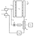
- Fig. 1 diagrammatically shows an embodiment of the invention in connection with a four-stroke turbo-supercharged diesel engine,
- Fig. 2 shows in more detail a device according to a first embodiment of the invention, and
- Fig. 3 shows a device according to a second embodiment of the invention.
- Fig. 1 shows diagrammatically a
combustion engine 1 of the piston engine type with cylinders arranged in a straight inline cylinder block. The engine is a four-stroke diesel engine adapted for a heavy vehicle such as a truck or a bus. Each cylinder is in its respective cylinder head in a conventional manner provided with at least one intake valve for supply of combustion air and at least one exhaust valve for discharge of exhaust gases from the combustion. Anintake channel 2 leads the intake air to the cylinders whereas anexhaust collector 3 leads the exhaust gases from the cylinders to the turbine T and subsequently to the exhaust pipe. - Further, a transfer channel 4 is arranged for recycling EGR gases from the exhaust side of the cylinders to their intake side. The transfer channel 4 debouches in the
intake channel 2 after a chargingair cooler 5 and before a manifold to the cylinders. An EGR control valve 6 is positioned in the transfer channel whereby the transfer may be disconnected and possibly controlled to a certain extent. - The transfer channel 4 debouches in a section of the intake channel wherein
venturi 9 is arranged in such a way that the flow of intake gases, which are charged by the compressor C, is modified so as to create a negative pressure at the passage of the venturi. This is because the air at the passage of a convex curved portion will be given an increased speed. According to the invention the EGR gases are led into said section in a portion in connection with the venturi where thus a negative pressure prevails. By shaping theventuri 9, in particular, i.a. with respect to curvature and length in the flow direction, it may be assured that an adequate negative pressure may be obtained so that a suitable amount of EGR gases may be transferred. S indicates a control computer for controlling the venturi as a response to parameter signals from the engine. - The
venturi 9 is shown in more detail in Fig. 2, where anadjustable wall portion 10 is shown in a position 10', where it is brought into thechannel 2 as much as possible and aposition 10", where it is brought out from thechannel 2 as much as possible with respect to arecess 12. The EGR transfer channel 4 debouches just about opposite that portion of theventuri 9 where the greatest negative pressure prevails. It is preferred that the channel 4 is arranged in a fixedwall 20 in the venturi but it may also debouch in the upper surface of the adjustable wall portion 10 (not shown). It is also preferred that the opening of the channel 4 in the venturi is directed in the flow direction in order to enhance transfer conditions. - 11 indicates a pivoting shaft whereby the
wall portion 9 may be adjusted for regulating the amount/portion of supplied EGR gases. In principle, the most inserted position 10'results in a greater negative pressure and a greater content of supplied EGR gases, whereas the brought outposition 10" results in smaller or possibly no amount of supplied EGR gases at all. - The section through A - A of the shown venturi is rectangular which means that the surface of the
wall portion 10, which is directed against the channel, is single-curved. The shape of this surface and its extension in the length direction and height direction is to be tested and dimensioned outgoing from engine data and desired EGR mixing conditions. - The
recess 12 thus serves for receiving thewall portion 10 in different retracted positions. It is preferred that theupstream portion 14 of the wall portion and the adjoiningsurface 13 of the recess in different retracted positions form a space having a section wherein a natural vortex V may be formed and be retained in operation. This gives an undisturbed operation without unwanted pressure fluctuations, which would otherwise occur if unstable vortices would be formed in this position. - Control of the amount of exhaust gases to be recycled is accomplished by the control system S (Fig. 1), which in a per see known manner communicates with sensors for sensing suitable engine parameters. The cooler 7 is arranged for cooling the recycled EGR gases. Fig. 2 (and 3) also shows a setting means 17, which is controlled by the control system S (Fig. 1) and may be provided with an electrically hydraulically or pneumatically operated motor.
- Fig. 3 shows an embodiment wherein a deformable membrane 15 is attached which provides a curve adjoining between the
wall portion 10 and the fixed wall 16. The membrane may for example be made of spring steel. - The shape of the
venturi 9 may thus vary depending on the present application. This also concerns the shape of the channel, but with the preferred embodiment, having a channel with a rectangular section, similar advantageous flow conditions are created over the width of thewall portion 10. The movement pattern of thewall portion 10 may be different if insertion into thechannel 2 is accomplished in any other way, for example by displacement. Larger portions of the wall may also be deformable besides only the membrane 15. - It is within the scope of the invention that only some of the cylinders of an engine contribute to EGR recycling, for example through one of the blocks of a V-engine.
- The invention has been described at the background of a supercharged four-stroke combustion engine, it is however, applicable in other kinds of combustion engines wherein similar problems or conditions prevail.
Claims (16)
- Method for exhaust gas recycling (EGR) in a combustion engine (1), wherein EGR gases are fed into the intake channel (2) of the engine so as to be led to the engine together with the intake air, and wherein EGR gases are supplied into a section of the intake channel where a venturi (9) is arranged for modifying the flow of the intake air, and where a reduced pressure prevails because of modified flow, wherein the EGR gases are led into the venturi, where a negative pressure prevails for feeding-in of the EGR gases,
characterized in that at least a portion of the wall (10) of the venturi (9) is adjusted for varying the cross section of the venturi and thereby for desired adjustment to prevailing operational conditions. - Method according to claim 1, characterized in that the adjustment is made by pivoting the adjustable wall portion (10).
- Method according to claim 1 or 2, characterized in that the EGR gases are led in through a channel (4) debouching in a fixed wall (20) of the venturi (9).
- Method according to claim 1 or 2,
characterized in that the EGR gases are led in through a channel (4) debouching in the adjustable wall portion (10). - Method according to any of the previous claims,
characterized in that the EGR gases are led in essentially in the flow direction (R) of the intake gases in the venturi (9). - Device for exhaust gas recycling (EGR) in a combustion engine (1) including means for feeding EGR-gases into the intake channel of the engine to be led to the engine together with the intake air, means for leading EGR gases into a section of the intake channel, where a venturi (9) included in the device is arranged for modifying the flow of the intake air, wherein a reduced pressure prevails because of modified flow, and wherein the EGR gases are led into the venturi, where in operation a negative pressure prevails,
characterized in that at least a portion of the wall (10) of the venturi (9) is adjustable for variation of the cross section of the venturi (9) and thereby for desired adjustment to prevailing operational conditions. - Device according to the claim 6, characterized in that at least one part of the adjustable wall portion (10) is pivotable.
- Device according to the claim 6 or 7,
characterized by a channel (4) debouching in a fixed wall (20) of the venturi (9) for leading in of the EGR gases. - Device according to the claim 6 or 7,
characterized by a channel (4) debouching in the adjustable wall portion (10) of the venturi for leading in of EGR gases. - Device according to any of the claims 6 - 9,
characterized by a recess (12) arranged sideways of the venturi (9), wherein the adjustable wall portion (10) is variably insertable. - Device according to claim 10, characterized in that an upstream portion (14) of the adjustable wall portion (10) is shaped so as to form a space together with an adjoining wall (13) of the recess (12) wherein, in operation, a natural vortex (V) of intake air may be created and remain in inserted positions of the insertable wall portion (10).
- Device according to claim 10, characterized by a deformable membrane (15), which is arranged to connect an upstream portion (14) of the adjustable wall portion (10) with the adjoining wall (13) of the recess (12) in a bridging manner.
- Device according to any of the claims 8 - 12,
characterized in that an opening of the channel (4) in the venturi (9) is directed essentially in the flow direction of the intake air. - Device according to any of the claims 6 - 13,
characterized in that it includes a setting means (17) including an electric, hydraulic or pneumatic motor for setting the adjustable wall portion. - Device according to any of the claims 6 - 14,
characterized in that the cross section of the venturi (9) is essentially rectangular with adjustable height. - Supercharged diesel engine, characterized in that it includes a device according to any of the claims 6 - 15.
Applications Claiming Priority (3)
| Application Number | Priority Date | Filing Date | Title |
|---|---|---|---|
| SE0001896A SE521968C2 (en) | 2000-05-22 | 2000-05-22 | Method and apparatus for exhaust gas recirculation in an internal combustion engine and such engine |
| SE0001896 | 2000-05-22 | ||
| PCT/SE2001/001083 WO2001090559A1 (en) | 2000-05-22 | 2001-05-16 | Method and device for exhaust recycling and supercharged diesel engine |
Publications (2)
| Publication Number | Publication Date |
|---|---|
| EP1290327A1 EP1290327A1 (en) | 2003-03-12 |
| EP1290327B1 true EP1290327B1 (en) | 2007-10-31 |
Family
ID=20279778
Family Applications (1)
| Application Number | Title | Priority Date | Filing Date |
|---|---|---|---|
| EP01934744A Expired - Lifetime EP1290327B1 (en) | 2000-05-22 | 2001-05-16 | Method and device for exhaust recycling and supercharged diesel engine |
Country Status (7)
| Country | Link |
|---|---|
| US (1) | US7040305B2 (en) |
| EP (1) | EP1290327B1 (en) |
| JP (1) | JP2003534487A (en) |
| AU (1) | AU2001260898A1 (en) |
| DE (1) | DE60131161T2 (en) |
| SE (1) | SE521968C2 (en) |
| WO (1) | WO2001090559A1 (en) |
Families Citing this family (15)
| Publication number | Priority date | Publication date | Assignee | Title |
|---|---|---|---|---|
| US6895752B1 (en) * | 2003-10-31 | 2005-05-24 | Caterpillar Inc | Method and apparatus for exhaust gas recirculation cooling using a vortex tube to cool recirculated exhaust gases |
| US7261096B2 (en) * | 2005-11-17 | 2007-08-28 | Haldex Hydraulics Ab | Movable sleeve exhaust gas recirculation system |
| DE102006009153A1 (en) * | 2006-02-24 | 2007-08-30 | Mahle International Gmbh | Exhaust gas recirculation device |
| JP4827757B2 (en) * | 2007-02-05 | 2011-11-30 | Udトラックス株式会社 | Multi-cylinder engine |
| DE102007045623B4 (en) * | 2007-09-24 | 2009-07-23 | Knorr-Bremse Systeme für Nutzfahrzeuge GmbH | Method and apparatus for improving exhaust gas recirculation of an internal combustion engine |
| WO2010083151A2 (en) * | 2009-01-13 | 2010-07-22 | Avl North America Inc. | Ejector type egr mixer |
| CA2881631A1 (en) | 2012-08-14 | 2014-02-20 | Mack Trucks, Inc. | Vacuum insulated venturi meter for an exhaust gas recirculation apparatus |
| US10316803B2 (en) | 2017-09-25 | 2019-06-11 | Woodward, Inc. | Passive pumping for recirculating exhaust gas |
| US10995705B2 (en) | 2019-02-07 | 2021-05-04 | Woodward, Inc. | Modular exhaust gas recirculation system |
| CN110778428B (en) * | 2019-11-28 | 2021-10-08 | 一汽解放汽车有限公司 | A High Efficiency EGR Introduction Hybrid System |
| CN213175878U (en) | 2020-01-08 | 2021-05-11 | 伍德沃德有限公司 | Exhaust Gas Recirculation Mixers and Engine Systems |
| US11268427B2 (en) * | 2020-01-08 | 2022-03-08 | Cnh Industrial America Llc | Aspiration systems for work vehicles including exhaust tubes having airflow area modifiers |
| US11519767B2 (en) * | 2020-09-08 | 2022-12-06 | Saudi Arabian Oil Company | Determining fluid parameters |
| US11215132B1 (en) | 2020-12-15 | 2022-01-04 | Woodward, Inc. | Controlling an internal combustion engine system |
| US11174809B1 (en) | 2020-12-15 | 2021-11-16 | Woodward, Inc. | Controlling an internal combustion engine system |
Family Cites Families (8)
| Publication number | Priority date | Publication date | Assignee | Title |
|---|---|---|---|---|
| JPS5219818A (en) * | 1975-08-08 | 1977-02-15 | Hitachi Ltd | Mixed gas suppiying device for internal combustion engine |
| JPS5338821A (en) * | 1976-09-21 | 1978-04-10 | Nissan Motor Co Ltd | Controller for exhaust reflux |
| JPS5359134A (en) * | 1976-11-05 | 1978-05-27 | Mazda Motor Corp | Exhaust gas reflux apparatus f engine |
| EP0853266B1 (en) * | 1991-03-15 | 2002-01-30 | PALMER, David W. | Process-chamber flow control system |
| JP2548779Y2 (en) * | 1992-09-18 | 1997-09-24 | 日産ディーゼル工業株式会社 | EGR device for turbocharged engine |
| US5611204A (en) * | 1993-11-12 | 1997-03-18 | Cummins Engine Company, Inc. | EGR and blow-by flow system for highly turbocharged diesel engines |
| US5611203A (en) * | 1994-12-12 | 1997-03-18 | Cummins Engine Company, Inc. | Ejector pump enhanced high pressure EGR system |
| JPH10318046A (en) * | 1997-05-15 | 1998-12-02 | Ishikawajima Harima Heavy Ind Co Ltd | Exhaust recirculation system for turbocharged engine |
-
2000
- 2000-05-22 SE SE0001896A patent/SE521968C2/en not_active IP Right Cessation
-
2001
- 2001-05-16 WO PCT/SE2001/001083 patent/WO2001090559A1/en not_active Ceased
- 2001-05-16 DE DE60131161T patent/DE60131161T2/en not_active Expired - Lifetime
- 2001-05-16 EP EP01934744A patent/EP1290327B1/en not_active Expired - Lifetime
- 2001-05-16 AU AU2001260898A patent/AU2001260898A1/en not_active Abandoned
- 2001-05-16 US US10/296,268 patent/US7040305B2/en not_active Expired - Lifetime
- 2001-05-16 JP JP2001586728A patent/JP2003534487A/en active Pending
Also Published As
| Publication number | Publication date |
|---|---|
| SE0001896L (en) | 2001-11-23 |
| WO2001090559A1 (en) | 2001-11-29 |
| US7040305B2 (en) | 2006-05-09 |
| JP2003534487A (en) | 2003-11-18 |
| US20040007220A1 (en) | 2004-01-15 |
| SE0001896D0 (en) | 2000-05-22 |
| DE60131161T2 (en) | 2008-08-07 |
| EP1290327A1 (en) | 2003-03-12 |
| SE521968C2 (en) | 2003-12-23 |
| DE60131161D1 (en) | 2007-12-13 |
| AU2001260898A1 (en) | 2001-12-03 |
Similar Documents
| Publication | Publication Date | Title |
|---|---|---|
| EP1290328B1 (en) | Method and device for exhaust recycling and supercharged diesel engine | |
| US7040305B2 (en) | Method and device for exhaust recycling and supercharged diesel engine | |
| US6209530B1 (en) | Control system for exhaust gas recirculation system | |
| US6742506B1 (en) | Combustion engine having exhaust gas recirculation | |
| EP0489263B1 (en) | Exhaust gas recirculation system for an internal combustion engine | |
| US4930315A (en) | Turbo-charger engine system | |
| US6672061B2 (en) | Internal combustion engine with an exhaust turbocharger and an exhaust-gas recirculation device | |
| EP1178192A3 (en) | Apparatus for controlling supercharging pressure in internal combustion engine | |
| US20070180824A1 (en) | Control of supercharged engine with variable geometry turbocharger and electric supercharger | |
| EP4088016B1 (en) | Passive pumping for recirculating exhaust gas | |
| EP1676995A1 (en) | Device for imparting a movement of rotation to the air flow fed to a turbo-charged internal combustion engine | |
| GB2242226A (en) | I.C. engine intake baffle | |
| US4484549A (en) | 4-Cycle internal combustion engine | |
| GB1598173A (en) | Internal combustion engine intake systems | |
| US6851415B2 (en) | System for exhaust/crankcase gas recirculation | |
| WO1999060259A1 (en) | Arrangement for exhaust gas recirculation and internal combustion engine | |
| US5582156A (en) | Two-cycle internal combustion engine with reduced unburned hydrocarbons in the exhaust gas and adjustable spark gap electrodes | |
| US4257374A (en) | Method of controlling internal combustion | |
| JPH0341055Y2 (en) | ||
| WO2001090561A1 (en) | Method and device for exhaust recycling and supercharged diesel engine | |
| JPS60261928A (en) | Engine provided with supercharger | |
| JPS63297725A (en) | Engine with turbocharger | |
| JPH066902B2 (en) | Engine supercharger | |
| JPH04132834A (en) | Air suction device of engine | |
| JPS626088B2 (en) |
Legal Events
| Date | Code | Title | Description |
|---|---|---|---|
| PUAI | Public reference made under article 153(3) epc to a published international application that has entered the european phase |
Free format text: ORIGINAL CODE: 0009012 |
|
| 17P | Request for examination filed |
Effective date: 20021223 |
|
| AK | Designated contracting states |
Designated state(s): AT BE CH CY DE DK ES FI FR GB GR IE IT LI LU MC NL PT SE TR Kind code of ref document: A1 Designated state(s): AT BE CH CY DE DK ES FI FR GB GR IE IT LI LU MC NL PT SE TR |
|
| AX | Request for extension of the european patent |
Extension state: AL LT LV MK RO SI |
|
| RBV | Designated contracting states (corrected) |
Designated state(s): DE FR GB IT |
|
| GRAP | Despatch of communication of intention to grant a patent |
Free format text: ORIGINAL CODE: EPIDOSNIGR1 |
|
| GRAS | Grant fee paid |
Free format text: ORIGINAL CODE: EPIDOSNIGR3 |
|
| GRAA | (expected) grant |
Free format text: ORIGINAL CODE: 0009210 |
|
| AK | Designated contracting states |
Kind code of ref document: B1 Designated state(s): DE FR GB IT |
|
| REG | Reference to a national code |
Ref country code: GB Ref legal event code: FG4D |
|
| REF | Corresponds to: |
Ref document number: 60131161 Country of ref document: DE Date of ref document: 20071213 Kind code of ref document: P |
|
| EN | Fr: translation not filed | ||
| PLBE | No opposition filed within time limit |
Free format text: ORIGINAL CODE: 0009261 |
|
| STAA | Information on the status of an ep patent application or granted ep patent |
Free format text: STATUS: NO OPPOSITION FILED WITHIN TIME LIMIT |
|
| 26N | No opposition filed |
Effective date: 20080801 |
|
| PG25 | Lapsed in a contracting state [announced via postgrant information from national office to epo] |
Ref country code: FR Free format text: LAPSE BECAUSE OF FAILURE TO SUBMIT A TRANSLATION OF THE DESCRIPTION OR TO PAY THE FEE WITHIN THE PRESCRIBED TIME-LIMIT Effective date: 20080704 |
|
| GBPC | Gb: european patent ceased through non-payment of renewal fee |
Effective date: 20080516 |
|
| PG25 | Lapsed in a contracting state [announced via postgrant information from national office to epo] |
Ref country code: GB Free format text: LAPSE BECAUSE OF NON-PAYMENT OF DUE FEES Effective date: 20080516 |
|
| PG25 | Lapsed in a contracting state [announced via postgrant information from national office to epo] |
Ref country code: IT Free format text: LAPSE BECAUSE OF NON-PAYMENT OF DUE FEES Effective date: 20080531 |
|
| PGFP | Annual fee paid to national office [announced via postgrant information from national office to epo] |
Ref country code: DE Payment date: 20200506 Year of fee payment: 20 |
|
| REG | Reference to a national code |
Ref country code: DE Ref legal event code: R071 Ref document number: 60131161 Country of ref document: DE |