EP1289327A2 - Communication channel setting method, communication controller, and radio communication system - Google Patents
Communication channel setting method, communication controller, and radio communication system Download PDFInfo
- Publication number
- EP1289327A2 EP1289327A2 EP02018260A EP02018260A EP1289327A2 EP 1289327 A2 EP1289327 A2 EP 1289327A2 EP 02018260 A EP02018260 A EP 02018260A EP 02018260 A EP02018260 A EP 02018260A EP 1289327 A2 EP1289327 A2 EP 1289327A2
- Authority
- EP
- European Patent Office
- Prior art keywords
- channel
- reception
- transmission
- communication
- frequency
- Prior art date
- Legal status (The legal status is an assumption and is not a legal conclusion. Google has not performed a legal analysis and makes no representation as to the accuracy of the status listed.)
- Withdrawn
Links
Images






Classifications
-
- H—ELECTRICITY
- H04—ELECTRIC COMMUNICATION TECHNIQUE
- H04W—WIRELESS COMMUNICATION NETWORKS
- H04W16/00—Network planning, e.g. coverage or traffic planning tools; Network deployment, e.g. resource partitioning or cells structures
- H04W16/02—Resource partitioning among network components, e.g. reuse partitioning
- H04W16/10—Dynamic resource partitioning
-
- H—ELECTRICITY
- H04—ELECTRIC COMMUNICATION TECHNIQUE
- H04J—MULTIPLEX COMMUNICATION
- H04J1/00—Frequency-division multiplex systems
- H04J1/02—Details
- H04J1/12—Arrangements for reducing cross-talk between channels
-
- H—ELECTRICITY
- H04—ELECTRIC COMMUNICATION TECHNIQUE
- H04W—WIRELESS COMMUNICATION NETWORKS
- H04W24/00—Supervisory, monitoring or testing arrangements
- H04W24/10—Scheduling measurement reports ; Arrangements for measurement reports
-
- H—ELECTRICITY
- H04—ELECTRIC COMMUNICATION TECHNIQUE
- H04W—WIRELESS COMMUNICATION NETWORKS
- H04W72/00—Local resource management
- H04W72/02—Selection of wireless resources by user or terminal
-
- H—ELECTRICITY
- H04—ELECTRIC COMMUNICATION TECHNIQUE
- H04W—WIRELESS COMMUNICATION NETWORKS
- H04W92/00—Interfaces specially adapted for wireless communication networks
- H04W92/16—Interfaces between hierarchically similar devices
- H04W92/20—Interfaces between hierarchically similar devices between access points
Definitions
- the present invention relates to a communication channel setting method, a communication controller, and a radio communication system, which set a communication channel between radio base stations.
- the frequency band used for radio lines is divided, for example, into two frequency bands, i.e. a low frequency group and a high frequency group with a guard band which is set in between. And, it is arranged that a frequency band is assigned to a radio line for transmission (transmission line) and to a radio line for reception (reception line) by paired channels which correspond to the low frequency group and the high frequency group, respectively.
- the symbols A to E and the symbols A' to E' each represent a radio line, and each arrow represents a band which is assigned to each radio line.
- the A and A', B and B', etc. each represent paired channels in the low frequency group and the high frequency group which are used for the transmission line and for the reception line, respectively.
- the bandwidth of the frequency band (the bandwidth of the channel) which is assigned to each radio line was made fixed regardless of the amount of information which was forwarded to the radio line.
- a communication channel setting method for setting a communication channel used for communication between radio base stations comprising the steps of: (A) measuring a noise level in a transmission band which can be used for communication from a first radio base station to a second radio base station; (B) selecting a transmission channel in the transmission band in which the measured noise level is lower than a prescribed threshold; (C) measuring a noise level in a reception band which can be used for communication from said second radio base station to said first radio base station; (D) selecting a reception channel in the reception band in which the measured noise level is lower than a prescribed threshold; and (E) determining said transmission channel and said reception channel independently.
- This communication channel setting method measures a noise level in a transmission band which can be used for communication from a first radio base station to a second radio base station, selects a transmission channel in the transmission band in which the measured noise level is lower than a prescribed threshold, measures a noise level in a reception band which can be used for communication from said second radio base station to said first radio base station, and selects a reception channel in the reception band in which the measured noise level is lower than a prescribed threshold.
- a radio communication system for performing communication between radio base stations, comprising: a first noise level measuring unit configured to measure a noise level in a transmission band which can be used for communication performed from a first radio base station to a second radio base station; a transmission channel selector for selecting a transmission channel in the transmission band in which the measured noise level is lower than a prescribed threshold; a second noise level measuring unit configured to measure a noise level in a reception band which can be used for communication from said second radio base station to said first radio base station; a reception channel selector for selecting a reception channel in the reception band in which the measured noise level is lower than a prescribed threshold; and a communication channel setting unit configured to set the transmission channel selected by the transmission channel selector and the reception channel selected by the reception channel selector as communication channels between said radio base stations, whereby the selection of the transmission channel by said transmission channel selector and the selection of the reception channel by said reception channel selector are independently determined.
- the present invention can be applied to a radio communication system that performs communication between base stations providing communication services with respect to, for example, portable terminal devices.
- This radio communication system is equipped with a plurality of base stations 100, 200, 300, 400, 500, and 600, for example, as illustrated in Fig. 3.
- Each of these base stations 100, 200, etc. are deployed for each prescribed cell provided within a service providing area providing communication services, for example, to portable terminal devices.
- the respective base stations 100, 200, etc. are arranged to be able to perform communications by using their corresponding radio lines A, A', B, B', etc.
- Corresponding pairs of radio lines A and A', B and B', etc. indicate a transmission line and a corresponding reception line, respectively for one of the base stations.
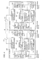
- the base station 100 includes an antenna 101, a transmission / reception separating part 102, a receiving part 103, a demodulating part 104, a separating part 105, an interference wave data measuring part 106, a frequency band controlling part 107, a transmission information volume measuring part 108, a transmitting part 109, a modulating part 110, and a multiplexing part 111.
- the antenna 101 performs transmission / reception of the radio waves.
- the transmission / reception separating part 102 separates a transmission signal and a reception signal.
- the receiving part 103 performs the adjustment of the amplitude of the reception signal, etc.
- the demodulating part 104 reproduces a baseband signal from the reception signal.
- the separating part 105 separates the reproduced baseband signal into an information signal and a control signal.
- the interference wave data measuring part 106 measures the frequency and the power of the interference wave.
- the frequency band controlling part 107 executes the control of the frequency for the communication channel, etc.
- the transmission information volume measuring part 108 measures the amount of information that is to be forwarded.
- the transmitting part 109 executes processes such as the adjustment of the amplitude of the transmission signal, the suppression of spurious components, etc.
- the modulating part 110 forms a transmission signal, supplied to the transmitting part 109, according to the information to be forwarded, etc.
- the multiplexing part 111 multiplexes information supplied by the frequency band controlling part 107 that indicates the frequency, bandwidth, etc. of the communication channel, the output signal for measurement from the interference wave data measuring part 106, and an information signal supplied by an outside device, etc.
- a base station 200 which performs communication with the base station 100 includes, similar to the base station 100, an antenna 201, a transmission / reception separating part 202, a receiving part 203, a demodulating part 204, a separating part 205, an interference wave data measuring part 206, a frequency band controlling part 207, a transmission information volume measuring part 208, a transmitting part 209, a modulating part 210, and a multiplexing part 211.
- the antenna 201 performs transmission / reception of the radio waves.
- the transmission / reception separating part 202 separates a transmission signal and a reception signal.
- the receiving part 203 performs the adjustment of the amplitude of the reception signal, etc.
- the demodulating part 204 reproduces a baseband signal from the reception signal.
- the separating part 205 separates the reproduced baseband signal into an information signal and a control signal.
- the interference wave data measuring part 206 measures the frequency and received power of the interference wave.
- the frequency band controlling part 207 executes the control of the frequency for the communication channel, etc.
- the transmission information volume measuring part 208 measures the amount of information that is to be forwarded.
- the transmitting part 209 executes processes such as the adjustment of the amplitude of the transmission signal, suppression of spurious components, etc.
- the modulating part 210 forms a transmission signal, supplied to the transmitting part 209, according to the information to be forwarded, etc.
- the multiplexing part 211 multiplexes information supplied by the frequency band controlling part 207 that indicates the frequency, bandwidth, etc. of the communication channel, the output signal for measurement from the interference wave data measuring part 206, and an information signal supplied by an outside device, etc.
- a radio line used for transmission from the base station 100 to the base station 200 (referred to as “the transmission line” for convenience of explanation) and a radio line used for transmission from the base station 200 to the base station 100 (referred to as “the reception line” for convenience of explanation) are set as the communication channels according to the prescribed procedures carried out between the frequency band controlling part 107 and the frequency band controlling part 207. Thereafter, communications start between the both base stations.
- the signal which the base station 100 receives from the base station 200 via the antenna 101 is supplied to the receiving part 103 via the transmission / reception separating part 102.
- the reception signal of which the receiving part 103 performes adjustment of the amplitude, etc. is supplied to the demodulating part 104, and then the signal is demodulated, thereby reproducing a baseband signal.
- the baseband signal thus reproduced is supplied to the separating part 105 and the signal is separated into an information signal from the base station 200 to the base station 100, a control signal that contains information indicating the frequency, etc. of the radio line (the reception line) from the base station 200 to the base station 100, and information indicating the power, etc. of the interference wave received by the antenna 201.
- the control signal is supplied to the frequency band controlling part 107 while the information signal is supplied to an outside device.
- the interference wave data measuring part 106 measures the frequency and received power of the interference wave in the signal received by the receiving part 103 and information indicating these measured result is supplied to the multiplexing part 111.
- the frequency band controlling part 107 produces information such as the frequency of the transmission line and supplies it to the multiplexing part 111.
- an information signal, etc. from an outside device is supplied to the multiplexing part 111.
- the transmission information volume measuring part 108 measures the amount of information multiplexed by the multiplexing part 111 and supplies the measured results to the frequency band controlling part 107.
- the frequency band controlling part 107 controls the frequency and bandwidth of the transmission signal formed by the modulating part 110, according to the information indicating the frequency of the communication channel, etc. which is supplied by the separating part 105, the amount of information to be forwarded which is supplied by the transmission information volume measuring part 108, and the information indicating the power of the interference wave received by the antenna 201 and supplied by the separating part 105. Specifically, for example, the frequency band controlling part 107 sets the transmission line to a frequency band with an interference wave of less power than a prescribed threshold (the prescribed received power of the interference wave) and which is different to a frequency band for the radio line (the reception line) used from the base station 200 to the base station 100.
- a prescribed threshold the prescribed received power of the interference wave
- This prescribed received power of the interference wave is set, for example, according to the communication requirements for this radio communication system (e.g. the CN ratio [Carrier to Noise Ratio, the ratio of carrier to noise]; the SIR [Signal to Interference Ratio, the ratio of signal to interference], QoS [Quality of Service]; and so on).
- the modulating part 110 forms a transmission signal conforming to the information multiplexed by the multiplexing part 111, according to the control by the frequency band controlling part 107, and the thus-produced transmission signal is supplied to the transmitting part 109.
- the transmitting part 109 performs the adjustment of the amplitude of the supplied transmission signal and supplies the adjusted signal to the transmission / reception separating part 102.
- the transmission signal that has been supplied to the transmission / reception separating part 102 is supplied to the antenna 101, and then is transmitted to the base station 200 via the antenna 101.
- the reception signal received via the antenna 201 is supplied to the receiving part 203 via the transmission /reception separating part 202.
- the reception signal is demodulated by the demodulating part 204, thereby reproducing a baseband signal.
- the separating part 205 the baseband signal thus reproduced is separated into an information signal and a control signal, which are supplied to the frequency band controlling part 207 and to an outside device, respectively.
- the frequency band controlling part 207 produces information such as the frequency of the reception line and supplies it to the multiplexing part 211.
- information indicating the measured results of the interference wave data measuring part 206 and an information signal from an outside device, etc. are supplied to the multiplexing part 211.
- the frequency band controlling part 207 controls the frequency and bandwidth of the transmission signal formed by modulating part 210, according to the information indicating the frequency of the communication channel, etc. which is supplied by the separating part 205, and the amount of information to be forwarded which is supplied by the transmission information volume measuring part 208, etc.
- the modulating part 210 forms a transmission signal conforming to the information multiplexed by the multiplexing part 211, according to the control by the frequency band controlling part 207, and the thus-produced transmission signal is supplied to the transmitting part 209.
- the transmitting part 209 performs the adjustment of the amplitude of the supplied transmission signal and supplies the adjusted signal to the antenna 201 via the transmission /reception separating part 202.
- the antenna 201 is driven by the thus-supplied transmission signal, which is transmitted to the base station 100.
- the frequency of the transmission line and that of the reception line are controlled according to the frequency, power, etc. of the interference wave.
- the bandwidths for the transmission line and reception line are controlled according to the amount of information to be forwarded (more exactly the amount of information per unit amount of time).
- step S1 to step S6 illustrate the process in a base station (transmission side base station) seeking to begin communication with another base station while the steps of processing from step S11 to step S12 illustrate the process from the reception side base station (reception side base station).
- the frequency band controlling part 107 of the transmission side base station (e.g. the base station 100) first transmits information requesting the setting of a radio line to the reception side base station (e.g. the base station 200) (S1), and calculates a required bandwidth based on the amount of transmission information that was measured by the transmission information volume measuring part 108 (S2).
- the reception side base station when receiving the request for setting the radio line (S11), transmits to the transmission side base station information indicating the frequency, bandwidth, power, etc. of the interference wave, which has been measured by the interference wave data measuring part 206, and information indicating the frequency, bandwidth, etc. (frequency band information) which the reception side base station has assigned for the radio line (the reception line at the base station 100) for transmission from the reception side base station (S12).
- the transmission side base station information indicating the frequency, bandwidth, power, etc. of the interference wave, which has been measured by the interference wave data measuring part 206, and information indicating the frequency, bandwidth, etc. (frequency band information) which the reception side base station has assigned for the radio line (the reception line at the base station 100) for transmission from the reception side base station (S12).
- the frequency band controlling part 107 of the transmission side base station determines the frequency and bandwidth assignable for the transmission line to the reception base station based on the received information indicating the frequency, band, power, etc. of the interference wave at the reception side base station (S4). Specifically, the frequency band controlling part 107 determines, for example, the frequency and bandwidth at which the power of the interference wave is smaller than a prescribed threshold, and which are treated as the frequency and bandwidth assignable.
- the frequency band controlling part 107 selects the frequency and bandwidth for the transmission line in view of the determined assignable frequency / bandwidth, and the frequency / bandwidth applicable to the reception line (S5).
- the transmission side base station After the frequency and bandwidth for the transmission line and reception line are determined in the above-described way, the transmission side base station starts transmission using these lines as the communication channels (S6). Then, the assignment processing for the communication channels at the transmission side base station is completed.
- the radio line e.g. the transmission line at the transmission side base station
- the frequency band according to the amount of information to be forwarded (exactly the amount of information per unit amount of time), the power and frequency of the interference wave at the opposite side base station, and the frequency and bandwidth of the radio line used in the opposite direction (the reception line at the transmission side base station).
- the frequency and bandwidth for each of the transmission and reception lines can be set independently. Therefore, available frequencies can be properly utilized for the transmission and reception lines with the result that it is possible to contribute to enhancing frequency utilization efficiency.
- this radio communication system it is possible to autonomously set the communication channels based on information such as the frequency, bandwidth, power, etc. of the interference wave at the base station at which each base station performs communication and information such as the frequency, bandwidth, etc. of the radio line which the opposite side base station has set. Therefore, for example, centralized management of the communication channel between respective base stations, which is applicable to controlling of communication channels between the mobile station and the base station, is not required. This can contribute to decreasing the control load of the entire system.
- the above-described assignment processing for the communication channel can also be applied, for example, to changing the communication channel if the amount of information to be forwarded has changed, in addition to setting of the communication channel at the start of communication.
- the frequency and bandwidth (hereinafter referred to simply as "the frequency band" ) for the transmission line at the step S5 in Fig. 5 are selected based on the assignable frequency band for the transmission line which can be determined by the frequency, bandwidth and the power of the interference wave, the bandwidth of the transmission line, and the frequency band of the reception line.
- the assignable frequency band for the transmission line which can be determined by the frequency, bandwidth and the power of the interference wave, the bandwidth of the transmission line, and the frequency band of the reception line.
- the frequency band controlling part 107 selects a frequency band for the transmission line distant from a prescribed frequency interval from the frequency band for the reception line.
- the frequency band controlling part 107 selects a frequency band of the transmission line, which minimizes a frequency interval to the frequency band for the reception line .
- the frequency band for the transmission line and that for the reception line become vicinal to each other, with the result that frequency utilization efficiency is enhanced. Accordingly, for example, it is possible to decrease the frequency band required for the entire radio communication system.
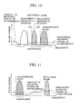
- the frequency band whose frequency is lower than the reception line is selected as the transmission line as illustrated in Fig. 9 for example, or the frequency band whose frequency is higher than the reception line is selected as the transmission line as illustrated in Fig. 10 for example.
- the frequency band whose frequency is low or high is selected depends upon the location of the base station and the circumstances of the other radio communication system using adjacent frequencies, etc. Alternatively, the selection of the frequency band may be actively changed according to the circumstances.
- the frequency band controlling part 107 selects the frequency band for the transmission line whose frequency is the lowest of the assignable frequency bands.
- the frequency band for the reception line is set to the lowest frequency of the assignable frequency band for the transmission line
- the frequency band having the prescribed frequency interval from the frequency band for the reception line is selected as the frequency band for the transmission line.
- the frequency band whose frequency is the lowest is selected as the frequency band for each radio line, resulting in efficient frequency assignment as illustrated in Fig. 13 for example. This can contribute to enhancing frequency utilization efficiency.
- the frequency band controlling part 107 selects the frequency band for the transmission line whose frequency is the highest of the assignable frequency bands.
- the frequency band whose frequency is the highest is selected as the frequency band for each radio line, resulting in efficient frequency assignment as illustrated in Fig. 16 for example. This can contribute to enhancing frequency utilization efficiency.
- the present invention has been applied to communications in a network of base stations providing communications services to portable terminal devices is explained, the technical idea of the present invention is not limited to such embodiment.
- the present invention can also be applied to the communications between a base station and a portable terminal device.
- the communication channel setting method of the present invention comprises measuring noise levels in a transmission band which can be used for communication from a first base station to a second radio base station, selecting a transmission channel in the transmission band in which the measured noise level is lower than a prescribed threshold, measuring noise levels in a reception band which can be used for communication from the second radio base station to the first base station, and selecting a reception channel in the reception band in which the measured noise level is lower than a prescribed threshold independent of the transmission channel.
- the present invention can contribute to enhancing channel utilization efficiency.
- the bandwidth for the transmission channel and the bandwidth for the reception channel are set according to the transmission rate of data to be forwarded. This enables the necessary and minimum band to be used and it contributes to enhancing frequency utilization efficiency.
Landscapes
- Engineering & Computer Science (AREA)
- Computer Networks & Wireless Communication (AREA)
- Signal Processing (AREA)
- Mobile Radio Communication Systems (AREA)
- Small-Scale Networks (AREA)
Abstract
Description
Claims (16)
- A communication channel setting method for setting a communication channel used for communication between radio base stations, comprising the steps of:(A) measuring a noise level in a transmission band which can be used for communication from a first radio base station to a second radio base station;(B) selecting a transmission channel in the transmission band in which the measured noise level is lower than a prescribed threshold;(C) measuring a noise level in a reception band which can be used for communication from said second radio base station to said first radio base station;(D) selecting a reception channel in the reception band in which the measured noise level is lower than a prescribed threshold; and(E) determining said transmission channel and said reception channel independently.
- A communication channel setting method according to claim 1, wherein the step (B) comprises the selection of said transmission channel by giving priority to a channel, distant by more than a prescribed frequency interval from said reception channel and having a frequency nearest to the frequency band of said reception channel, from among channels lower in said measured noise level than a prescribed threshold.
- A communication channel setting method according to claim 1, wherein the step (D) comprises the selection of said reception channel by giving priority to a channel, distant by more than a prescribed frequency interval from said transmission channel and having a frequency nearest to the frequency band of said transmission channel, from among channels lower in said measured noise level than a prescribed threshold.
- A communication channel setting method according to claim 1, wherein the step (B) comprises the selection of said transmission channel by giving priority to a channel, distant by more than a prescribed frequency interval from said reception channel and having the lowest frequency in said transmission band, from among channels lower in said measured noise level than a prescribed threshold.
- A communication channel setting method according to claim 1, wherein the step (D) comprises the selection of said reception channel by giving priority to a channel, distant by more than a prescribed frequency interval from said transmission channel and having the lowest frequency in said reception band, from among channels lower in said measured noise level than a prescribed threshold.
- A communication channel setting method according to claim 1, wherein the step (B) comprises the selection of said transmission channel by giving priority to a channel, distant by more than a prescribed frequency interval from said reception channel and having the highest frequency in said transmission band, from among channels lower in said measured noise level than a prescribed threshold.
- A communication channel setting method according to claim 1, wherein the step (D) comprises the selection of said reception channel by giving priority to a channel, distant by more than a prescribed frequency interval from said transmission channel and having the highest frequency in said reception band, from among channels lower in said measured noise level than a prescribed threshold.
- A communication channel setting method according to claim 1, wherein, the bandwidth of said transmission channel or the bandwidth of said reception channel is set according to the transmission rate of data which is to be forwarded.
- A communication controller for setting a communication channel used for communication between radio base stations, comprising:a first noise level measuring unit configured to measure a noise level in a transmission band which can be used for communication from a first radio base station to a second radio base station;a transmission channel selector for selecting a transmission channel in the transmission band in which the measured noise level is lower than a prescribed threshold;a second noise level measuring unit configured to measure a noise level in a reception band which can be used for communication from said second radio base station to said first radio base station; anda reception channel selector for selecting a reception channel in the reception band in which the measured noise level is lower than a prescribed threshold, wherebythe selection of the channel for transmission by said transmission channel selector and the selection of the channel for reception by said reception channel selector are independently determined.
- A communication controller according to claim 9, wherein, said transmission channel selector comprises the selection of said transmission channel by giving priority to a channel, distant by more than a prescribed frequency interval from said reception channel and having a frequency nearest to the frequency band of said reception channel, from among channels lower in said measured noise level than a prescribed threshold.
- A communication controller according to claim 9, wherein, said reception channel selector comprises the selection of said reception channel by giving priority to a channel, distant by more than a prescribed frequency interval from said transmission channel and having a frequency nearest to the frequency band of said transmission channel, from among channels lower in said measured noise level than a prescribed threshold.
- A communication controller according to claim 9, further comprising a bandwidth setting unit configured to set the bandwidth of said transmission channel or the bandwidth of said reception channel according to the transmission rate of data which is to be forwarded.
- A radio communication system for performing communication between radio base stations, comprising:a first noise level measuring unit configured to measure a noise level in a transmission band which can be used for communication performed from a first radio base station to a second radio base station;a transmission channel selector for selecting a transmission channel in the transmission band in which the measured noise level is lower than a prescribed threshold;a second noise level measuring unit configured to measure a noise level in a reception band which can be used for communication from said second radio base station to said first radio base station;a reception channel selector for selecting a reception channel in the reception band in which the measured noise level is lower than a prescribed threshold; anda communication channel setting unit configured to set the transmission channel selected by the transmission channel selector and the reception channel selected by the reception channel selector as communication channels between said radio base stations, wherebythe selection of the transmission channel by said transmission channel selector and the selection of the reception channel by said reception channel selector are independently determined.
- A radio communication system according to claim 13, wherein, said transmission channel selector comprises the selection of said transmission channel by giving priority to a channel, distant by more than a prescribed frequency interval from said reception channel and having a frequency nearest to the frequency band of said reception channel, from among channels lower in said measured noise level than a prescribed threshold.
- A radio communication system according to claim 13, wherein, said reception channel selector comprises the selection of said reception channel by giving priority to a channel, distant by more than a prescribed frequency interval from said transmission channel and having a frequency nearest to the frequency band of said transmission channel, from among channels lower in said measured noise level than a prescribed threshold.
- A radio communication system according to claim 13, further comprising a bandwidth setting unit configured to set the bandwidth of said transmission channel or the bandwidth of said reception channel according to the transmission rate of data which is to be forwarded.
Applications Claiming Priority (2)
| Application Number | Priority Date | Filing Date | Title |
|---|---|---|---|
| JP2001258586 | 2001-08-28 | ||
| JP2001258586A JP2003070056A (en) | 2001-08-28 | 2001-08-28 | Communication channel setting method, communication control device, and wireless communication system |
Publications (2)
| Publication Number | Publication Date |
|---|---|
| EP1289327A2 true EP1289327A2 (en) | 2003-03-05 |
| EP1289327A3 EP1289327A3 (en) | 2005-12-28 |
Family
ID=19086079
Family Applications (1)
| Application Number | Title | Priority Date | Filing Date |
|---|---|---|---|
| EP02018260A Withdrawn EP1289327A3 (en) | 2001-08-28 | 2002-08-22 | Communication channel setting method, communication controller, and radio communication system |
Country Status (6)
| Country | Link |
|---|---|
| US (1) | US6985737B2 (en) |
| EP (1) | EP1289327A3 (en) |
| JP (1) | JP2003070056A (en) |
| KR (1) | KR100621953B1 (en) |
| CN (1) | CN1182742C (en) |
| SG (1) | SG114562A1 (en) |
Families Citing this family (23)
| Publication number | Priority date | Publication date | Assignee | Title |
|---|---|---|---|---|
| US20070009123A1 (en) * | 2003-04-30 | 2007-01-11 | Stefan Aschoff | Remote control unit for a hearing aid |
| JP2005341432A (en) * | 2004-05-28 | 2005-12-08 | Ntt Docomo Inc | Frequency selection apparatus, mobile communication system, and multiband control method |
| JP4522753B2 (en) * | 2004-06-11 | 2010-08-11 | 株式会社エヌ・ティ・ティ・ドコモ | Frequency selection device, radio communication system, and radio control channel setting method |
| US8611908B2 (en) * | 2004-09-17 | 2013-12-17 | Ntt Docomo, Inc. | Mobile communication method, base station and wireless line control station |
| US8019018B2 (en) * | 2006-10-12 | 2011-09-13 | Powerwave Cognition, Inc. | Determining a mode to transmit data |
| US8120469B2 (en) * | 2006-11-08 | 2012-02-21 | Ncr Corporation | Method and system for tuning an RFID interrogator |
| US8718555B2 (en) * | 2006-11-10 | 2014-05-06 | Powerwave Cognition, Inc. | Method and system for using selected bearer channels |
| US8208873B2 (en) * | 2006-11-10 | 2012-06-26 | Powerwave Cognition, Inc. | Method and apparatus for adjusting waveform parameters for an adaptive air interface waveform |
| US8155127B2 (en) * | 2006-11-10 | 2012-04-10 | Powerwave Cognition, Inc. | Autonomous dynamic spectrum access |
| US20080112428A1 (en) * | 2006-11-10 | 2008-05-15 | Seidel Scott Y | Scheduling for autonomous dynamic spectrum access systems |
| JP2008271252A (en) * | 2007-04-20 | 2008-11-06 | Toshiba Corp | Wireless communication apparatus and system |
| KR101528176B1 (en) * | 2008-02-28 | 2015-06-12 | 삼성전자주식회사 | Apparatus and method using of multiple channel in wireless communication system |
| JP2009246517A (en) * | 2008-03-28 | 2009-10-22 | Kyocera Corp | Base station apparatus and channel allocation method |
| JP4610643B2 (en) * | 2008-08-12 | 2011-01-12 | 日本電信電話株式会社 | Radio channel allocation method and control station apparatus for executing the method |
| US8577318B2 (en) * | 2010-05-19 | 2013-11-05 | Plantronics, Inc. | Communications system density and range improvement by signal-strength-directed channel class selection with weighting for minimum capacity consumption |
| CN102948227A (en) * | 2010-06-18 | 2013-02-27 | 日本电气株式会社 | Wireless control device, method for determining transmission power of secondary transmitting station, and program |
| WO2012065647A1 (en) * | 2010-11-19 | 2012-05-24 | Telefonaktiebolaget L M Ericsson (Publ) | Establishing a new wireless link hop |
| JP2012194696A (en) | 2011-03-15 | 2012-10-11 | Omron Corp | Rfid reader/writer, rfid system, and communication method |
| JP6217098B2 (en) * | 2013-03-22 | 2017-10-25 | 株式会社バッファロー | Wireless communication apparatus and wireless communication channel selection method |
| JP6462317B2 (en) * | 2014-10-29 | 2019-01-30 | Necプラットフォームズ株式会社 | Wireless communication apparatus and wireless communication method |
| JP6468329B2 (en) * | 2017-09-11 | 2019-02-13 | 株式会社バッファロー | Wireless communication apparatus and wireless communication channel selection method |
| JP6616486B2 (en) * | 2018-12-21 | 2019-12-04 | Necプラットフォームズ株式会社 | Wireless communication apparatus, wireless communication method, and computer program |
| KR102720210B1 (en) * | 2020-08-24 | 2024-10-21 | 한국전자통신연구원 | Method and apparatus for managing network capacity |
Family Cites Families (20)
| Publication number | Priority date | Publication date | Assignee | Title |
|---|---|---|---|---|
| US3806804A (en) * | 1965-06-11 | 1974-04-23 | Martin Marietta Corp | Radio telephone system having automatic channel selection |
| JPS5541027A (en) * | 1978-09-14 | 1980-03-22 | Nec Corp | Communication unit of radio channel selection type |
| JP3135999B2 (en) * | 1992-09-18 | 2001-02-19 | リーダー電子株式会社 | CN ratio measuring device |
| JP2518156B2 (en) * | 1993-07-19 | 1996-07-24 | 日本電気株式会社 | Channel allocation method for wireless communication system |
| US5491837A (en) | 1994-03-07 | 1996-02-13 | Ericsson Inc. | Method and system for channel allocation using power control and mobile-assisted handover measurements |
| CA2139069A1 (en) * | 1994-12-12 | 1996-06-13 | Dale D. Harman | Local distribution for interactive multimedia television to the home |
| FR2731571A1 (en) * | 1995-03-08 | 1996-09-13 | Philips Electronique Lab | COMMUNICATION SYSTEM EQUIPPED WITH MEANS FOR TESTING A TRANSMISSION CHANNEL AND TEST METHOD |
| JPH09200846A (en) * | 1996-01-12 | 1997-07-31 | Matsushita Electric Ind Co Ltd | Mobile communication system |
| SE507557C2 (en) * | 1996-07-05 | 1998-06-22 | Ericsson Telefon Ab L M | Method and apparatus for quality determination in a mobile radio communication system |
| US6009332A (en) * | 1996-08-28 | 1999-12-28 | Telefonaktiebolaget Lm Ericsson | Method and system for autonomously allocating a frequency hopping traffic channel in a private radio system |
| JPH1084299A (en) * | 1996-09-09 | 1998-03-31 | Matsushita Electric Ind Co Ltd | Time division multiplexed FDD / TDD dual mode radio and time division multiplexed TDD dual band radio |
| US5926501A (en) * | 1996-12-12 | 1999-07-20 | Motorola, Inc. | Method and apparatus for dynamic channel configuration |
| US5933421A (en) * | 1997-02-06 | 1999-08-03 | At&T Wireless Services Inc. | Method for frequency division duplex communications |
| FI971712L (en) * | 1997-04-22 | 1998-10-23 | Nokia Telecommunications Oy | Channel selection method in a GSM/DCS-based cellular radio network |
| WO1998059435A1 (en) * | 1997-06-24 | 1998-12-30 | Nokia Telecommunications Oy | A method to allocate channels for a fixed radio link operating in an non-coordinated frequency band |
| JP3000974B2 (en) * | 1997-08-28 | 2000-01-17 | 日本電気株式会社 | Frequency carrier allocation method for cellular system |
| US6192070B1 (en) * | 1998-01-02 | 2001-02-20 | Mitsubishi Electric Research Laboratories, Inc. | Universal modem for digital video, audio and data communications |
| DE19836576C2 (en) * | 1998-08-12 | 2000-06-21 | Siemens Ag | Change of a disturbed radio channel |
| US6535766B1 (en) * | 2000-08-26 | 2003-03-18 | Medtronic, Inc. | Implanted medical device telemetry using integrated microelectromechanical filtering |
| US7283583B2 (en) * | 2001-01-11 | 2007-10-16 | Tioga Technologies, Inc. | Adaptive rate transmission with dual noise margins |
-
2001
- 2001-08-28 JP JP2001258586A patent/JP2003070056A/en active Pending
-
2002
- 2002-08-14 SG SG200204910A patent/SG114562A1/en unknown
- 2002-08-16 US US10/219,285 patent/US6985737B2/en not_active Expired - Fee Related
- 2002-08-22 EP EP02018260A patent/EP1289327A3/en not_active Withdrawn
- 2002-08-23 CN CNB021301271A patent/CN1182742C/en not_active Expired - Fee Related
- 2002-08-27 KR KR1020020050772A patent/KR100621953B1/en not_active Expired - Fee Related
Also Published As
| Publication number | Publication date |
|---|---|
| KR100621953B1 (en) | 2006-09-07 |
| EP1289327A3 (en) | 2005-12-28 |
| JP2003070056A (en) | 2003-03-07 |
| US20030045282A1 (en) | 2003-03-06 |
| KR20030019136A (en) | 2003-03-06 |
| US6985737B2 (en) | 2006-01-10 |
| CN1182742C (en) | 2004-12-29 |
| CN1402569A (en) | 2003-03-12 |
| SG114562A1 (en) | 2005-09-28 |
Similar Documents
| Publication | Publication Date | Title |
|---|---|---|
| US6985737B2 (en) | Communication channel setting method, communication controller, and radio communication system | |
| EP1496632B1 (en) | Radio transmitter apparatus, radio receiver apparatus, and method thereof | |
| US5956642A (en) | Adaptive channel allocation method and apparatus for multi-slot, multi-carrier communication system | |
| EP0544095B1 (en) | Reduced interference through frequency partitioning in cellular comunnication systems | |
| EP0882377B1 (en) | Adaptive channel allocation in a frequency division multiplexed system | |
| EP2088790B1 (en) | Managing the resources of a plurality of base stations by a mobile station | |
| EP1788740A1 (en) | Radio communication device and radio communication method | |
| JP2001359152A (en) | Wireless communication system, wireless base station device, wireless mobile station device, wireless zone assignment method, and wireless communication method | |
| JPWO2006088082A1 (en) | Multiband wireless communication method and base station | |
| WO2006038694A1 (en) | Base station device, radio communication system and radio transmission method | |
| KR20080068650A (en) | Techniques for executing random access procedures over the air interface | |
| US20070002898A1 (en) | Flexible bandwidth communication system and method using a common physical layer technology platform | |
| JPH09214404A (en) | Spread spectrum communication method and apparatus | |
| US8045580B2 (en) | Band control method and communication apparatus | |
| WO2007082142A2 (en) | Communicating user and backhaul data with the same wireless time-frequency resources in an sdma system | |
| EP1170974B1 (en) | Base station device, communication terminal, and communication method | |
| KR20040068619A (en) | Method of managing communications in a network and the corresponding signal, transmitting device and destination terminal | |
| JP2002223479A (en) | Wireless data communication system, base station, mobile station and program | |
| JP2002217825A (en) | Base station, mobile station, wireless data communication system, wireless data communication network construction method and program | |
| JP2025542000A (en) | Wireless communication system and method for processing physical resource blocks | |
| JP3763972B2 (en) | Wireless communication method | |
| JP2002218526A (en) | Radio channel allocation method, radio base station apparatus and mobile station apparatus | |
| KR100825174B1 (en) | Wireless communication system and base station device | |
| JP2009060179A (en) | Communication apparatus and communication method |
Legal Events
| Date | Code | Title | Description |
|---|---|---|---|
| PUAI | Public reference made under article 153(3) epc to a published international application that has entered the european phase |
Free format text: ORIGINAL CODE: 0009012 |
|
| 17P | Request for examination filed |
Effective date: 20020822 |
|
| AK | Designated contracting states |
Kind code of ref document: A2 Designated state(s): AT BE BG CH CY CZ DE DK EE ES FI FR GB GR IE IT LI LU MC NL PT SE SK TR Designated state(s): AT BE BG CH CY CZ DE DK EE ES FI FR GB GR IE IT LI LU MC NL PT SE SK TR |
|
| AX | Request for extension of the european patent |
Extension state: AL LT LV MK RO SI |
|
| PUAL | Search report despatched |
Free format text: ORIGINAL CODE: 0009013 |
|
| AK | Designated contracting states |
Kind code of ref document: A3 Designated state(s): AT BE BG CH CY CZ DE DK EE ES FI FR GB GR IE IT LI LU MC NL PT SE SK TR |
|
| AX | Request for extension of the european patent |
Extension state: AL LT LV MK RO SI |
|
| RIC1 | Information provided on ipc code assigned before grant |
Ipc: 7H 04B 7/26 B Ipc: 7H 04Q 7/36 A |
|
| AKX | Designation fees paid |
Designated state(s): DE GB IT |
|
| 17Q | First examination report despatched |
Effective date: 20061004 |
|
| STAA | Information on the status of an ep patent application or granted ep patent |
Free format text: STATUS: THE APPLICATION IS DEEMED TO BE WITHDRAWN |
|
| 18D | Application deemed to be withdrawn |
Effective date: 20080301 |