EP1289310A2 - Method and system for adaptive demosaicing - Google Patents
Method and system for adaptive demosaicing Download PDFInfo
- Publication number
- EP1289310A2 EP1289310A2 EP02009959A EP02009959A EP1289310A2 EP 1289310 A2 EP1289310 A2 EP 1289310A2 EP 02009959 A EP02009959 A EP 02009959A EP 02009959 A EP02009959 A EP 02009959A EP 1289310 A2 EP1289310 A2 EP 1289310A2
- Authority
- EP
- European Patent Office
- Prior art keywords
- interpolation
- value
- color
- orientation
- color values
- Prior art date
- Legal status (The legal status is an assumption and is not a legal conclusion. Google has not performed a legal analysis and makes no representation as to the accuracy of the status listed.)
- Granted
Links
Images


Classifications
-
- G—PHYSICS
- G06—COMPUTING OR CALCULATING; COUNTING
- G06T—IMAGE DATA PROCESSING OR GENERATION, IN GENERAL
- G06T3/00—Geometric image transformations in the plane of the image
- G06T3/40—Scaling of whole images or parts thereof, e.g. expanding or contracting
- G06T3/4015—Image demosaicing, e.g. colour filter arrays [CFA] or Bayer patterns
-
- G—PHYSICS
- G06—COMPUTING OR CALCULATING; COUNTING
- G06T—IMAGE DATA PROCESSING OR GENERATION, IN GENERAL
- G06T3/00—Geometric image transformations in the plane of the image
- G06T3/40—Scaling of whole images or parts thereof, e.g. expanding or contracting
- G06T3/4007—Scaling of whole images or parts thereof, e.g. expanding or contracting based on interpolation, e.g. bilinear interpolation
-
- G—PHYSICS
- G06—COMPUTING OR CALCULATING; COUNTING
- G06T—IMAGE DATA PROCESSING OR GENERATION, IN GENERAL
- G06T3/00—Geometric image transformations in the plane of the image
- G06T3/40—Scaling of whole images or parts thereof, e.g. expanding or contracting
- G06T3/403—Edge-driven scaling; Edge-based scaling
-
- H—ELECTRICITY
- H04—ELECTRIC COMMUNICATION TECHNIQUE
- H04N—PICTORIAL COMMUNICATION, e.g. TELEVISION
- H04N23/00—Cameras or camera modules comprising electronic image sensors; Control thereof
- H04N23/80—Camera processing pipelines; Components thereof
- H04N23/84—Camera processing pipelines; Components thereof for processing colour signals
- H04N23/843—Demosaicing, e.g. interpolating colour pixel values
-
- H—ELECTRICITY
- H04—ELECTRIC COMMUNICATION TECHNIQUE
- H04N—PICTORIAL COMMUNICATION, e.g. TELEVISION
- H04N25/00—Circuitry of solid-state image sensors [SSIS]; Control thereof
- H04N25/10—Circuitry of solid-state image sensors [SSIS]; Control thereof for transforming different wavelengths into image signals
- H04N25/11—Arrangement of colour filter arrays [CFA]; Filter mosaics
- H04N25/13—Arrangement of colour filter arrays [CFA]; Filter mosaics characterised by the spectral characteristics of the filter elements
- H04N25/134—Arrangement of colour filter arrays [CFA]; Filter mosaics characterised by the spectral characteristics of the filter elements based on three different wavelength filter elements
Definitions
- the present invention relates generally to digital image processing, and particularly to demosaicing methods for interpolating colors at each pixel location.
- Digital color image sensors are predominately of two types: CCDs (Charge Coupled Devices) and CMOS - APS (Complimentary Metal Oxide Semiconductor - Active Pixel Sensors). Both types of sensors typically contain an array of photo-detectors (pixels), arranged in rows and columns, that sample color within an image. Each pixel measures the intensity of light within one or more ranges of wavelengths, corresponding to one or more colors.
- both types of sensors may include a color filter array (CFA), such as the CFA described in U.S. Patent No. 3,971,065 to Bayer (hereinafter referred to as Bayer), which is hereby incorporated by reference.
- CFA color filter array
- a sensor fitted with a Bayer CFA produces a mosaiced image that is sampled in both the color space and in the spatial domain.
- the sampling process produces aliasing artifacts in both the color space and in the spatial domain.
- aliasing artifacts For example, since the full color spectrum is sampled only at certain pixel locations (depending on the CFA colors), it is impossible to accurately reconstruct the true color of an image, thereby producing color space aliasing artifacts.
- high spatial frequencies in the original image are sampled at too low of a frequency, the original high frequencies in the image cannot be restored later on through image processing, thereby producing spatial domain aliasing artifacts.
- demosaicing is the process of interpolating colors of a digital image obtained from an image sensor to obtain all three primary colors at a single pixel location. When viewed, the resulting demosaiced image provides a better quality and more visually pleasing image than the mosaiced image.
- Previous demosaicing methods have included, for example, pixel replication, bilinear interpolation and median interpolation.
- pixel replication each missing value is taken from the neighbor to the left, above, or diagonally above and left, whichever is nearest.
- Bilinear interpolation offers some improvement over pixel replication with a moderate increase in complexity.
- each missing value is calculated based on an average of the neighboring pixel values, horizontally, vertically and/or diagonally.
- Median interpolation which is a nonlinear interpolation method, offers the best results among these three algorithms (pixel replication, bilinear and median), especially when there are defective pixels, but has the maximum complexity.
- Median interpolation has two steps. First, missing values having four diagonal neighbors are interpolated using the median of those four values. Second, the remaining missing pixels are interpolated by the median of north, south, east, and west neighbors.
- the Adams-Hamilton interpolation algorithm seeks to optimize the performance of image systems that sample images having horizontal and vertical edges.
- an interpolation method for interpolating a missing color value is selected.
- the interpolation direction is selected by calculating horizontal and vertical (or positive diagonal and negative diagonal) classifier values that are based on values taken from the color plane being interpolated and the color plane of the pixel location.
- the two classifier values are compared with predefined thresholds and each other to select an interpolation method. For example, if one or more of the classifier values are greater than a predefined threshold, the missing color value is interpolated from both neighboring values of the same color as the missing color value and neighboring values of the color of the pixel location.
- the missing color value may be interpolated from horizontal neighboring values, vertical neighboring values or both horizontal and vertical neighboring values depending on which classifier values exceed the predefined threshold.
- the Adams-Hamilton algorithm does preserve detail and reduce the appearance of the "zipper” effect. However, with the Adams-Hamilton algorithm, some "zippering" is still visible.
- the Kuno interpolation algorithm is based on the correlation of details assumption, expressed by Kodera et al. in "Method to display full-color image by using the correlation of color," IIEEJ Annual Convention, Vol. 16(2), pp. 86-88 (1988), which is hereby incorporated by reference.
- the correlation of details assumption presumes that in a local region of an image, there is a high correlation amongst the colors.
- the correlation of details assumption predicts that the red, blue and green color values within a local region of an image will be relatively similar (e.g., if the red value of a red pixel location is 10, the correlation of details assumption predicts that the neighboring green and blue pixel locations will produce respective green and blue color values near 10).
- the Kuno algorithm further postulates that even in regions with sharp color changes, a color correlation exists in one direction (i.e., either horizontal or vertical). Therefore, the Kuno algorithm uses a vertical interpolation orientation where only a low correlation in color values exists in the horizontal direction, and a horizontal interpolation orientation where only a low correlation in color values exists in the vertical direction. Specifically, the Kuno algorithm computes the horizontal and vertical gradients of the color plane associated with the missing color value and compares the horizontal and vertical gradients to a predefined threshold to determine the direction of interpolation. For example, if both the horizontal and vertical gradients are less than the predefined threshold, interpolation is performed both horizontally and vertically. However, if either of the gradients is greater than the predefined threshold, the direction of interpolation is in the smaller of the two gradients.
- the Kuno algorithm uses a division operation to interpolate the missing color value.
- the Kuno algorithm does reduce the "zipper" effect and improve color resolution as compared with previous demosaicing methods, such as pixel replication, bilinear interpolation and median interpolation.
- some "zippering" is still visible.
- the Kuno algorithm requires a division operation to be carried out at every pixel location, which is expensive to implement.
- the present invention provides an adaptive demosaicing method that interpolates each pixel location by separately considering the degree of change (e.g., the gradient, the Laplacian or other measure of the degree of change) in both the horizontal and vertical directions in at least two of the color planes.
- the adaptive demosaicing algorithm uses a voting scheme to determine the direction of interpolation at each pixel location.
- Each color plane votes either horizontal or vertical based on a comparison between the vertical and horizontal components of the degree of change in that color plane. In some embodiments, votes are counted from the neighborhood pixels as well as from measurements taken at the pixel location itself.
- the direction of interpolation is applied only to the luminance color plane.
- the chrominance planes are filled in by a simple bilinear or median interpolation of difference chrominance values.
- Enhancements to the adaptive demosaicing algorithm permit adaptive smoothing and sharpening.
- the adaptive demosaicing algorithm is capable of adapting to low-light level (i.e., noisy) images, and reducing the imbalance between luminance pixels.
- the adaptive demosaicing algorithm Since the adaptive demosaicing algorithm requires only additions, subtractions, shifts and comparisons, all of which are easy to implement in hardware, the adaptive demosaicing algorithm reduces the hardware complexity present in previous demosaicing methods. In addition, the adaptive demosaicing algorithm further reduces the appearance of the "zipper effect" in demosaiced images as compared with previous demosaicing methods. Furthermore, the invention provides embodiments with other features and advantages in addition to or in lieu of those discussed above. Many of these features and advantages are apparent from the description below with reference to the following drawings.
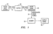
- FIG. 1 shows a digital image system 10 implementing the adaptive demosaicing algorithm 40 in accordance with the present invention.
- the digital image system 10 can be any digital imaging device, such as a digital camera, video camera, medical imaging device, etc.
- the digital image system 10 can also be a computer system, such as a personal computer or server, having a memory therein for storing image data.
- the adaptive demosaicing algorithm 40 can be within a digital imaging device or a part of an image processing software running on a personal computer or server.
- the digital image system 10 includes a digital image sensor 20, such as a CMOS sensor chip or a CCD sensor chip, which includes a two-dimensional array of pixels arranged in rows and columns.
- the digital image sensor may be covered by a color filter array (CFA), such that each pixel senses only one color.
- CFA color filter array
- the CFA may be the Bayer CFA described above, in which chrominance colors (red and blue) are interspersed amongst a checkerboard pattern of luminance colors (green). It should be understood that other CFA's may be used instead of the Bayer CFA described herein.
- the digital image sensor 20 provides raw data 25 containing the original red, blue and green pixel values to a digital signal processor 40, which applies the adaptive demosaicing algorithm of the present invention to the raw data 25 in order to interpolate the pixel values to obtain red, green and blue values at each pixel location.
- the raw data 25 is provided to the digital signal processor 40 blocks at a time. Thus, the raw data 25 is stored in a buffer 30 until the requisite amount of raw data 25 is present to begin processing.
- the number of raw data values 25 needed to begin processing depends on the type of processing.
- the pixel values corresponding to the raw data 25 are typically read off the sensor 20 one row at a time.
- at least one horizontal pixel neighbor, and preferably, one vertical pixel neighbor are stored within the buffer 30.
- one or more images may be stored in the buffer 30 at a time.
- the result of demosaicing is three interpolated color planes 35 (i.e., R, G and B), each containing the original values and the interpolated values. It should also be understood that other color spaces, such as yellow, cyan and magenta, can be used instead of the red, blue and green color space discussed herein.
- the interpolated red, green and blue color planes 35 are stored in a memory 50 until displayed or processed. It should be noted that the color planes 35 may be compressed using a compression method (not shown), such as the JPEG standard, prior to being stored in the memory 50.
- an output device 60 e.g., a video screen, computer screen or printer
- the compressed image is first decompressed, and the decompressed image is output to the output device 60.
- the digital signal processor 40 interpolates each image stored in the buffer 30 according to the adaptive demosaicing algorithm shown in FIG. 2.
- the adaptive demosaicing algorithm shown in FIG. 2 is referred to herein as the principal vector method (PVM).
- PVM is based on color edge detection and neighborhood voting. Within an image, there are many edges where the light intensity changes sharply. In order to produce a sharp output image, color interpolation should be directed along edges, rather than across them. Therefore, the PVM algorithm detects at every pixel location whether the pixel lies on an edge, and if so, estimates the orientation of that edge.
- edge herein refers to a pixel that lies on a boundary of an object or other boundary where the intensity changes sharply. The term “edge” does not refer to pixels that lie on one of the four natural boundaries of an image (i.e., pixels that lie on an edge of the sensor itself).
- both edge detection and edge orientation estimation may be attempted by using a single color plane, for example, green.
- a single color plane for example, green.
- edge detection and edge orientation estimation may be pooled from two or three color planes. The pooling of results from all three color planes typically provides better results. Therefore, the PVM algorithm shown in FIG. 2 illustrates the pooling of edge-related information (e.g., edge detection and edge orientation estimation) from the three color planes.
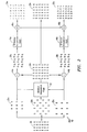
- the raw data 25 arrives at the digital signal processor 40, the raw data 25 is separated into three raw data color planes 25a, 25b and 25c, each having missing elements.
- the digital signal processor 40 applies adaptive interpolation logic 42 to the luminance raw data color plane 25b (i.e., green) in order to determine the missing luminance values at each location.
- the adaptive interpolation logic 42 interpolates the green value at each red or blue pixel, using either horizontal interpolation, vertical interpolation or a combination of horizontal and vertical interpolation, based on a voting mechanism, which will be described in more detail below with reference to FIGs. 4 and 5.
- the resulting interpolated green color plane 35b contains both the original green values, which are represented by the upper case G, and interpolated green values, which are represented by the lower case g.
- subtraction logic 44a and 44b computes the difference between the missing green value at each red or blue pixel location and the corresponding original red or blue pixel value. For example, taking the blue value B in the lower left-hand corner of the blue raw data color plane 25c, subtraction logic 44b subtracts the interpolated green value g in the lower left-hand corner of the interpolated green color plane 35b from the blue value B in the lower left-hand comer of the blue raw data color plane 25c.
- the resulting difference color planes 28a and 28b are interpolated by difference interpolated logic 46a and 46b, respectively, using any known method, such as median interpolation, bilinear interpolation or pixel replication.
- FIG. 2 illustrates the bilinear interpolation method, in which the red and blue difference color planes 28a and 28b are input to bilinear difference interpolation logic 46a and 46b, respectively, to produce red and blue difference interpolated color planes (not shown).
- the final red and blue interpolated color planes 35a and 35c are obtained by inputting the red and blue difference interpolated color planes to addition logic 48a and 48b, respectively, which adds the values of the red and blue difference interpolated color planes to the green values g and G of the green interpolated color plane 35b for the corresponding pixel locations. It is these interpolated red, blue and green color planes 35a, 35b and 35c, respectively, that are output from the DSP 40 to the memory 50 (shown in FIG. 1).
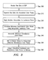
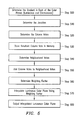
- FIG. 3 shows the steps for performing the PVM demosaicing algorithm .
- the DSP receives the raw data (step 300) and separates the raw data (step 310) into the three raw data color planes.
- the DSP applies the adaptive interpolation technique (step 320) (described below in FIGS. 4 and 5) to the luminance color plane (i.e., green).
- the DSP determines the difference chrominance color planes (i.e., red and blue) by subtracting the interpolated luminance values from the corresponding pixel chrominance color values (step 330).
- the missing red and blue values can be interpolated by first forming the differences at every red or blue pixel location as follows: This gives two difference images, D RG and D BG , whose values are respectively known only on the red or blue pixel locations.
- the DSP interpolates the difference chrominance color planes using the difference chrominance values (step 340).
- the difference chrominance color planes can be interpolated using any known method, such as median interpolation, bilinear interpolation or pixel replication.
- chrominance interpolation is pixel replication.
- each missing value is taken from the neighbor to the left, above, or diagonally above and left, whichever is nearest. Since the human visual system has a lower acuity in the chrominance colors than in the luminance colors, pixel replication provides good results in most situations.
- Bilinear interpolation offers some improvement over pixel replication with a moderate increase in complexity.
- the difference red or blue values are convolved with the following 3 x 3 filter: It should be noted that in the above filter, the multiplications and divisions are by powers of two, and hence can be accomplished with shifts.
- Median interpolation which is a nonlinear interpolation method, offers the best results, especially when there are defective pixels, but has the maximum complexity.
- Median interpolation has two steps. First, missing values having four diagonal neighbors are interpolated using the median of those four values. Second, the remaining missing pixels are interpolated by the median of north, south, east, and west neighbors.
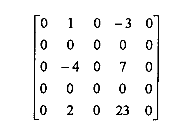
- the difference image D RG has the following values:
- the missing values having four diagonal neighbors are interpolated by the median of those neighbors.
- the result of the first step is:
- the locations marked * are also interpolated, but their values are not indicated because they depend on neighboring values lying outside of 5 x 5 region shown.
- the second step fills in the remaining missing values using the median of four north, south, east and west neighbors as follows:
- the final interpolated red and blue values can be determined by addition with the original and interpolated green values (step 350) as follows: These interpolated luminance (green) and chrominance (red and blue) color planes are output to the memory (step 360).
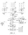
- the adaptive interpolation logic 42 will now be described in greater detail with reference to FIG. 4.
- respective gradient logic 100a, 100b and 100c determines the gradient 105a, 105b and 105c, respectively, of each of the color planes 25a, 25b and 25c, respectively
- Jacobian logic 110 determines the Jacobian 115 of the color planes 25a, 25b and 25c.
- the following is an explanation of the gradient 105a, 105b and 105c and Jacobian 115 of the color planes 25a, 25b and 25c.
- each component of the color image may be viewed as a function defined on the ( x , y ) domain, i.e., ( R(x , y) , G(x, y) , B(x, y) .
- R(x , y) a function defined on the ( x , y ) domain
- G(x, y) a function defined on the ( x , y ) domain
- a method for measuring the local orientation in color images starts by constructing the Jacobian (J) of the map from the 2-D plane to 3-D color space: where V denotes the gradient (i.e., the direction of steepest increase).
- the Jacobian captures the local first-order variation of the color image in the horizontal (x) and vertical (y) directions.
- the adaptive interpolation logic 42 B 1 G y 1 B 2 G x 1 R 1 G x 2 B 3 G y 2 B 4
- the horizontal green derivative and vertical green derivative of pixel R 1 must be calculated.
- the horizontal green derivative would be (G x1 - G x2 ), and the vertical green derivative would be (G y1 - G y2 ).
- the red gradients and blue gradients at pixel location R 1 are calculated in a similar manner.
- the blue horizontal blue derivative would be ((B 1 + B 3 )/2- (B 2 + B 4 )/2), and the vertical blue derivative would be ((B 1 + B 2 )/2 - (B 3 + B 4 )/2).
- the red derivatives would be calculated using horizontal and vertical red values that are not shown above.
- s 1 ⁇ s 2 ⁇ 0 are the singular values
- u k , v k are respectively, the left and right k -th singular vectors.
- J J ⁇ s 1 u 1 v t 1 .
- the vector u 1 Since the vector u 1 provides the direction of largest variation for the color image, the vector u 1 is the principal vector of the Jacobian, or simply the "principal vector.”
- each of the three columns of J is the gradient in one of the R , G, B color planes.
- the edge can be said to be consistent in the three planes.
- the principal vector points in the same direction as the gradients, and the smaller singular value, s 2 , equals 0.
- the "principal vector” provides the best "fit” to the three gradients.
- the "principal vector" u 1 points in the direction of greatest change.
- the vector u 2 which is orthogonal to u 1 and points in the direction of least change, is used as the interpolation direction.
- I 1 is the result of interpolating along u 1
- I 2 is the result of interpolating along u 2 .
- I h and I v respectively, denote the interpolants in the horizontal and vertical directions.
- I h and I v may be computed by forming simple linear combinations of pixel values along rows (for I h ) or, alternatively, along columns (for I v ).
- u 1 [ u 1 (1), u 1 (2)] t
- u 2 [ u 2 (1), u 2 (2)] t
- both u 1 and u 2 are unit-length vectors.
- I 1 u 1 (1) 2 I h + u 1 (2) 2 I v
- I 2 u 2 (1) 2 I h + u 2 (2) 2 I v
- I ⁇ I h + (1 - ⁇ ) I v
- I ⁇ ⁇ u 1 (1) 2 + (1 - ⁇ ) u 2 (1) 2 .
- I h the value of I in Equation 13 requires three terms: I h , I v , and ⁇ .
- the first two terms, I h and I v are straightforward to compute, since they involve only simple linear combinations of pixel values.
- the third term, ⁇ is based on terms that are extracted from the SVD of J . Potentially, this requires computation of the SVD of J at every pixel, which is prohibitive.
- approximate values for ⁇ can be estimated.
- the adaptive interpolation logic 42 can also assume that the direction of the principal vector u 1 can be quantized to be one of only two possibilities: horizontal or vertical. Thus, if the inclination of u 1 from the horizontal axis is less than ⁇ 45, u 1 is horizontal, and otherwise u 1 is vertical. Equivalently, u 1 is horizontal if
- the adaptive interpolation logic 42 can further assume that the decision whether the principal vector is horizontal or vertical can be made by applying a majority rule.
- the majority rule is as follows: if the majority of elements of the bottom row of the Jacobian 115 (which are vertical derivatives) exceed in absolute value the corresponding elements of the top row of the Jacobian 115 (which are horizontal derivatives), the principal vector is vertical. Otherwise, the principal vector is horizontal. For example, if the Jacobian 115 is two of the elements of the top row exceed their counterparts in the bottom row in absolute value. Thus, the principal vector for the above Jacobian 115 is assumed to be horizontal.
- the majority rule provides the direction of the principal vector, the majority rule does not by itself determine ⁇ among the possibilities ⁇ 0, 1 ⁇ 2, 1 ⁇ .
- the "principal vector" itself is not used as the interpolation direction. Rather, the interpolation direction is orthogonal to the direction of the "principal vector.” Therefore, when selecting the weighting factor ⁇ , the adaptive interpolation logic 42 considers the actual number of horizontal derivatives exceeding vertical derivatives (or vice-versa).
- ⁇ is set to 0 to force vertical interpolation (which is the direction orthogonal to the principal vector).
- Vertical interpolation is preferred for pixels that lie on a vertical edge within an image. Since there is a sharp change in intensity at horizontally adjacent pixels, interpolating horizontally for pixels that lie on a vertical edge will not provide an adequate interpolated value.
- the above technique for selecting the weighting factor ⁇ detects that a pixel is on a vertical edge because the first-order derivative for a vertical edge pixel is higher in the horizontal direction than in the vertical direction. If the weighting factor ⁇ corresponds to the pixel lying on a vertical edge, vertical interpolation is applied.
- ⁇ is set to 1 to force horizontal interpolation.
- Horizontal interpolation is preferred for pixels that lie on a horizontal edge within an image for the same reasons as discussed above in connection with vertical edge pixels.
- ⁇ would be set to 1 ⁇ 2 to include both horizontal and vertical interpolation since the principal vector fit is poorest where the gradients are not parallel. The fit is usually poorest when a pixel does not lie on an edge, and therefore, both horizontal and vertical interpolation are preferred.
- the selection mechanism for ⁇ described above is implemented by column vote logic 120 within the adaptive interpolation logic 42.
- the column vote logic 120 takes each column of the Jacobian 115 for a particular pixel, and assigns each column one vote.
- three column votes 125 are collected at each pixel.
- This voting scheme may be further extended to accommodate neighborhood pixel votes as well as votes at each pixel.
- the adaptive interpolation logic 42 can consider neighborhood vote data 140 in addition to the column votes 125. For example, at two neighboring pixels, if two or more columns of the Jacobian 115 of each neighboring pixel voted horizontal, the neighborhood vote data 140 would include two horizontal votes. It should be noted that although this extended voting scheme does not use the individual Jacobian 115 column votes at neighboring pixels, and only considers the result of the majority rule, in other embodiments, the extended voting scheme may include each column vote at neighboring pixels as well.
- the neighborhood vote data 140 may be defined to be data from any subset of pixels preceding the current pixel in a raster scan of the image.
- the neighborhood vote data 140 can include data from the adjacent pixels to the left and above the current pixel. This neighborhood is referred to as the neighborhood of distance one. However, it should be understood that other neighborhoods of different distances may also be chosen.
- the column vote logic 110 determines the majority vote 135 (i.e., either vertical or horizontal), and stores the majority vote 135 in a memory 130 (which could be the same memory 50 as shown in FIG. 1). For example, if the majority vote 135 is horizontal (i.e., two or more of the columns voted horizontal), the column vote logic 110 can store a "1" in memory 130 for that pixel. If the majority vote 135 is vertical, the column vote logic 110 can store a "0" in memory 130 for that pixel.
- the adaptive interpolation logic 42 interpolates the raw data 25a, 25b and 25c, the outcome of the majority rule on a number of previous lines corresponding to the distance of the neighborhood N is stored in the memory 130.
- the memory requirement is only 1 bit per pixel for each line that is stored.
- addition logic 150 adds the column votes 125 for the current pixel supplied by the column vote logic 110 to the neighborhood votes supplied by the neighborhood vote data 140.
- the result 155 of the addition of votes is passed to weight determining logic 160 to assign the weighting factor ⁇ .
- the steps for interpolating the luminance color plane i.e., determining the missing green values at the chrominance pixel locations
- the gradient in each of the raw data chrominance color planes i.e., red and blue
- the first-order derivative in the horizontal and vertical directions step 500. It should be noted that other measures of the degree of change, such as the second-order derivatives, can be used instead of the first-order derivatives described herein.
- each column of Jacobian i.e., each gradient
- votes either horizontal or vertical step 520.
- Each of the gradients supplies a respective vote, and the majority vote (i.e., either vertical or horizontal depending on which had the most votes) is stored in the memory (step 530).
- the DSP processes the raw data row by row. Therefore, although the raw data for the adjacent pixels to the right and below the pixel location currently being processed may be known, the majority vote for these adjacent pixels is not yet known. So, typically when considering neighborhood votes (step 540), the only adjacent pixels that have completed voting and stored the majority vote in the memory are the adjacent pixels to the left and above the pixel location currently being processed. For example, again considering the pixel location R 1 of the following Bayer pattern B 1 G y 1 B 2 G x 1 R 1 G x 2 , B 3 G y 2 B 4 the neighborhood vote data would include the majority vote from G x1 and G y1 . It should be understood that the number of neighborhood votes can be increased to consider neighbors two or more pixels away from the currently processed pixel.
- the majority vote from each of the adjacent pixels to the left and above the pixel location currently being processed are added to the column votes for the currently processed pixel location, resulting in five total votes (step 550).
- the weighting factor ⁇ is determined based on the total number of horizontal votes verses the total number of vertical votes, as described above (step 560). For example, again considering the pixel location R 1 above, if the red gradient (column) voted horizontal, the blue gradient (column) voted vertical and the green gradient (column) voted horizontal, the majority vote of the pixel location R 1 is horizontal. In addition, if the majority vote from the pixel location G x1 was horizontal and the majority vote for the pixel location G y1 was vertical, the total number of horizontal votes is 3 and the total number of vertical votes is 2.
- one or more thresholds based on either the total number of horizontal votes or the total number of vertical votes can be set to determine the weighting factor ⁇ .
- two thresholds, T 1 and T 2 were set based on the total number of horizontal votes.
- Interpolation results are usually improved by applying a linear prediction.
- the linear prediction is f ( x ) ⁇ f ( x o )+( x - x o ) f' ( x o ).
- the gains are high, and consequently so is the noise, and ⁇ would be equal to 0 or to a small positive value.
- ⁇ would be equal to 1.
- Equation 18 A similar interpolation as shown in Equation 18 is used for horizontal interpolation for lines with blue and green, and also for vertical interpolation.
- the average of horizontal and vertical interpolations are used.
- the interpolated luminance color plane is output (step 580) by the adaptive interpolation logic shown in FIG. 2 to be used in interpolating the chrominance color planes, using any known demosaicing technique, as described above in connection with FIG. 2.
- the adaptive demosaicing PVM algorithm images realize a reduction in isolated interpolation errors. Therefore, using a neighborhood provides smoother reconstruction of an image than previous demosaicing methods.
- FIG. 6A illustrates the exemplary steps for compensating for G1 :G2 mismatch.
- the green pixels within the raw data 25 shown in FIG. 2 fall into two categories: (1) those with red pixels as horizontal neighbors and blue pixels as vertical neighbors, called "G1: pixels; and (2) those with the blue pixels as horizontal neighbors and red pixels as vertical neighbors, called "G2" pixels.
- the G1 pixels often exhibit significantly different values from the G2 pixels to the same illumination, due to factors including sensor architecture and CFA misalignment. The variation in green values is most noticeable in image regions where green is uniform, and appears as a checkerboard pattern when examined closely.
- the mismatch between G1 and G2 pixels may be corrected using two pre-processing steps applied prior to the PVM demosaicing algorithm.
- the first step which is shown in FIG. 6A and referred to as the "mean balancing" step, is a global correction.
- the mean balancing step proceeds by measuring the mean value of the G1 pixels of the entire image (step 600) and, separately, the mean value of the G2 pixels of the entire image (step 610). If the two mean values are equal (step 620), no mismatch exists and processing is completed (step 630). However, if the two mean values are not equal (step 620), a difference percentage between the two mean values is determined (step 640). Thereafter, the green pixel values of the smaller of the two means (G1 mean or G2 mean) are scaled up using the difference percentage (step 650).
- This mean balancing step may be applied prior to demosaicing using the PVM algorithm.
- digital cameras often take multiple images to ensure the exposure is correct before selecting the image to permanently store. Therefore, this mean balancing step may be performed on one of the images taken prior to the stored image.
- the second step is shown in FIG. 6B and referred to as "adaptive smoothing". This second step may also be performed prior to interpolation of the green color plane, and preferably after the "mean balancing" step.
- the adaptive smoothing step applies a smoothing filter to the raw green values at pixels that do not lie on edges, and uses the smoothed green values for interpolation. Whether a pixel lies on an edge may be determined by computing the sum of the absolute values of entries from the Jacobian matrix shown in Equation 6 (step 660).
- the pixel does not lie on an edge, and hence smoothing may be applied to the raw green value. If the sum is not less than the predefined threshold (step 670), the pixel does lie on an edge and processing ends with respect to this pixel (step 680).
- a predefined threshold i.e., in experimental tests, a threshold of 64 was used
- the green column of the Jacobian of a green pixel value is computed by taking differences of similar green pixels, i.e., G1 values with G1 values, G2 values with G2 values, but not G1 values with G2 values.
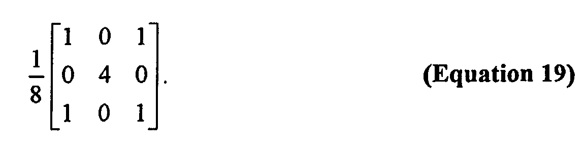
- smoothing may be accomplished by convolving the green value with a 3 x 3 filter (step 690) as follows:
- Equation 19 assumes a Bayer pattern similar to the following: G 1 R G 1 B G 2 B G 1 R G 1
- a G2 value is surrounded by four G1 values.
- the G2 value is multiplied by four and added to each of the surrounding G1 values. The total after addition is then divided by eight. The resulting value is used as the G2 value.
- FIG. 7 illustrates the steps for sharpening an image. Since an image is sampled only at pixel locations, there is an inherent under-sampling of an image, which may lead to the elimination of some high-frequencies in the image. Therefore, in order to sharpen an image, the second derivative is added back to the original image. For example, assume the following Bayer pattern: G 11 R 12 G 13 R 14 G 15 B 21 G 22 B 23 G 24 B25 G 31 R 32 G 33 R 34 G 35 B41 G42 B43 G44 B45 G51 R52 G53 R54 G55 The second order horizontal derivative of G33 can be estimated by: (2G33 - G31 - G35). Similarly, the second order vertical derivative of G33 can be estimated by: (2G33 - G53 - G13).
- I is any of the fully-populated color planes, red, green, or blue, that are obtained after demosaicing.
- the user sets the adjustable parameter ⁇ (step 700).
- the adjustable parameter ⁇ is set to 0 when no sharpening is desired and 1 when the maximum amount of sharpening is desired. However, it should be understood that any value between 0 and 1 may be used for ⁇ . If the adjustable parameter ⁇ is set to 0 (step 710), no sharpening is performed (step 720). If the adjustable parameter ⁇ is not set to 0 (step 710), the Laplacian is determined (step 730), multiplied by the adjustable parameter ⁇ (step 740) and added back to the original pixel value (step 750).
- FIG. 8 illustrates the steps for reducing noise in an image.
- the type of adaptive smoothing proposed above for G1:G2 compensation can be easily extended to the red and blue pixels, for the purpose of noise reduction.
- the adaptive smoothing for noise reduction applies a smoothing filter to the raw red and blue values at pixels that do not lie on edges, and uses the smoothed red and blue values for interpolation.
- whether a pixel lies on an edge may be determined by computing the sum of absolute values of entries from the Jacobian matrix shown in Equation 6 (step 800).
- step 810 If the sum of the absolute values of entries in the Jacobian is less than a predefined threshold (step 810), the pixel does not lie on an edge, and hence smoothing may be applied to the raw red or blue value. If the sum is not less than the predefined threshold (step 810), the pixel does lie on an edge and processing ends (step 820).
- the 5 x 5 smoothing filter for noise reduction is as follows (step 830): Adaptive smoothing using the above filter for red and blue pixel values has the advantage of reducing noise without blurring edges.
Landscapes
- Engineering & Computer Science (AREA)
- Physics & Mathematics (AREA)
- General Physics & Mathematics (AREA)
- Theoretical Computer Science (AREA)
- Multimedia (AREA)
- Signal Processing (AREA)
- Image Processing (AREA)
- Color Television Image Signal Generators (AREA)
- Facsimile Image Signal Circuits (AREA)
- Color Image Communication Systems (AREA)
- Editing Of Facsimile Originals (AREA)
Abstract
Description
| G | R | G | R | G |
| B | G | B | G | B |
| G | R | G | R | G |




| B 1 | Gy 1 | B 2 |
| Gx 1 | R 1 | Gx 2 |
| B 3 | Gy 2 | B 4 |

| B 1 | Gy 1 | B 2 |
| Gx 1 | R 1 | Gx 2, |
| B 3 | Gy 2 | B 4 |
R2 Gx1 R1 Gx2 R3. The linear prediction of the green value at R1 from Gx1 is, using the difference approximation f'(xo ) = (R 1 - R 2)/2, and setting x - x o = 1:
| G 1 | R | G 1 |
| B | G 2 | B |
| G 1 | R | G 1 |
| G11 | R12 | G13 | R14 | G15 |
| B21 | G22 | B23 | G24 | B25 |
| G31 | R32 | G33 | R34 | G35 |
| B41 | G42 | B43 | G44 | B45 |
| G51 | R52 | G53 | R54 | G55 |


Claims (33)
- A method for determining whether a pixel lies on an edge of a digital image, said method comprising:determining, for said pixel, a first edge-orientation of a first color and a second edge-orientation of a second color; andproviding respective interpolation votes associated with said first edge-orientation and said second edge-orientation to determine a selected interpolation orientation, said respective interpolation votes being either a first interpolation orientation or a second interpolation orientation, said selected interpolation orientation being based on the number of said interpolation votes for said first interpolation orientation and said second interpolation orientation.
- The method of Claim 1, wherein said first and second edge-orientations are first and second gradients, respectively, said first and second gradients forming a Jacobian of said pixel.
- The method of Claim 2, wherein said first interpolation orientation is a horizontal interpolation and said second interpolation orientation is a vertical interpolation, and wherein said step of providing further comprises:setting a first one of said interpolation votes associated with said first gradient, said first interpolation vote being set as said horizontal interpolation when the absolute value of a row component of said first gradient is lower than the absolute value of a column component of said first gradient, said first interpolation vote being set as said vertical interpolation when the absolute value of said column component of said first gradient is lower than the absolute value of said row component of said first gradient;setting a second one of said interpolation votes associated with said second gradient, said second interpolation vote being set as said horizontal interpolation when the absolute value of a row component of said second gradient is lower than the absolute value of a column component of said second gradient, said second interpolation vote being set as said vertical interpolation when the absolute value of said column component of said second gradient is lower than the absolute value of said row component of said second gradient; andselecting either said horizontal interpolation, said vertical interpolation or a combination of said vertical interpolation and said horizontal interpolation for said selected interpolation orientation based on said steps of setting.
- The method of Claim 3, wherein said step of selecting further comprises:providing neighborhood vote data, said neighborhood vote data including a majority vote from at least one adjacent pixel, said majority vote being horizontal interpolation when the majority of said interpolation votes from said adjacent pixel are horizontal interpolation and vertical interpolation when the majority of said interpolation votes from said adjacent pixel are vertical interpolation; andadding said neighborhood vote data to said interpolation votes to determine said selected interpolation orientation.
- The method of Claim 4, wherein said step of selecting further comprises:setting at least a first threshold and a second threshold associated with the number of said interpolation votes for either said horizontal interpolation or said vertical interpolation; andselecting said combination of said vertical and horizontal interpolations as said selected interpolation orientation when the number of said interpolation votes for either said horizontal interpolation or said vertical interpolation falls in between said first and second thresholds.
- A method for demosaicing a digital image represented as values at pixel locations, said method comprising:receiving a set of first color values and a set of said second color values;determining for a given one of said first color values associated with a given one of said pixel locations a first degree of change using said set of first color values and a second degree of change using said set of second color values, said first and second degrees of change each having a row component and a column component;comparing said row component to said column component for both said first and second degrees of change to determine a selected interpolation orientation.
- The method of Claim 6, further comprising:interpolating a missing second color value associated with said given pixel location using said selected interpolation orientation.
- The method of Claim 7, wherein said step of interpolating further comprises:interpolating said missing second color value by applying a linear prediction function that uses said first color values and said second color values.
- The method of Claim 8, wherein said step of interpolating further comprises:determining a number of said first and second color values that are below a low-light threshold value; andturning off said linear prediction function when said number exceeds an additional threshold value.
- The method of Claim 7, further comprising:determining a difference value by subtracting said interpolated missing second color value from said given first color value; andinterpolating a missing first color value using at least said difference value, said missing first color value being associated with one of said pixel locations that did not produce said first color value.
- The method of Claim 6, wherein said first and second degrees of change are first and second gradients, respectively, said first and second gradients forming a Jacobian of said given first color value, and wherein said step of comparing further comprises:supplying, by each of said first and second gradients, a respective interpolation vote, said interpolation vote being either a first interpolation orientation or a second interpolation orientation, said selected interpolation orientation being based on the number of said interpolation votes for said first interpolation orientation and said second interpolation orientation.
- The method of Claim 11, wherein said first interpolation orientation is a horizontal interpolation and said second interpolation orientation is a vertical interpolation, and wherein said step of supplying further comprises:setting said interpolation vote as said horizontal interpolation, by a respective one of said first and second gradients, when the absolute value of said row component of said respective gradient is lower than the absolute value of said column component of said respective gradient;setting said interpolation vote as said vertical interpolation, by said respective gradient, when the absolute value of said column component of said respective gradient is lower than the absolute value of said row component of said respective gradient; andselecting either said horizontal interpolation, said vertical interpolation or a combination of said vertical interpolation and said horizontal interpolation for said selected interpolation orientation based on said steps of setting.
- The method of Claim 12, wherein said step of selecting further comprises:providing neighborhood vote data, said neighborhood vote data including a majority vote from at least one adjacent one of said pixel locations to said given pixel location, said majority vote being horizontal interpolation when the majority of said interpolation votes from said adjacent one of said pixel locations are horizontal interpolation and vertical interpolation when the majority of said interpolation votes from said adjacent one of said pixel locations are vertical interpolation; andadding said neighborhood vote data to said interpolation votes to determine said selected interpolation orientation.
- The method of Claim 13, wherein said step of selecting further comprises:setting at least a first threshold and a second threshold associated with the number of said interpolation votes for either said horizontal interpolation or said vertical interpolation; andselecting said combination of said vertical and horizontal interpolations as said selected interpolation orientation when the number of said interpolation votes for either said horizontal interpolation or said vertical interpolation falls in between said first and second thresholds.
- The method of Claim 6, wherein said first color values are chrominance color values and said second color values are luminance color values.
- The method of Claim 15, further comprising:determining a first mean luminance value of a first group of said luminance color values and a second mean luminance value of a second group of said luminance color values;determining a difference percentage between said first mean luminance value and said second mean luminance value; andincreasing said luminance color values of said first group by said difference percentage when said first mean luminance value is lower than said second mean luminance value.
- The method of Claim 15, further comprising:determining a Jacobian of a given one of said luminance color values from said set of luminance color values;determining a first sum of the absolute values of the values within said Jacobian; andif said first sum is less than a predefined threshold:multiplying said given luminance color value by four,adding said luminance color values of four diagonally adjacent pixel locations to obtain a second sum, anddividing said second sum by eight.
- The method of Claim 6, further comprising:determining a Jacobian of said given first color value;determining a first sum of the absolute values of the values within said Jacobian; andif said first sum is less than a predefined threshold:multiplying said given first color value by eight,adding said first color values of eight nearest pixel locations to obtain a second sum, anddividing said second sum by sixteen.
- A digital image system for demosaicing a digital image represented as values at pixel locations, said system comprising:a processor adapted to receive a set of first color values and a set of second color values, said processor being further adapted to determine for a given one of said first color values associated with a given one of said pixel locations a first degree of change using said set of first color values and a second degree of change using said set of second color values, said first and second degrees of change each having a row component and a column component, said row component being compared to said column component for both said first and second degrees of change to determine a selected interpolation orientation.
- The system of Claim 20, wherein said processor is further adapted to interpolate a missing second color value for said pixel location associated with said given pixel location using said selected interpolation orientation.
- The system of Claim 20, wherein said processor is further adapted to interpolate said missing second color value by applying a linear prediction function that uses said first color values and said second color values.
- The system of Claim 21, wherein said processor is further adapted to determine a number of said first and second color values that are below a low-light threshold value, said processor being further adapted to turn off said linear prediction function when said number exceeds an additional threshold value.
- The system of Claim 20, wherein said processor is further adapted to receive a set of third color values, said sets of first, second and third color values each being associated with a different color, said processor further being capable of determining a third degree of change associated with said third color values.
- The system of Claim 23, wherein said processor is further adapted to determine a difference value by subtracting said interpolated missing second color value from said given first color value and interpolate a missing first color value for said pixel location associated with said second or third color values using at least said difference value.
- The system of Claim 23, wherein said first, second and third degrees of change are first, second and third gradients, respectively, said first, second and third gradients forming a Jacobian of said given first color value, each of said first, second and third gradients supplying a respective interpolation vote, said interpolation vote being either a first interpolation orientation or a second interpolation orientation, said selected interpolation orientation being based on the number of said interpolation votes for said first interpolation orientation and said second interpolation orientation.
- The system of Claim 25, wherein said first interpolation orientation is a horizontal interpolation using at least one or more of said second color values from said pixel locations within the same row of said pixel locations as said given pixel location and said second interpolation orientation is a vertical interpolation using at least one or more of said second color values from said pixel locations within the same column of said pixel locations as said given pixel location, said interpolation vote of a respective one of said first, second and third gradients being said horizontal interpolation when the absolute value of said row component of said respective gradient is lower than the absolute value of said column component of said respective gradient and vertical interpolation when the absolute value of said column component of said respective gradient is lower than the absolute value of said row component of said respective gradient, said selected interpolation orientation being selected from the group consisting of: said horizontal interpolation, said vertical interpolation or a combination of said vertical interpolation and said horizontal interpolation.
- The system of Claim 26, further comprising:a memory capable of storing neighborhood vote data, said neighborhood vote data including a majority vote from at least one adjacent one of said pixel locations to said given pixel location, said majority vote being horizontal interpolation when the majority of said interpolation votes from said adjacent one of said pixel locations are horizontal interpolation and vertical interpolation when the majority of said interpolation votes from said adjacent one of said pixel locations are vertical interpolation, said neighborhood vote data being added to said interpolation votes to determine said selected interpolation orientation.
- The system of Claim 27, further comprising:at least a first threshold and a second threshold associated with the number of said interpolation votes for either said horizontal interpolation or said vertical interpolation, said selected interpolation orientation being said combination of said vertical and horizontal interpolations when the number of said interpolation votes for either said horizontal interpolation or said vertical interpolation falls in between said first and second thresholds.
- The system of Claim 19, wherein said first color values are chrominance color values and said second color values are luminance color values.
- The system of Claim 29, wherein said processor is further adapted to determine a first mean luminance value of a first group of said luminance color values and a second mean luminance value of a second group of said luminance color values, said processor further being adapted to determine a difference percentage between said first mean luminance value and said second mean luminance value and increase said luminance color values of said first group by said difference percentage when said first mean luminance value is lower than said second mean luminance value.
- The system of Claim 29, wherein said processor is further adapted to determine a Jacobian of a given one of said luminance color values from said set of luminance color values and determine a first sum of the absolute values of the values within said Jacobian, said processor being further adapted to multiply said given luminance color value by four, add said luminance color values of four diagonally adjacent pixel locations to obtain a second sum and divide said second sum by eight when said first sum is less than a predefined threshold.
- The system of Claim 19, wherein said processor is further adapted to determine a Laplacian of a select color value within either said set of first color values or said set of second color values and add said Laplacian multiplied by an adjustable parameter to said select color value.
- The system of Claim 19, wherein said processor is further adapted to determine a Jacobian of said given first color value and determine a first sum of the absolute values of the values within said Jacobian, said processor being further adapted to multiply said given first color value by eight, add said first color values of eight nearest pixel locations to obtain a second sum and divide said second sum by sixteen when said first sum is less than a predefined threshold.
Applications Claiming Priority (2)
| Application Number | Priority Date | Filing Date | Title |
|---|---|---|---|
| US09/940,825 US7088392B2 (en) | 2001-08-27 | 2001-08-27 | Digital image system and method for implementing an adaptive demosaicing method |
| US940825 | 2001-08-27 |
Publications (3)
| Publication Number | Publication Date |
|---|---|
| EP1289310A2 true EP1289310A2 (en) | 2003-03-05 |
| EP1289310A3 EP1289310A3 (en) | 2005-12-07 |
| EP1289310B1 EP1289310B1 (en) | 2011-07-13 |
Family
ID=25475488
Family Applications (1)
| Application Number | Title | Priority Date | Filing Date |
|---|---|---|---|
| EP02009959A Expired - Lifetime EP1289310B1 (en) | 2001-08-27 | 2002-05-03 | Method and system for adaptive demosaicing |
Country Status (3)
| Country | Link |
|---|---|
| US (1) | US7088392B2 (en) |
| EP (1) | EP1289310B1 (en) |
| JP (1) | JP4352371B2 (en) |
Cited By (18)
| Publication number | Priority date | Publication date | Assignee | Title |
|---|---|---|---|---|
| WO2006084266A1 (en) * | 2005-02-04 | 2006-08-10 | Qualcomm Incorporated | Adaptive color interpolation |
| WO2006129096A3 (en) * | 2005-06-01 | 2007-05-03 | Snell & Wilcox Ltd | Method and apparatus for spatial interpolation of colour images |
| WO2007084930A3 (en) * | 2006-01-18 | 2007-11-15 | Qualcomm Inc | Method and apparatus for adaptive and self-calibrated sensor green channel gain balancing |
| WO2007110829A3 (en) * | 2006-03-27 | 2007-12-06 | Koninkl Philips Electronics Nv | Method and arrangement for generating a color video signal |
| DE102006028735A1 (en) * | 2006-06-20 | 2007-12-27 | Sci-Worx Gmbh | Device for interpolating and filtering digital image data |
| CN100399834C (en) * | 2004-05-17 | 2008-07-02 | 华晶科技股份有限公司 | Method and device for determining edge trend of interested pixel |
| EP1569442A4 (en) * | 2002-12-02 | 2009-08-12 | Olympus Corp | Image pickup device |
| US7620241B2 (en) * | 2004-11-30 | 2009-11-17 | Hewlett-Packard Development Company, L.P. | Artifact reduction in a digital video |
| EP2124187A1 (en) * | 2008-05-22 | 2009-11-25 | Telefonaktiebolaget LM Ericsson (PUBL) | Apparatus and method for demosaicing |
| US7995840B2 (en) | 2008-03-28 | 2011-08-09 | Seiko Epson Corporation | Image processing apparatus, image processing method, and program for attaining image processing |
| US8040385B2 (en) | 2002-12-02 | 2011-10-18 | Olympus Corporation | Image pickup apparatus |
| WO2012004306A1 (en) | 2010-07-07 | 2012-01-12 | DigitalOptics Corporation Europe Limited | Demosaicing |
| US8111299B2 (en) | 2008-08-15 | 2012-02-07 | Seiko Epson Corporation | Demosaicking single-sensor camera raw data |
| US8761504B2 (en) | 2006-11-29 | 2014-06-24 | President And Fellows Of Harvard College | Spatio-spectral sampling paradigm for imaging and a novel color filter array design |
| EP1977613B1 (en) * | 2006-01-27 | 2015-10-07 | Omnivision Technologies, Inc. | Interpolation of panchromatic and color pixels |
| CN105049820A (en) * | 2014-04-25 | 2015-11-11 | 佳能株式会社 | IMAGE PROCESSING APPARATUS, IMAGING APPARATUS, and IMAGE PROCESSING METHOD |
| CN110458766A (en) * | 2019-07-11 | 2019-11-15 | 天津大学 | A Snapshot Hyperspectral Image Demosaicing Method |
| CN113852768A (en) * | 2021-09-24 | 2021-12-28 | 中音讯谷科技有限公司 | Audio and video image intelligent control system based on FPGA technology |
Families Citing this family (97)
| Publication number | Priority date | Publication date | Assignee | Title |
|---|---|---|---|---|
| US6707937B1 (en) * | 2000-07-14 | 2004-03-16 | Agilent Technologies, Inc. | Interpolation of edge portions of a digital image |
| US6900833B2 (en) * | 2001-01-15 | 2005-05-31 | Pentax Corporation | Image interpolating device |
| US7088392B2 (en) * | 2001-08-27 | 2006-08-08 | Ramakrishna Kakarala | Digital image system and method for implementing an adaptive demosaicing method |
| US20030117507A1 (en) * | 2001-12-21 | 2003-06-26 | Nasser Kehtarnavaz | Color filter array interpolation |
| US7196829B2 (en) * | 2002-01-10 | 2007-03-27 | Micron Technology Inc. | Digital image system and method for combining sensing and image processing on sensor with two-color photo-detector |
| US6992707B2 (en) * | 2002-03-06 | 2006-01-31 | Hewlett-Packard Development Company, L.P. | Delayed encoding based joint video and still image pipeline with still burst mode |
| JP4065155B2 (en) * | 2002-07-12 | 2008-03-19 | オリンパス株式会社 | Image processing apparatus and image processing program |
| JP4019417B2 (en) * | 2003-01-14 | 2007-12-12 | ソニー株式会社 | Image processing apparatus and method, recording medium, and program |
| US20070292022A1 (en) * | 2003-01-16 | 2007-12-20 | Andreas Nilsson | Weighted gradient based and color corrected interpolation |
| EP1439715A1 (en) * | 2003-01-16 | 2004-07-21 | Dialog Semiconductor GmbH | Weighted gradient based colour interpolation for colour filter array |
| JP4270892B2 (en) * | 2003-01-27 | 2009-06-03 | Hoya株式会社 | False color reduction device |
| US7333678B1 (en) * | 2003-05-20 | 2008-02-19 | Micronas Usa, Inc. | Edge adaptive demosaic system and method |
| EP1641283B1 (en) * | 2003-06-12 | 2019-01-09 | Nikon Corporation | Image processing method, image processing program, image processor |
| US7768500B2 (en) * | 2003-06-16 | 2010-08-03 | Humanscale Corporation | Ergonomic pointing device |
| US7269295B2 (en) * | 2003-07-31 | 2007-09-11 | Hewlett-Packard Development Company, L.P. | Digital image processing methods, digital image devices, and articles of manufacture |
| US7430334B2 (en) * | 2003-07-31 | 2008-09-30 | Hewlett Packard Development Company, L.P. | Digital imaging systems, articles of manufacture, and digital image processing methods |
| JP4128585B2 (en) * | 2003-12-22 | 2008-07-30 | 三菱電機株式会社 | Pixel signal processing apparatus and pixel signal processing method |
| US7440016B2 (en) * | 2003-12-22 | 2008-10-21 | Hewlett-Packard Development Company, L.P. | Method of processing a digital image |
| KR20050062709A (en) * | 2003-12-22 | 2005-06-27 | 삼성전자주식회사 | Apparatus for digital image processing and method thereof |
| EP1705902A4 (en) * | 2003-12-26 | 2008-12-17 | Olympus Corp | IMAGE INPUT APPARATUS |
| US7525584B2 (en) * | 2004-01-05 | 2009-04-28 | Lifesize Communications, Inc. | Fast edge directed demosaicing |
| US8165389B2 (en) * | 2004-03-15 | 2012-04-24 | Microsoft Corp. | Adaptive interpolation with artifact reduction of images |
| JP4037381B2 (en) * | 2004-03-31 | 2008-01-23 | 富士フイルム株式会社 | Optical information reading method and apparatus |
| US7418130B2 (en) * | 2004-04-29 | 2008-08-26 | Hewlett-Packard Development Company, L.P. | Edge-sensitive denoising and color interpolation of digital images |
| CA2466466C (en) * | 2004-05-05 | 2020-05-26 | Dominion Voting Systems Corporation | System, method and computer program for vote tabulation with an electronic audit trail |
| US7376288B2 (en) * | 2004-05-20 | 2008-05-20 | Micronas Usa, Inc. | Edge adaptive demosaic system and method |
| US7557799B2 (en) | 2004-06-17 | 2009-07-07 | Avago Technologies Ecbu Ip (Singapore) Pte. Ltd. | System for determining pointer position, movement, and angle |
| ITVA20040038A1 (en) * | 2004-10-04 | 2005-01-04 | St Microelectronics Srl | METHOD OF INTERPOLATION OF THE COLOR OF AN IMAGE ACQUIRED BY A DIGITAL SENSOR THROUGH DIRECTIONAL FILTERING |
| US7864221B2 (en) * | 2004-10-15 | 2011-01-04 | Lifesize Communications, Inc. | White balance for video applications |
| US7545435B2 (en) * | 2004-10-15 | 2009-06-09 | Lifesize Communications, Inc. | Automatic backlight compensation and exposure control |
| EP1650979A1 (en) * | 2004-10-21 | 2006-04-26 | STMicroelectronics S.r.l. | Method and system for demosaicing artifact removal |
| TWI249336B (en) * | 2004-11-15 | 2006-02-11 | Ind Tech Res Inst | Method and apparatus of color filter array demosaicking for digital image acquisition system |
| CN100459718C (en) * | 2004-11-26 | 2009-02-04 | 财团法人工业技术研究院 | Method and device for demosaicing color filter array image |
| JP4783795B2 (en) * | 2005-01-27 | 2011-09-28 | タンデント ビジョン サイエンス インコーポレーティッド | Distinguishing between illumination and reflection boundaries |
| JP4375269B2 (en) * | 2005-03-29 | 2009-12-02 | セイコーエプソン株式会社 | Print control method, print control apparatus, and print control program |
| US7751642B1 (en) * | 2005-05-18 | 2010-07-06 | Arm Limited | Methods and devices for image processing, image capturing and image downscaling |
| KR100782812B1 (en) * | 2005-06-15 | 2007-12-06 | 삼성전자주식회사 | Edge adaptive color interpolation method and apparatus |
| US7613357B2 (en) * | 2005-09-20 | 2009-11-03 | Gm Global Technology Operations, Inc. | Method for warped image object recognition |
| WO2007038099A2 (en) * | 2005-09-21 | 2007-04-05 | Plain Sight Systems | Multispectral imaging and non-linear filtering of vector valued data |
| US7840086B2 (en) * | 2005-10-12 | 2010-11-23 | The Regents Of The University Of California | Method for inpainting of images |
| US7486844B2 (en) * | 2005-11-17 | 2009-02-03 | Avisonic Technology Corporation | Color interpolation apparatus and color interpolation method utilizing edge indicators adjusted by stochastic adjustment factors to reconstruct missing colors for image pixels |
| US20070133902A1 (en) * | 2005-12-13 | 2007-06-14 | Portalplayer, Inc. | Method and circuit for integrated de-mosaicing and downscaling preferably with edge adaptive interpolation and color correlation to reduce aliasing artifacts |
| US8311129B2 (en) * | 2005-12-16 | 2012-11-13 | Lifesize Communications, Inc. | Temporal video filtering |
| CN100546335C (en) * | 2005-12-21 | 2009-09-30 | 比亚迪股份有限公司 | A Color Interpolation Method Realizing Numerical Correction of Abnormal Points |
| US8014597B1 (en) * | 2006-03-22 | 2011-09-06 | Woodman Labs | Method for efficient compression and decoding of single sensor color image data |
| JP4682070B2 (en) * | 2006-03-23 | 2011-05-11 | Hoya株式会社 | Image signal processing device |
| JP4977395B2 (en) * | 2006-04-14 | 2012-07-18 | 富士フイルム株式会社 | Image processing apparatus and method |
| KR20070103229A (en) * | 2006-04-18 | 2007-10-23 | 삼성전자주식회사 | Color interpolation method and device |
| JP5011814B2 (en) * | 2006-05-15 | 2012-08-29 | ソニー株式会社 | Imaging apparatus, image processing method, and computer program |
| KR100780932B1 (en) * | 2006-05-30 | 2007-11-30 | 엠텍비젼 주식회사 | Color interpolation method and device |
| US7667762B2 (en) * | 2006-08-01 | 2010-02-23 | Lifesize Communications, Inc. | Dual sensor video camera |
| US20080193037A1 (en) * | 2007-02-09 | 2008-08-14 | The Hong Kong University Of Science And Technology | Demosaicking methods and apparatus |
| JP4946581B2 (en) * | 2007-04-05 | 2012-06-06 | ソニー株式会社 | Image processing device |
| FR2917559B1 (en) * | 2007-06-12 | 2009-12-25 | Centre Nat Rech Scient | DIGITAL IMAGE SENSOR, METHOD FOR ACQUIRING AND RECONSTRUCTING IMAGES, AND SYSTEM FOR IMPLEMENTING SAME |
| US7825965B2 (en) * | 2007-09-07 | 2010-11-02 | Seiko Epson Corporation | Method and apparatus for interpolating missing colors in a color filter array |
| US8212837B1 (en) | 2007-10-02 | 2012-07-03 | Grandeye, Ltd. | Color processing pipelines generating a lower color bit-depth image compared to an unprocessed image from a wide-angle camera |
| US20090092338A1 (en) * | 2007-10-05 | 2009-04-09 | Jeffrey Matthew Achong | Method And Apparatus For Determining The Direction of Color Dependency Interpolating In Order To Generate Missing Colors In A Color Filter Array |
| US8270713B2 (en) * | 2007-10-16 | 2012-09-18 | Aptina Imaging Corporation | Method and apparatus providing hardware-efficient demosaicing of image data |
| JP5045421B2 (en) * | 2007-12-21 | 2012-10-10 | ソニー株式会社 | Imaging apparatus, color noise reduction method, and color noise reduction program |
| US8035704B2 (en) * | 2008-01-03 | 2011-10-11 | Aptina Imaging Corporation | Method and apparatus for processing a digital image having defective pixels |
| US8135237B2 (en) * | 2008-02-25 | 2012-03-13 | Aptina Imaging Corporation | Apparatuses and methods for noise reduction |
| US8229212B2 (en) * | 2008-04-08 | 2012-07-24 | Qualcomm Incorporated | Interpolation system and method |
| US8045826B2 (en) * | 2008-07-03 | 2011-10-25 | Seiko Epson Corporation | Detecting edges in a digital images |
| JP5311916B2 (en) * | 2008-07-31 | 2013-10-09 | 株式会社エルモ社 | Imaging device |
| US8131067B2 (en) * | 2008-09-11 | 2012-03-06 | Seiko Epson Corporation | Image processing apparatus, image processing method, and computer-readable media for attaining image processing |
| US8380011B2 (en) * | 2008-09-30 | 2013-02-19 | Microsoft Corporation | Fast directional image interpolator with difference projection |
| US8571312B2 (en) * | 2009-01-16 | 2013-10-29 | Samsung Electronics Co., Ltd. | Image interpolation method and apparatus using pattern characteristics of color filter array |
| US20110032269A1 (en) * | 2009-08-05 | 2011-02-10 | Rastislav Lukac | Automatically Resizing Demosaicked Full-Color Images Using Edge-Orientation Maps Formed In The Demosaicking Process |
| KR101335127B1 (en) * | 2009-08-10 | 2013-12-03 | 삼성전자주식회사 | Edge adaptive interpolation and noise filtering method, computer-readable recording medium and portable terminal |
| US8666180B2 (en) | 2009-12-04 | 2014-03-04 | Stc.Unm | System and methods of compressed sensing as applied to computer graphics and computer imaging |
| US8743957B2 (en) * | 2010-04-12 | 2014-06-03 | Sony Corporation | Context adaptive directional intra prediction |
| JP5709131B2 (en) * | 2011-05-11 | 2015-04-30 | 国立大学法人東京工業大学 | Image processing system |
| TWI449027B (en) * | 2011-08-30 | 2014-08-11 | Novatek Microelectronics Corp | Adaptive pixel compensation method |
| US20130077858A1 (en) * | 2011-09-22 | 2013-03-28 | Himax Imaging Limited | Image processing module and image processing method |
| JP2013251680A (en) * | 2012-05-31 | 2013-12-12 | Jvc Kenwood Corp | Image processing device and image processing method |
| JP6077811B2 (en) * | 2012-10-04 | 2017-02-08 | キヤノン株式会社 | Image coding apparatus, image coding method, and program |
| US9207759B1 (en) | 2012-10-08 | 2015-12-08 | Edge3 Technologies, Inc. | Method and apparatus for generating depth map from monochrome microlens and imager arrays |
| JP2014123814A (en) * | 2012-12-20 | 2014-07-03 | Renesas Electronics Corp | Image processing apparatus and image processing method |
| US9013611B1 (en) * | 2013-09-06 | 2015-04-21 | Xilinx, Inc. | Method and device for generating a digital image based upon a selected set of chrominance groups |
| GB2519363A (en) * | 2013-10-21 | 2015-04-22 | Nokia Technologies Oy | Method, apparatus and computer program product for modifying illumination in an image |
| US9613396B2 (en) * | 2013-12-09 | 2017-04-04 | Marvell World Trade Ltd. | Method and apparatus for demosaicing of color filter array image |
| JP2015114729A (en) | 2013-12-09 | 2015-06-22 | 三星ディスプレイ株式會社Samsung Display Co.,Ltd. | Image processing apparatus, display apparatus, image processing method, and program |
| KR102189647B1 (en) | 2014-09-02 | 2020-12-11 | 삼성전자주식회사 | Display apparatus, system and controlling method thereof |
| CN106454289B (en) * | 2016-11-29 | 2018-01-23 | 广东欧珀移动通信有限公司 | Control method, control device and electronic installation |
| CN106454288B (en) * | 2016-11-29 | 2018-01-19 | 广东欧珀移动通信有限公司 | Control method, control device, imaging device and electronic installation |
| CN106454054B (en) | 2016-11-29 | 2019-03-19 | Oppo广东移动通信有限公司 | Control method, control device and electronic device |
| CN106504218B (en) | 2016-11-29 | 2019-03-12 | Oppo广东移动通信有限公司 | Control method, control device, and electronic device |
| CN106341670B (en) | 2016-11-29 | 2017-09-22 | 广东欧珀移动通信有限公司 | Control method, control device and electronic installation |
| GB2559776B (en) * | 2017-02-17 | 2022-04-06 | Grass Valley Ltd | Decoding a bayer-mask or like coded image |
| JP6818585B2 (en) * | 2017-02-21 | 2021-01-20 | キヤノン株式会社 | Image processing device, image processing method, and program |
| US10567724B2 (en) * | 2018-04-10 | 2020-02-18 | GM Global Technology Operations LLC | Dynamic demosaicing of camera pixels |
| CN112652027B (en) * | 2020-12-30 | 2024-03-22 | 凌云光技术股份有限公司 | Pseudo color detection method and system |
| CN113870106B (en) * | 2021-08-17 | 2024-10-22 | 浙江大华技术股份有限公司 | Image interpolation processing method, image processing device and storage device |
| US12108168B1 (en) | 2021-12-09 | 2024-10-01 | Amazon Technologies, Inc. | Color filter array interpolation for RGB-IR image sensors |
| US12035054B1 (en) * | 2021-12-09 | 2024-07-09 | Amazon Technologies, Inc. | Color filter array interpolation for RGB-IR image sensors |
| CN114202486B (en) * | 2022-02-16 | 2022-05-20 | 安翰科技(武汉)股份有限公司 | Mosaic removal method and system for capsule endoscope image |
| US12342090B2 (en) | 2023-05-22 | 2025-06-24 | Semiconductor Components Industries, Llc | Image sensor with hybrid binning |
Family Cites Families (32)
| Publication number | Priority date | Publication date | Assignee | Title |
|---|---|---|---|---|
| US4630307A (en) * | 1984-09-10 | 1986-12-16 | Eastman Kodak Company | Signal processing method and apparatus for sampled image signals |
| US5008739A (en) * | 1989-02-13 | 1991-04-16 | Eastman Kodak Company | Real-time digital processor for producing full resolution color signals from a multi-color image sensor |
| US5365604A (en) * | 1993-01-14 | 1994-11-15 | Rca Thomson Licensing Corporation | Error concealment apparatus for video signal processors |
| US6289137B1 (en) * | 1994-06-02 | 2001-09-11 | Canon Kabushiki Kaisha | Image processing apparatus and method |
| KR100197366B1 (en) * | 1995-12-23 | 1999-06-15 | 전주범 | Video Error Recovery Device |
| MY117289A (en) * | 1996-01-17 | 2004-06-30 | Sharp Kk | Image data interpolating apparatus |
| US5652621A (en) | 1996-02-23 | 1997-07-29 | Eastman Kodak Company | Adaptive color plane interpolation in single sensor color electronic camera |
| JP3755921B2 (en) | 1996-02-29 | 2006-03-15 | 株式会社コダックデジタルプロダクトセンター | Line noise elimination method for imaging device and line noise elimination apparatus using the same |
| US5808674A (en) | 1996-09-09 | 1998-09-15 | Eastman Kodak Company | Producing and improved digital image from digital signals corresponding to pairs of photosites |
| JP3503372B2 (en) | 1996-11-26 | 2004-03-02 | ミノルタ株式会社 | Pixel interpolation device and pixel interpolation method |
| US6563537B1 (en) * | 1997-07-31 | 2003-05-13 | Fuji Photo Film Co., Ltd. | Image signal interpolation |
| JPH11122626A (en) * | 1997-10-17 | 1999-04-30 | Nikon Corp | Image processing method and apparatus, and recording medium storing image processing program |
| DE19882813B4 (en) | 1997-11-14 | 2008-10-16 | Toyo Kohan Co., Ltd. | Surface treated steel sheet with low contact resistance and its use as a connection terminal material |
| US6229578B1 (en) | 1997-12-08 | 2001-05-08 | Intel Corporation | Edge-detection based noise removal algorithm |
| JP4662584B2 (en) * | 1998-01-27 | 2011-03-30 | イーストマン コダック カンパニー | Apparatus and method for removing noise per line of image sensor |
| KR100729559B1 (en) | 1998-01-29 | 2007-06-18 | 코닌클리케 필립스 일렉트로닉스 엔.브이. | Color signal interpolation |
| US6507364B1 (en) * | 1998-03-13 | 2003-01-14 | Pictos Technologies, Inc. | Edge-dependent interpolation method for color reconstruction in image processing devices |
| US6567192B1 (en) * | 1998-03-17 | 2003-05-20 | Matsushita Electric Industrial Co., Ltd. | Image reading apparatus |
| JP4038867B2 (en) | 1998-03-19 | 2008-01-30 | 株式会社ニコン | Interpolation method |
| US6836572B2 (en) * | 1998-06-01 | 2004-12-28 | Nikon Corporation | Interpolation processing apparatus and recording medium having interpolation processing program recorded therein |
| US6075889A (en) * | 1998-06-12 | 2000-06-13 | Eastman Kodak Company | Computing color specification (luminance and chrominance) values for images |
| JP4000699B2 (en) * | 1999-01-05 | 2007-10-31 | ソニー株式会社 | Horizontal frequency measurement method and apparatus |
| US6404918B1 (en) * | 1999-04-30 | 2002-06-11 | Hewlett-Packard Company | Image demosaicing method utilizing directional smoothing |
| EP1111904A3 (en) | 1999-12-20 | 2005-03-16 | Texas Instruments Incorporated | Digital camera system and method |
| US6791609B2 (en) * | 1999-12-20 | 2004-09-14 | Texas Instruments Incorporated | Digital still camera system and method |
| US6933970B2 (en) * | 1999-12-20 | 2005-08-23 | Texas Instruments Incorporated | Digital still camera system and method |
| JP4599672B2 (en) * | 1999-12-21 | 2010-12-15 | 株式会社ニコン | Interpolation processing apparatus and recording medium recording interpolation processing program |
| JP2001186353A (en) * | 1999-12-27 | 2001-07-06 | Noritsu Koki Co Ltd | Image processing method and recording medium recording image processing program |
| US6781626B1 (en) * | 2000-01-13 | 2004-08-24 | Biomorphic Vlsi, Inc. | System and method of color interpolation |
| JP3702783B2 (en) * | 2000-12-14 | 2005-10-05 | 株式会社日立製作所 | Video signal processing device |
| US6943831B2 (en) * | 2001-01-24 | 2005-09-13 | Eastman Kodak Company | Method and apparatus to extend the effective dynamic range of an image sensing device and use residual images |
| US7088392B2 (en) * | 2001-08-27 | 2006-08-08 | Ramakrishna Kakarala | Digital image system and method for implementing an adaptive demosaicing method |
-
2001
- 2001-08-27 US US09/940,825 patent/US7088392B2/en not_active Expired - Lifetime
-
2002
- 2002-05-03 EP EP02009959A patent/EP1289310B1/en not_active Expired - Lifetime
- 2002-08-27 JP JP2002247617A patent/JP4352371B2/en not_active Expired - Fee Related
Cited By (29)
| Publication number | Priority date | Publication date | Assignee | Title |
|---|---|---|---|---|
| US8040385B2 (en) | 2002-12-02 | 2011-10-18 | Olympus Corporation | Image pickup apparatus |
| EP1569442A4 (en) * | 2002-12-02 | 2009-08-12 | Olympus Corp | Image pickup device |
| CN100399834C (en) * | 2004-05-17 | 2008-07-02 | 华晶科技股份有限公司 | Method and device for determining edge trend of interested pixel |
| US7620241B2 (en) * | 2004-11-30 | 2009-11-17 | Hewlett-Packard Development Company, L.P. | Artifact reduction in a digital video |
| KR100885820B1 (en) * | 2005-02-04 | 2009-02-26 | 퀄컴 인코포레이티드 | Adaptive color interpolation |
| WO2006084266A1 (en) * | 2005-02-04 | 2006-08-10 | Qualcomm Incorporated | Adaptive color interpolation |
| US7576783B2 (en) | 2005-02-04 | 2009-08-18 | Hau Hwang | Confidence based weighting for color interpolation |
| US20080199105A1 (en) * | 2005-06-01 | 2008-08-21 | Michael James Knee | Method and Apparatus for Spatial Interpolation of Colour Images |
| US8224125B2 (en) | 2005-06-01 | 2012-07-17 | Amstr. Investments 5 K.G., Llc | Method and apparatus for spatial interpolation of color images |
| WO2006129096A3 (en) * | 2005-06-01 | 2007-05-03 | Snell & Wilcox Ltd | Method and apparatus for spatial interpolation of colour images |
| US8005297B2 (en) | 2006-01-18 | 2011-08-23 | Qualcomm Incorporated | Method and apparatus for adaptive and self-calibrated sensor green channel gain balancing |
| WO2007084930A3 (en) * | 2006-01-18 | 2007-11-15 | Qualcomm Inc | Method and apparatus for adaptive and self-calibrated sensor green channel gain balancing |
| EP1977613B1 (en) * | 2006-01-27 | 2015-10-07 | Omnivision Technologies, Inc. | Interpolation of panchromatic and color pixels |
| WO2007110829A3 (en) * | 2006-03-27 | 2007-12-06 | Koninkl Philips Electronics Nv | Method and arrangement for generating a color video signal |
| DE102006028735A1 (en) * | 2006-06-20 | 2007-12-27 | Sci-Worx Gmbh | Device for interpolating and filtering digital image data |
| DE102006028735B4 (en) * | 2006-06-20 | 2009-04-09 | Sci-Worx Gmbh | Device for interpolating and filtering digital image data |
| US8761504B2 (en) | 2006-11-29 | 2014-06-24 | President And Fellows Of Harvard College | Spatio-spectral sampling paradigm for imaging and a novel color filter array design |
| US7995840B2 (en) | 2008-03-28 | 2011-08-09 | Seiko Epson Corporation | Image processing apparatus, image processing method, and program for attaining image processing |
| WO2009141373A1 (en) * | 2008-05-22 | 2009-11-26 | Telefonaktiebolaget L M Ericsson (Publ) | Apparatus and method for demosaicing |
| EP2124187A1 (en) * | 2008-05-22 | 2009-11-25 | Telefonaktiebolaget LM Ericsson (PUBL) | Apparatus and method for demosaicing |
| US8111299B2 (en) | 2008-08-15 | 2012-02-07 | Seiko Epson Corporation | Demosaicking single-sensor camera raw data |
| WO2012004306A1 (en) | 2010-07-07 | 2012-01-12 | DigitalOptics Corporation Europe Limited | Demosaicing |
| US8260044B2 (en) | 2010-07-07 | 2012-09-04 | DigitalOptics Corporation Europe Limited | Reducing erroneous colors in edge areas with chromatic abberation |
| CN105049820A (en) * | 2014-04-25 | 2015-11-11 | 佳能株式会社 | IMAGE PROCESSING APPARATUS, IMAGING APPARATUS, and IMAGE PROCESSING METHOD |
| US9530185B2 (en) | 2014-04-25 | 2016-12-27 | Canon Kabushiki Kaisha | Image processing apparatus, imaging apparatus, image processing method and storage medium |
| CN105049820B (en) * | 2014-04-25 | 2017-05-10 | 佳能株式会社 | IMAGE PROCESSING APPARATUS, IMAGING APPARATUS, and IMAGE PROCESSING METHOD |
| CN110458766A (en) * | 2019-07-11 | 2019-11-15 | 天津大学 | A Snapshot Hyperspectral Image Demosaicing Method |
| CN110458766B (en) * | 2019-07-11 | 2023-08-25 | 天津大学 | Snapshot hyperspectral image demosaicing method |
| CN113852768A (en) * | 2021-09-24 | 2021-12-28 | 中音讯谷科技有限公司 | Audio and video image intelligent control system based on FPGA technology |
Also Published As
| Publication number | Publication date |
|---|---|
| JP4352371B2 (en) | 2009-10-28 |
| US20030052981A1 (en) | 2003-03-20 |
| EP1289310A3 (en) | 2005-12-07 |
| US7088392B2 (en) | 2006-08-08 |
| EP1289310B1 (en) | 2011-07-13 |
| JP2003163939A (en) | 2003-06-06 |
Similar Documents
| Publication | Publication Date | Title |
|---|---|---|
| EP1289310B1 (en) | Method and system for adaptive demosaicing | |
| US7082218B2 (en) | Color correction of images | |
| US6978050B2 (en) | Electronic image color plane reconstruction | |
| US9609291B2 (en) | Image processing apparatus and image processing method, and program | |
| US6832009B1 (en) | Method and apparatus for improved image interpolation | |
| EP1977613B1 (en) | Interpolation of panchromatic and color pixels | |
| JP4184802B2 (en) | System and method for asymmetric demosaicing a raw data image using color discontinuity equalization | |
| US6934056B2 (en) | Noise cleaning and interpolating sparsely populated color digital image using a variable noise cleaning kernel | |
| EP2652678B1 (en) | Systems and methods for synthesizing high resolution images using super-resolution processes | |
| US7006686B2 (en) | Image mosaic data reconstruction | |
| EP1416739B1 (en) | Color interpolation for image sensors using a local linear regression method | |
| EP1552474B1 (en) | A method for interpolation and sharpening of images | |
| KR20040066051A (en) | Weighted gradient based and color corrected interpolation | |
| US20030021474A1 (en) | Electronic image colour plane reconstruction | |
| JP2007507809A (en) | How to speed up Retinex-type algorithms | |
| US7269295B2 (en) | Digital image processing methods, digital image devices, and articles of manufacture | |
| US7430334B2 (en) | Digital imaging systems, articles of manufacture, and digital image processing methods | |
| US20100215267A1 (en) | Method and Apparatus for Spatial Noise Adaptive Filtering for Digital Image and Video Capture Systems | |
| US8482625B2 (en) | Image noise estimation based on color correlation | |
| EP1522046B1 (en) | Method and apparatus for signal processing, computer program product, computing system and camera | |
| US6795586B1 (en) | Noise cleaning and interpolating sparsely populated color digital image | |
| JP4196055B2 (en) | Image processing method, image processing program, and image processing apparatus | |
| JP5153842B2 (en) | Image processing apparatus and image processing program | |
| JP4239483B2 (en) | Image processing method, image processing program, and image processing apparatus | |
| JP4239480B2 (en) | Image processing method, image processing program, and image processing apparatus |
Legal Events
| Date | Code | Title | Description |
|---|---|---|---|
| PUAI | Public reference made under article 153(3) epc to a published international application that has entered the european phase |
Free format text: ORIGINAL CODE: 0009012 |
|
| AK | Designated contracting states |
Kind code of ref document: A2 Designated state(s): AT BE CH CY DE DK ES FI FR GB GR IE IT LI LU MC NL PT SE TR Designated state(s): AT BE CH CY DE DK ES FI FR GB GR IE IT LI LU MC NL PT SE TR |
|
| AX | Request for extension of the european patent |
Extension state: AL LT LV MK RO SI |
|
| PUAL | Search report despatched |
Free format text: ORIGINAL CODE: 0009013 |
|
| AK | Designated contracting states |
Kind code of ref document: A3 Designated state(s): AT BE CH CY DE DK ES FI FR GB GR IE IT LI LU MC NL PT SE TR |
|
| AX | Request for extension of the european patent |
Extension state: AL LT LV MK RO SI |
|
| 17P | Request for examination filed |
Effective date: 20060511 |
|
| AKX | Designation fees paid |
Designated state(s): DE GB |
|
| 17Q | First examination report despatched |
Effective date: 20061221 |
|
| RAP1 | Party data changed (applicant data changed or rights of an application transferred) |
Owner name: AGILENT TECHNOLOGIES, INC. |
|
| RAP1 | Party data changed (applicant data changed or rights of an application transferred) |
Owner name: MICRON TECHNOLOGY, INC. |
|
| RAP1 | Party data changed (applicant data changed or rights of an application transferred) |
Owner name: APTINA IMAGING CORPORATION |
|
| GRAP | Despatch of communication of intention to grant a patent |
Free format text: ORIGINAL CODE: EPIDOSNIGR1 |
|
| GRAS | Grant fee paid |
Free format text: ORIGINAL CODE: EPIDOSNIGR3 |
|
| GRAA | (expected) grant |
Free format text: ORIGINAL CODE: 0009210 |
|
| AK | Designated contracting states |
Kind code of ref document: B1 Designated state(s): DE GB |
|
| REG | Reference to a national code |
Ref country code: GB Ref legal event code: FG4D |
|
| REG | Reference to a national code |
Ref country code: DE Ref legal event code: R096 Ref document number: 60240484 Country of ref document: DE Effective date: 20110901 |
|
| PLBE | No opposition filed within time limit |
Free format text: ORIGINAL CODE: 0009261 |
|
| STAA | Information on the status of an ep patent application or granted ep patent |
Free format text: STATUS: NO OPPOSITION FILED WITHIN TIME LIMIT |
|
| 26N | No opposition filed |
Effective date: 20120416 |
|
| PGFP | Annual fee paid to national office [announced via postgrant information from national office to epo] |
Ref country code: DE Payment date: 20120502 Year of fee payment: 11 |
|
| REG | Reference to a national code |
Ref country code: DE Ref legal event code: R097 Ref document number: 60240484 Country of ref document: DE Effective date: 20120416 |
|
| PG25 | Lapsed in a contracting state [announced via postgrant information from national office to epo] |
Ref country code: DE Free format text: LAPSE BECAUSE OF NON-PAYMENT OF DUE FEES Effective date: 20131203 |
|
| REG | Reference to a national code |
Ref country code: DE Ref legal event code: R119 Ref document number: 60240484 Country of ref document: DE Effective date: 20131203 |
|
| PGFP | Annual fee paid to national office [announced via postgrant information from national office to epo] |
Ref country code: GB Payment date: 20200423 Year of fee payment: 19 |
|
| GBPC | Gb: european patent ceased through non-payment of renewal fee |
Effective date: 20210503 |
|
| PG25 | Lapsed in a contracting state [announced via postgrant information from national office to epo] |
Ref country code: GB Free format text: LAPSE BECAUSE OF NON-PAYMENT OF DUE FEES Effective date: 20210503 |