EP1289104A2 - High temperature superconducting synchronous rotor coil having multi-piece rotor core - Google Patents
High temperature superconducting synchronous rotor coil having multi-piece rotor core Download PDFInfo
- Publication number
- EP1289104A2 EP1289104A2 EP02255639A EP02255639A EP1289104A2 EP 1289104 A2 EP1289104 A2 EP 1289104A2 EP 02255639 A EP02255639 A EP 02255639A EP 02255639 A EP02255639 A EP 02255639A EP 1289104 A2 EP1289104 A2 EP 1289104A2
- Authority
- EP
- European Patent Office
- Prior art keywords
- rotor
- winding
- rotor core
- core
- coil
- Prior art date
- Legal status (The legal status is an assumption and is not a legal conclusion. Google has not performed a legal analysis and makes no representation as to the accuracy of the status listed.)
- Granted
Links
Images


Classifications
-
- H—ELECTRICITY
- H02—GENERATION; CONVERSION OR DISTRIBUTION OF ELECTRIC POWER
- H02K—DYNAMO-ELECTRIC MACHINES
- H02K55/00—Dynamo-electric machines having windings operating at cryogenic temperatures
- H02K55/02—Dynamo-electric machines having windings operating at cryogenic temperatures of the synchronous type
- H02K55/04—Dynamo-electric machines having windings operating at cryogenic temperatures of the synchronous type with rotating field windings
-
- H—ELECTRICITY
- H02—GENERATION; CONVERSION OR DISTRIBUTION OF ELECTRIC POWER
- H02K—DYNAMO-ELECTRIC MACHINES
- H02K15/00—Processes or apparatus specially adapted for manufacturing, assembling, maintaining or repairing of dynamo-electric machines
- H02K15/02—Processes or apparatus specially adapted for manufacturing, assembling, maintaining or repairing of dynamo-electric machines of stator or rotor bodies
-
- Y—GENERAL TAGGING OF NEW TECHNOLOGICAL DEVELOPMENTS; GENERAL TAGGING OF CROSS-SECTIONAL TECHNOLOGIES SPANNING OVER SEVERAL SECTIONS OF THE IPC; TECHNICAL SUBJECTS COVERED BY FORMER USPC CROSS-REFERENCE ART COLLECTIONS [XRACs] AND DIGESTS
- Y02—TECHNOLOGIES OR APPLICATIONS FOR MITIGATION OR ADAPTATION AGAINST CLIMATE CHANGE
- Y02E—REDUCTION OF GREENHOUSE GAS [GHG] EMISSIONS, RELATED TO ENERGY GENERATION, TRANSMISSION OR DISTRIBUTION
- Y02E40/00—Technologies for an efficient electrical power generation, transmission or distribution
- Y02E40/60—Superconducting electric elements or equipment; Power systems integrating superconducting elements or equipment
Definitions
- the present invention relates generally to a superconductive field coil winding in a synchronous rotating machine. More particularly, the present invention relates to a rotor core that supports a superconducting field winding assembly in a synchronous machine.
- Synchronous electrical machines having rotor field coil windings include, but are not limited to, rotary generators, rotary motors, and linear motors. These machines generally comprise a stator and rotor that are electromagnetically coupled.
- the rotor may include a multi-pole rotor core and one or more field coil windings mounted on the rotor core.
- the rotor cores may include a magnetically-permeable solid material, such as an iron-core rotor.
- SC windings have effectively no resistance and are highly advantageous rotor coil windings.
- Iron-core rotors saturate at an air-gap magnetic field strength of about 2 Tesla.
- Known superconductive rotors employ air-core designs, with no iron in the rotor, to achieve air-gap magnetic fields of 3 Tesla or higher. These high air-gap magnetic fields yield increased power densities of the electrical machine, and result in significant reduction in weight and size of the machine.
- Air-core superconductive rotors require large amounts of superconducting wire. The large amounts of SC wire add to the number of coils required, the complexity of the coil supports, and the cost of the SC coil windings and rotor.
- High temperature SC rotor coil field windings are formed of superconducting materials that are brittle, and must be cooled to a temperature at or below a critical temperature, e.g., 27K, to achieve and maintain superconductivity.
- the SC windings may be formed of a high temperature superconducting material, such as a BSCCO (Bi x Sr x Ca x Cu x O x ) based conductor.
- BSCCO Bi x Sr x Ca x Cu x O x
- High temperature superconducting (HTS) coil windings are sensitive to degradation from high bending and tensile strains. These coils must undergo substantial centrifugal forces that stress and strain the coil windings. Normal operation of electrical machines involves thousands of start up and shut down cycles over the course of several years that result in low cycle fatigue loading of the rotor. Furthermore, the HTS rotor coil windings should be capable of withstanding 25% over-speed operation during rotor balancing procedures at ambient temperature, and at occasional over-speed conditions at cryogenic temperatures during power generation operation. These over-speed conditions substantially increase the centrifugal force loading on the rotor coil windings over normal operating conditions.
- SC coils used as the HTS rotor field winding of an electrical machine are subjected to stresses and strains during cool-down and normal operation. These coils are subjected to centrifugal loading, torque transmission, and transient fault conditions. To withstand the forces, stresses, strains and cyclical loading, the SC coils should be properly supported in the rotor by a coil support system. These coil support systems hold the SC coil(s) in the HTS rotor and secure the coils against the tremendous centrifugal forces due to the rotation of the rotor. Moreover, the coil support system protects the SC coils, and ensures that the coils do not prematurely crack, fatigue or otherwise break.
- a multi-piece rotor core for a superconducting synchronous machine has been developed.
- the rotor core includes passages transverse to the rotor axis. Through these passages extend coil support bars that are coupled to a superconducting coil winding.
- the coil winding extends around the rotor core, and is generally in a plane that includes the rotor axis.
- the rotor core has flat sides that are adjacent the long sides of the coil winding.
- the rotor core is assembled from several rotor core sections. These sections are generally disk shaped and have a T-shaped cross-section.
- the rotor core sections have connection bosses to engage slots in adjacent rotor core sections.
- the core sections are assembled around a pre-formed superconducting winding and coil support.
- the assembly of rotor core sections form a solid core, except for the support bar passages that extend through the core axis.
- the core sections are held together by tie rods that extend through the assembly of sections. The rods are parallel to the rotor core axis and extend the length of the core.
- Tension bars that extend between the sides of the rotor coil can provide support so that the coil will withstand the centrifugal forces of the rotor. To support opposite sides of the coil, the tension bars extend through rotor core. There is a desire to assembly the tension bar and coil winding before both are mounted on a rotor core. However, a solid rotor core will not allow for pre-assembly of the coil and tension members. Thus, there is a need for a rotor core and assembly technique that will allow an assembled coil and tension member to be mounted on a solid rotor core.
- An assembly of rotor core sections permits the rotor core to be assembled around a coil winding assembly.
- the coil winding assembly may be assembled with the winding support to form a pre-formed coil winding assembly prior to the rotor core assembly.
- Pre-assembly of the field coil and winding support should reduce the rotor-coil production cycle, improve coil support quality, and reduce coil assembly variations.
- the HTS rotor may be for a synchronous machine originally designed to include SC coils.
- the HTS rotor may replace a copper coil rotor in an existing electrical machine, such as in a conventional generator.
- the rotor and its SC coils are described here in the context of a generator, but the HTS coil rotor is also suitable for use in other synchronous machines.
- the invention is a rotor in a synchronous machine (10), comprising: a superconducting field winding assembly (33) having a coil winding (34) and at least one winding support (35) extending between opposite sides of the winding, and a rotor core (22) formed of a plurality of rotor core sections (42, 44), each of said core sections having a slot (56) to receive said winding support.
- the invention is a rotor core (22) and winding assembly (33) comprising: separable rotor core sections (42, 44) assembled around the winding assembly to form said rotor core, where said core sections are axially aligned with said rotor core, and said winding assembly includes a pre-assembled a superconducting field winding (34) and a center winding support (35).
- Another embodiment of the invention is a method for assembling a rotor core (22) around a superconducting field coil winding assembly (33) comprising the steps of: fabricating said field coil winding assembly by assembling a field coil winding (34) and a coil support (35) prior to assembly of the rotor core, inserting a portion of each of a plurality of rotor core sections (44, 46) partially through said coil winding assembly, assembling the plurality of rotor core sections around said coil support, and securing the assembly of rotor core sections.
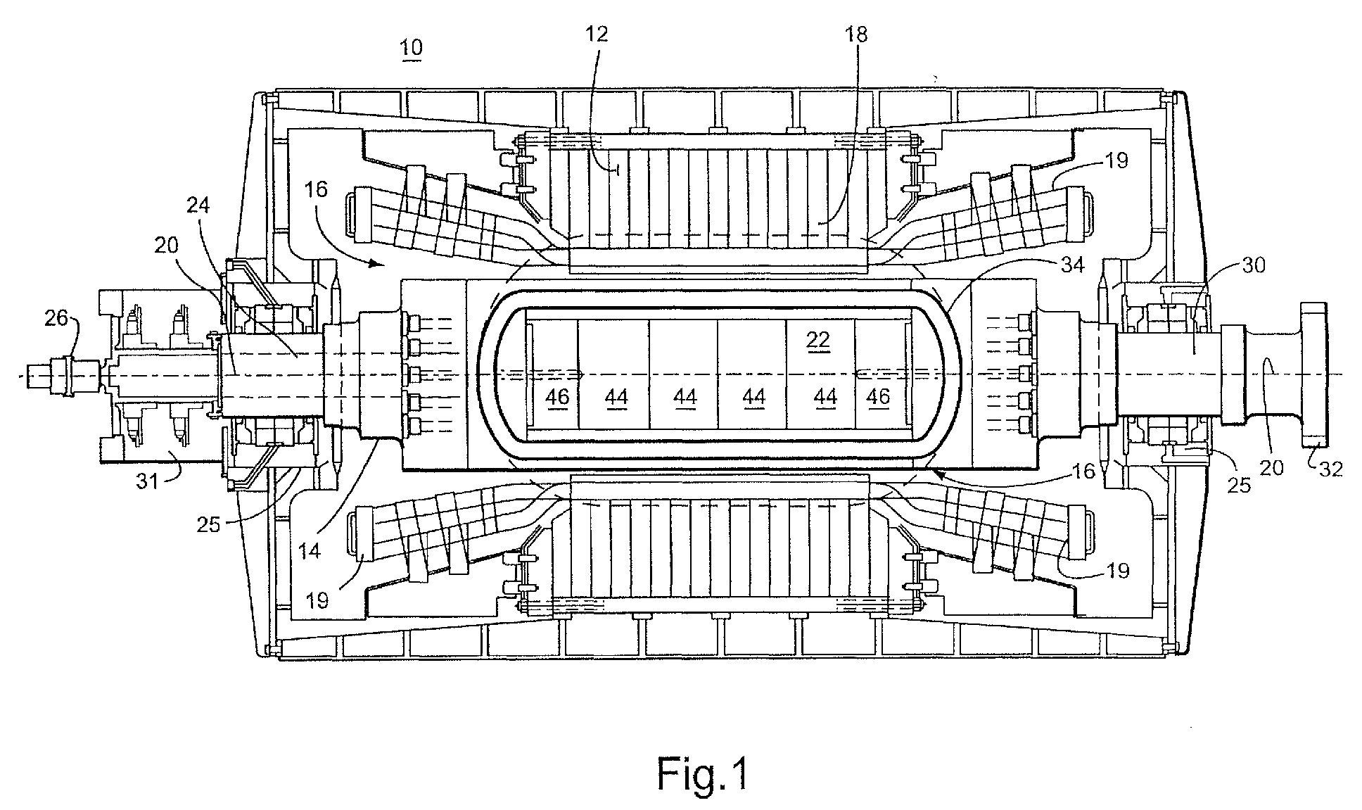
- FIGURE 1 shows an exemplary synchronous generator machine 10 having a stator 12 and a rotor 14.
- the rotor includes field winding coils that fit inside the cylindrical rotor cavity 16 of the stator.
- the rotor fits inside the rotor cavity of the stator.
- a magnetic field 18 (illustrated by dotted lines) generated by the rotor and rotor coils moves/rotates through the stator and creates an electrical current in the windings of the stator coils 19. This current is output by the generator as electrical power.
- the rotor 14 has a generally longitudinally-extending axis 20 and a generally solid, multi-piece rotor core 22.
- the rotor core is an assembly of axially-aligned end core sections 44 and middle core sections 46.
- the core 22 has high magnetic permeability, and is usually made of a ferromagnetic material, such as iron. In a low power density superconducting machine, the iron core of the rotor is used to reduce the magnetomotive force (MMF), and, thus, minimize the amount of superconducting (SC) coil wire needed for the coil winding.
- MMF magnetomotive force
- the rotor 14 supports at least one longitudinally-extending, racetrack-shaped, high-temperature superconducting (HTS) field winding assembly 33 having an HTS winding (See Fig. 2).
- the HTS field coil winding may be alternatively a saddle-shape or have some other shape that is suitable for a particular HTS rotor design.
- a rotor field assembly and coil support is disclosed here for a racetrack SC field winding.
- the rotor core assembly and coil support may be adapted for winding configurations other than a racetrack field winding mounted on a solid rotor core.
- the rotor includes a pair of end shafts 24, 30 that are supported by bearings 25.
- the end shafts may be coupled to external devices.
- one of the end shafts 24 has a cryogen transfer coupling 26 to a source of cryogenic cooling fluid used to cool the SC field windings in the rotor.
- the cryogen transfer coupling 26 includes a stationary segment coupled to a source of cryogen cooling fluid and a rotating segment which provides cooling fluid to the HTS winding.
- This end 24 of the rotor may also include a collector 31 for electrically connecting to the rotating SC field winding.
- the opposite end shaft 30 of the rotor may be driven by a power turbine coupling 32.
- FIGURE 2 shows an exemplary HTS racetrack field winding assembly 33 comprising a field coil winding 34 and a series of tension bars 35 (the coil support) extending between opposite sides of the winding.
- the winding assembly 33 is fabricated with the field winding 34 and tension bars 35 before the assembly 33 is inserted into the rotor core.
- the tension bars support the field coil windings with respect to the centrifugal forces that act on the windings as the rotor spins during operation. Accordingly, the tension bars are attached to the windings by a winding housing 36 (as shown in FIGURE 8). The housing and tension bars restrain the expansion of the field coil winding 34 that would otherwise occur with the tension bars 35.
- the SC field windings 34 of the rotor includes a high temperature superconducting (SC) winding 34.
- SC high temperature superconducting
- Each SC winding includes a high temperature superconducting conductor, such as a BSCCO (Bi x Sr x Ca x Cu x O x ) conductor wires laminated in a solid epoxy impregnated winding composite.
- BSCCO Bi x Sr x Ca x Cu x O x
- SC wire is brittle and easy to be damaged.
- the SC winding is typically layer wound SC tape that is epoxy impregnated.
- the SC tape is wrapped in a precision winding form to attain close dimensional tolerances.
- the tape is wound around in a helix to form the racetrack SC winding 34.
- racetrack winding The dimensions of the racetrack winding are dependent on the dimensions of the rotor core.
- each racetrack SC winding encircles the magnetic poles of the rotor core, and is parallel to the rotor axis.
- the field windings are continuous around the racetrack.
- the SC windings form a resistance free electrical current path around the rotor core and between the magnetic poles of the core.
- the winding has electrical contacts 41 that electrically connect the winding to the collector 31.
- Fluid passages 38 for cryogenic cooling fluid are included in the field winding 34. These passages may extend around an outside edge of the SC winding 34.
- the passageways provide cryogenic cooling fluid to the porous winding and remove heat from the winding.
- the cooling fluid maintains the low temperatures, e.g., 27K, in the SC field winding needed to promote superconducting conditions, including the absence of electrical resistance in the winding.
- the cooling passages have an input and output fluid ports 39 at one end of the rotor core. These fluid (gas) ports 39 connect the cooling passages 38 on the SC winding to the cryogen transfer coupling 26.
- Each HTS racetrack field winding 34 has a pair of generally straight side portions 40 parallel to a rotor axis 20, and a pair of end portions 42 that are perpendicular to the rotor axis.
- the side portions of the field coil winding are subjected to the greatest centrifugal stresses. Accordingly, the side portions are supported by the tension bars and housing. These bars and housing form a winding support system that counteract the centrifugal forces that act on the winding.
- FIGURE 3 is a schematic diagram of a multi-piece rotor core 22 with the winding assembly 33, including the racetrack superconducting coil field winding 34 and tension bars 35.
- the iron core is made of multiple core sections, which are generally several middle sections 44 and a pair of end sections 46. Each of the core sections have a semi-rectangular shape (see Fig. 7) with a pair of opposite flat sides 50 and a pair of opposite arc-shaped sides 52.
- the middle core sections 44 have a generally "T" shape in cross sections, except for the two end sections (compare Figures 5 and 6).
- the end sections 46 have a generally L-shaped cross section.
- the sections of the rotor core are assembled around the winding assembly 33.
- the narrow head 45 of each middle section slides between adjacent support bars 35 in the winding assembly.
- the narrow head of the end rotor core sections 46 slide between a tension bar 35 and an end 42 of the coil winding 34.
- Each of the core sections has at least one tension rod slot 53 (middle sections 44 have a pair of opposite slots) which when mated with the slot in an opposite core forms an aperture 55 for a tension bar 35.
- the assembly of rotor core sections permits integrating a fully assembled winding assembly 33 (which includes, for example, field winding 34 and tension bars 35) into the rotor core.
- the core sections 44, 46 may be iron core forgings.
- the rotor core sections are assembled through rabbit fits for concentricity and alignment.
- Each core section has at least one boss 54 (middle sections have a pair of opposing bosses) that fit into a slot 56 on an adjacent core section.
- the boss-slot connection between the core sections aligns the core sections in the rotor core.
- tie-rods 58 extend laterally through rod holes 60 along the length of the rotor core. The tie rods have a nut or other faster at each end and hold the core sections together in compression.
- a vacuum housing 64 may be formed over the field winding 34, once the rotor core sections have been assembled around the winding assembly. A vacuum around the winding facilitates the superconducting characteristics of the winding. The vacuum housing provides a vacuum over the entire race-track shape of the coil winding.
Landscapes
- Engineering & Computer Science (AREA)
- Power Engineering (AREA)
- Manufacturing & Machinery (AREA)
- Superconductive Dynamoelectric Machines (AREA)
- Insulation, Fastening Of Motor, Generator Windings (AREA)
- Iron Core Of Rotating Electric Machines (AREA)
- Manufacture Of Motors, Generators (AREA)
Abstract
Description
- 2. In a rotor as in clause 1 wherein said plurality of rotor core sections are axially aligned with an axis of said rotor core.
- 3. In a rotor as in clause 1 wherein said rotor core sections include opposite end core sections (42) and at least one middle core section (44).
- 4. In a rotor as in clause 3 wherein said end core sections have a generally L-shaped cross section, and said at least one middle core section has a generally T-shaped cross section.
- 5. In a rotor as in clause 3 wherein at least one middle core section (44) has a cross-sectional shape with a narrow head (45), where the head fits between a pair of bars of said winding supports.
- 6. In a rotor as in clause 5 wherein the at least one rotor core section has a wide region separated from the narrow head by a slot for the winding support.
- 7. In a rotor as in clause 1 further comprising at least one tie rod (58) extending through said plurality of rotor core sections and securing said core sections together.
- 8. In a rotor as in clause 1 further comprising a vacuum housing over said field coil winding.
- 9. In a rotor as in clause 1 wherein said core sections are iron.
- 10. In a rotor as in clause 1 wherein said core sections are iron forgings.
- 11. A rotor core (22) and winding assembly (33) comprising:
- separable rotor core sections (42, 44) assembled around the winding assembly to form said rotor core, where said core sections are axially aligned in said rotor core, and
- said winding assembly including a pre-assembled superconducting field winding (34) and a winding support (35), wherein the winding support extends through said rotor core.
Claims (10)
- A rotor in a synchronous machine (10),comprising:a superconducting field winding assembly (33) having a coil winding (34) and at least one winding support (35) extending between opposite sides of the winding, anda rotor core (22) formed of a plurality of rotor core sections (42, 44), each of said core sections having a slot (56) to receive said winding support.
- A rotor as in claim 1 wherein said plurality of rotor core sections are axially aligned with an axis of said rotor core.
- A rotor as in claim 1 wherein said rotor core sections include opposite end core sections (42) and at least one middle core section (44).
- A rotor as in claim 3 wherein said end core sections have a generally L-shaped cross section, and said at least one middle core section has a generally T-shaped cross section.
- A rotor as in claim 3 wherein at least one middle core section (44) has a cross-sectional shape with a narrow head (45), where the head fits between a pair of bars of said winding supports.
- A rotor as in claim 1 further comprising a vacuum housing over said field coil winding.
- A rotor core (22) and winding assembly (33) comprising:separable rotor core sections (42, 44) assembled around the winding assembly to form said rotor core, where said core sections are axially aligned in said rotor core, andsaid winding assembly including a pre-assembled superconducting field winding (34) and a winding support (35), wherein the winding support extends through said rotor core.
- A rotor as in claim 11 wherein said rotor core sections include opposite end core sections (42) and at least one middle core section (44).
- A method for assembling a rotor core (22) around a superconducting field coil winding assembly (33) comprising the steps of:a. fabricating said field coil winding assembly by assembling a field coil winding (34) and a coil support (35) prior to assembly of the rotor core,b. inserting a portion of each of a plurality of rotor core sections (44, 46) partially through said coil winding,c. assembling the plurality of rotor core sections around said coil support, andd. securing the assembly of rotor core sections.
- A method for assembling a rotor core as in claim 20 wherein the insertion of a portion of each of a plurality of rotor core sections includes inserting a narrow head (45) of one of said rotor core sections between adjacent bars (35) of the coil support.
Applications Claiming Priority (2)
| Application Number | Priority Date | Filing Date | Title |
|---|---|---|---|
| US09/935,735 US6795720B2 (en) | 2001-08-24 | 2001-08-24 | High temperature superconducting synchronous rotor coil having multi-piece rotor core |
| US935735 | 2001-08-24 |
Publications (3)
| Publication Number | Publication Date |
|---|---|
| EP1289104A2 true EP1289104A2 (en) | 2003-03-05 |
| EP1289104A3 EP1289104A3 (en) | 2004-09-22 |
| EP1289104B1 EP1289104B1 (en) | 2008-04-30 |
Family
ID=25467573
Family Applications (1)
| Application Number | Title | Priority Date | Filing Date |
|---|---|---|---|
| EP02255639A Expired - Lifetime EP1289104B1 (en) | 2001-08-24 | 2002-08-13 | High temperature superconducting synchronous rotor coil having multi-piece rotor core |
Country Status (14)
| Country | Link |
|---|---|
| US (2) | US6795720B2 (en) |
| EP (1) | EP1289104B1 (en) |
| JP (1) | JP4197415B2 (en) |
| KR (1) | KR100747927B1 (en) |
| CN (1) | CN100492828C (en) |
| AT (1) | ATE393979T1 (en) |
| BR (1) | BR0203373A (en) |
| CA (1) | CA2397128C (en) |
| CZ (1) | CZ302241B6 (en) |
| DE (1) | DE60226299T2 (en) |
| ES (1) | ES2304418T3 (en) |
| MX (1) | MXPA02008282A (en) |
| NO (1) | NO20024031L (en) |
| PL (1) | PL202621B1 (en) |
Families Citing this family (8)
| Publication number | Priority date | Publication date | Assignee | Title |
|---|---|---|---|---|
| US20060119193A1 (en) * | 2004-12-07 | 2006-06-08 | General Electric Company | Parallel wound superconducting coils for a synchronous |
| US20070239182A1 (en) * | 2006-04-03 | 2007-10-11 | Boston Scientific Scimed, Inc. | Thrombus removal device |
| DE102006027219A1 (en) * | 2006-06-12 | 2007-12-20 | Siemens Ag | Machine with uncooled rotor body and cooled rotor winding and associated holding and / or supporting device |
| US8346326B2 (en) | 2008-01-17 | 2013-01-01 | General Electric Company | Superconductive wire, processes of manufacture and uses thereof |
| US20100277136A1 (en) * | 2009-09-29 | 2010-11-04 | American Superconductor Corporation | Generator with ferromagnetic teeth |
| KR101372291B1 (en) | 2010-11-08 | 2014-03-11 | 가와사끼 쥬고교 가부시끼 가이샤 | Rotor core and superconducting rotating machine with the rotor core |
| US20120112571A1 (en) * | 2010-11-09 | 2012-05-10 | General Electric Company | Encapsulated stator assembly |
| DE102015211356A1 (en) * | 2015-06-19 | 2016-12-22 | Wobben Properties Gmbh | Method for producing a stator of a generator of a wind power plant, and form coil, winding structure and stator |
Family Cites Families (27)
| Publication number | Priority date | Publication date | Assignee | Title |
|---|---|---|---|---|
| DE2339772C3 (en) * | 1973-08-06 | 1979-10-04 | Kraftwerk Union Ag, 4330 Muelheim | Arrangement for fastening a superconducting excitation winding in the rotor of a turbo generator |
| US3983427A (en) * | 1975-05-14 | 1976-09-28 | Westinghouse Electric Corporation | Superconducting winding with grooved spacing elements |
| US3991333A (en) * | 1975-08-20 | 1976-11-09 | General Electric Company | Winding support structure for superconducting rotor |
| DE2741362C2 (en) * | 1977-09-12 | 1979-08-16 | Siemens Ag, 1000 Berlin Und 8000 Muenchen | Electric synchronous motor in turbo design |
| DE2854059A1 (en) * | 1978-12-14 | 1980-07-17 | Kraftwerk Union Ag | COOLING SYSTEM FOR RUNNERS OF ELECTRICAL MACHINES, ESPECIALLY FOR TURBOGENERATOR RUNNERS WITH SUPRAL-CONDUCTING FIELD DEVELOPMENT |
| JPS55125044A (en) * | 1979-03-19 | 1980-09-26 | Hitachi Ltd | Separated rotor |
| JPS566636A (en) * | 1979-06-29 | 1981-01-23 | Matsushita Electric Works Ltd | Method for assembling armature |
| JP2786330B2 (en) * | 1990-11-30 | 1998-08-13 | 株式会社日立製作所 | Superconducting magnet coil and curable resin composition used for the magnet coil |
| US5296773A (en) * | 1993-04-20 | 1994-03-22 | General Motors Corporation | Composite rotor for a synchronous reluctance machine |
| US5482919A (en) * | 1993-09-15 | 1996-01-09 | American Superconductor Corporation | Superconducting rotor |
| US5531015A (en) | 1994-01-28 | 1996-07-02 | American Superconductor Corporation | Method of making superconducting wind-and-react coils |
| US5548168A (en) * | 1994-06-29 | 1996-08-20 | General Electric Company | Superconducting rotor for an electrical machine |
| US5625548A (en) | 1994-08-10 | 1997-04-29 | American Superconductor Corporation | Control circuit for cryogenically-cooled power electronics employed in power conversion systems |
| US5672921A (en) | 1995-03-13 | 1997-09-30 | General Electric Company | Superconducting field winding assemblage for an electrical machine |
| US5532663A (en) | 1995-03-13 | 1996-07-02 | General Electric Company | Support structure for a superconducting coil |
| US5777420A (en) | 1996-07-16 | 1998-07-07 | American Superconductor Corporation | Superconducting synchronous motor construction |
| US6173577B1 (en) | 1996-08-16 | 2001-01-16 | American Superconductor Corporation | Methods and apparatus for cooling systems for cryogenic power conversion electronics |
| US5774032A (en) | 1996-08-23 | 1998-06-30 | General Electric Company | Cooling arrangement for a superconducting coil |
| US6066906A (en) | 1999-02-17 | 2000-05-23 | American Superconductor Corporation | Rotating machine having superconducting windings |
| US6140719A (en) | 1999-02-17 | 2000-10-31 | American Superconductor Corporation | High temperature superconducting rotor for a synchronous machine |
| US7211919B2 (en) | 1999-08-16 | 2007-05-01 | American Superconductor Corporation | Thermally-conductive stator support structure |
| US6169353B1 (en) * | 1999-09-28 | 2001-01-02 | Reliance Electric Technologies, Llc | Method for manufacturing a rotor having superconducting coils |
| US6693504B1 (en) | 2000-01-11 | 2004-02-17 | American Superconductor Corporation | Internal support for superconductor windings |
| US6879081B1 (en) | 2000-08-04 | 2005-04-12 | American Superconductor Corporation | Stator coil assembly for superconducting rotating machines |
| US6590308B2 (en) * | 2001-05-15 | 2003-07-08 | General Electric Company | High power density super-conducting electric machine |
| US6570292B2 (en) * | 2001-05-15 | 2003-05-27 | General Electric Company | High temperature super-conducting rotor coil support with split coil housing and assembly method |
| US6664672B2 (en) | 2001-07-13 | 2003-12-16 | American Superconductor Corporation | Enhancement of stator leakage inductance in air-core machines |
-
2001
- 2001-08-24 US US09/935,735 patent/US6795720B2/en not_active Expired - Fee Related
-
2002
- 2002-08-08 CA CA002397128A patent/CA2397128C/en not_active Expired - Fee Related
- 2002-08-13 AT AT02255639T patent/ATE393979T1/en active
- 2002-08-13 DE DE60226299T patent/DE60226299T2/en not_active Expired - Lifetime
- 2002-08-13 ES ES02255639T patent/ES2304418T3/en not_active Expired - Lifetime
- 2002-08-13 EP EP02255639A patent/EP1289104B1/en not_active Expired - Lifetime
- 2002-08-21 PL PL355594A patent/PL202621B1/en unknown
- 2002-08-22 CZ CZ20022866A patent/CZ302241B6/en not_active IP Right Cessation
- 2002-08-23 NO NO20024031A patent/NO20024031L/en not_active Application Discontinuation
- 2002-08-23 BR BR0203373-9A patent/BR0203373A/en not_active Application Discontinuation
- 2002-08-23 CN CNB021301921A patent/CN100492828C/en not_active Expired - Fee Related
- 2002-08-23 KR KR1020020050033A patent/KR100747927B1/en not_active Expired - Fee Related
- 2002-08-23 MX MXPA02008282A patent/MXPA02008282A/en active IP Right Grant
- 2002-08-23 JP JP2002242765A patent/JP4197415B2/en not_active Expired - Fee Related
-
2004
- 2004-07-01 US US10/880,652 patent/US7030535B2/en not_active Expired - Fee Related
Also Published As
| Publication number | Publication date |
|---|---|
| US6795720B2 (en) | 2004-09-21 |
| KR20030017420A (en) | 2003-03-03 |
| CA2397128A1 (en) | 2003-02-24 |
| US20050001507A1 (en) | 2005-01-06 |
| CN100492828C (en) | 2009-05-27 |
| ES2304418T3 (en) | 2008-10-16 |
| CN1407699A (en) | 2003-04-02 |
| NO20024031D0 (en) | 2002-08-23 |
| NO20024031L (en) | 2003-02-25 |
| EP1289104B1 (en) | 2008-04-30 |
| JP4197415B2 (en) | 2008-12-17 |
| CZ302241B6 (en) | 2011-01-05 |
| US20030038560A1 (en) | 2003-02-27 |
| PL355594A1 (en) | 2003-03-10 |
| CA2397128C (en) | 2008-03-25 |
| DE60226299T2 (en) | 2009-06-25 |
| ATE393979T1 (en) | 2008-05-15 |
| US7030535B2 (en) | 2006-04-18 |
| JP2003125573A (en) | 2003-04-25 |
| BR0203373A (en) | 2003-05-27 |
| KR100747927B1 (en) | 2007-08-08 |
| EP1289104A3 (en) | 2004-09-22 |
| CZ20022866A3 (en) | 2003-04-16 |
| MXPA02008282A (en) | 2004-12-13 |
| PL202621B1 (en) | 2009-07-31 |
| DE60226299D1 (en) | 2008-06-12 |
Similar Documents
| Publication | Publication Date | Title |
|---|---|---|
| US6794792B2 (en) | Cold structural enclosure for multi-pole rotor having super-conducting field coil windings. | |
| US6605886B2 (en) | High temperature superconductor synchronous rotor coil support insulator | |
| KR100900602B1 (en) | High temperature super-conducting synchronous rotor having an electromagnetic shield and method for assembly | |
| EP1261116B1 (en) | High Temperature Superconducting Synchronous Rotor Coil Support with Tension Rods | |
| US6803684B2 (en) | Super-conducting synchronous machine having rotor and a plurality of super-conducting field coil windings | |
| US6617714B2 (en) | High temperature super-conducting coils supported by an iron core rotor | |
| EP1289104B1 (en) | High temperature superconducting synchronous rotor coil having multi-piece rotor core | |
| US6590308B2 (en) | High power density super-conducting electric machine | |
| US6787967B2 (en) | High temperature super-conducting rotor coil support and coil support method |
Legal Events
| Date | Code | Title | Description |
|---|---|---|---|
| PUAI | Public reference made under article 153(3) epc to a published international application that has entered the european phase |
Free format text: ORIGINAL CODE: 0009012 |
|
| AK | Designated contracting states |
Designated state(s): AT BE BG CH CY CZ DE DK EE ES FI FR GB GR IE IT LI LU MC NL PT SE SK TR Kind code of ref document: A2 Designated state(s): AT BE BG CH CY CZ DE DK EE ES FI FR GB GR IE IT LI LU MC NL PT SE SK TR |
|
| AX | Request for extension of the european patent |
Extension state: AL LT LV MK RO SI |
|
| PUAL | Search report despatched |
Free format text: ORIGINAL CODE: 0009013 |
|
| AK | Designated contracting states |
Kind code of ref document: A3 Designated state(s): AT BE BG CH CY CZ DE DK EE ES FI FR GB GR IE IT LI LU MC NL PT SE SK TR |
|
| AX | Request for extension of the european patent |
Extension state: AL LT LV MK RO SI |
|
| 17P | Request for examination filed |
Effective date: 20050322 |
|
| AKX | Designation fees paid |
Designated state(s): AT BE BG CH CY CZ DE DK EE ES FI FR GB GR IE IT LI LU MC NL PT SE SK TR |
|
| 17Q | First examination report despatched |
Effective date: 20060912 |
|
| 17Q | First examination report despatched |
Effective date: 20060912 |
|
| GRAP | Despatch of communication of intention to grant a patent |
Free format text: ORIGINAL CODE: EPIDOSNIGR1 |
|
| GRAS | Grant fee paid |
Free format text: ORIGINAL CODE: EPIDOSNIGR3 |
|
| GRAA | (expected) grant |
Free format text: ORIGINAL CODE: 0009210 |
|
| AK | Designated contracting states |
Kind code of ref document: B1 Designated state(s): AT BE BG CH CY CZ DE DK EE ES FI FR GB GR IE IT LI LU MC NL PT SE SK TR |
|
| REG | Reference to a national code |
Ref country code: GB Ref legal event code: FG4D |
|
| REG | Reference to a national code |
Ref country code: CH Ref legal event code: NV Representative=s name: SERVOPATENT GMBH |
|
| REG | Reference to a national code |
Ref country code: CH Ref legal event code: EP |
|
| REG | Reference to a national code |
Ref country code: IE Ref legal event code: FG4D Free format text: LANGUAGE OF EP DOCUMENT: FRENCH |
|
| REF | Corresponds to: |
Ref document number: 60226299 Country of ref document: DE Date of ref document: 20080612 Kind code of ref document: P |
|
| REG | Reference to a national code |
Ref country code: CH Ref legal event code: NV Representative=s name: SERVOPATENT GMBH |
|
| REG | Reference to a national code |
Ref country code: SE Ref legal event code: TRGR |
|
| NLV1 | Nl: lapsed or annulled due to failure to fulfill the requirements of art. 29p and 29m of the patents act | ||
| REG | Reference to a national code |
Ref country code: ES Ref legal event code: FG2A Ref document number: 2304418 Country of ref document: ES Kind code of ref document: T3 |
|
| PG25 | Lapsed in a contracting state [announced via postgrant information from national office to epo] |
Ref country code: PT Free format text: LAPSE BECAUSE OF FAILURE TO SUBMIT A TRANSLATION OF THE DESCRIPTION OR TO PAY THE FEE WITHIN THE PRESCRIBED TIME-LIMIT Effective date: 20080930 Ref country code: FI Free format text: LAPSE BECAUSE OF FAILURE TO SUBMIT A TRANSLATION OF THE DESCRIPTION OR TO PAY THE FEE WITHIN THE PRESCRIBED TIME-LIMIT Effective date: 20080430 Ref country code: BG Free format text: LAPSE BECAUSE OF FAILURE TO SUBMIT A TRANSLATION OF THE DESCRIPTION OR TO PAY THE FEE WITHIN THE PRESCRIBED TIME-LIMIT Effective date: 20080730 Ref country code: NL Free format text: LAPSE BECAUSE OF FAILURE TO SUBMIT A TRANSLATION OF THE DESCRIPTION OR TO PAY THE FEE WITHIN THE PRESCRIBED TIME-LIMIT Effective date: 20080430 |
|
| ET | Fr: translation filed | ||
| PG25 | Lapsed in a contracting state [announced via postgrant information from national office to epo] |
Ref country code: DK Free format text: LAPSE BECAUSE OF FAILURE TO SUBMIT A TRANSLATION OF THE DESCRIPTION OR TO PAY THE FEE WITHIN THE PRESCRIBED TIME-LIMIT Effective date: 20080430 Ref country code: CZ Free format text: LAPSE BECAUSE OF FAILURE TO SUBMIT A TRANSLATION OF THE DESCRIPTION OR TO PAY THE FEE WITHIN THE PRESCRIBED TIME-LIMIT Effective date: 20080430 |
|
| PG25 | Lapsed in a contracting state [announced via postgrant information from national office to epo] |
Ref country code: SK Free format text: LAPSE BECAUSE OF FAILURE TO SUBMIT A TRANSLATION OF THE DESCRIPTION OR TO PAY THE FEE WITHIN THE PRESCRIBED TIME-LIMIT Effective date: 20080430 Ref country code: BE Free format text: LAPSE BECAUSE OF FAILURE TO SUBMIT A TRANSLATION OF THE DESCRIPTION OR TO PAY THE FEE WITHIN THE PRESCRIBED TIME-LIMIT Effective date: 20080430 |
|
| PLBE | No opposition filed within time limit |
Free format text: ORIGINAL CODE: 0009261 |
|
| STAA | Information on the status of an ep patent application or granted ep patent |
Free format text: STATUS: NO OPPOSITION FILED WITHIN TIME LIMIT |
|
| PG25 | Lapsed in a contracting state [announced via postgrant information from national office to epo] |
Ref country code: MC Free format text: LAPSE BECAUSE OF NON-PAYMENT OF DUE FEES Effective date: 20080831 |
|
| 26N | No opposition filed |
Effective date: 20090202 |
|
| PG25 | Lapsed in a contracting state [announced via postgrant information from national office to epo] |
Ref country code: EE Free format text: LAPSE BECAUSE OF FAILURE TO SUBMIT A TRANSLATION OF THE DESCRIPTION OR TO PAY THE FEE WITHIN THE PRESCRIBED TIME-LIMIT Effective date: 20080430 |
|
| REG | Reference to a national code |
Ref country code: IE Ref legal event code: MM4A |
|
| PG25 | Lapsed in a contracting state [announced via postgrant information from national office to epo] |
Ref country code: IE Free format text: LAPSE BECAUSE OF NON-PAYMENT OF DUE FEES Effective date: 20080813 |
|
| PG25 | Lapsed in a contracting state [announced via postgrant information from national office to epo] |
Ref country code: LU Free format text: LAPSE BECAUSE OF NON-PAYMENT OF DUE FEES Effective date: 20080813 Ref country code: CY Free format text: LAPSE BECAUSE OF FAILURE TO SUBMIT A TRANSLATION OF THE DESCRIPTION OR TO PAY THE FEE WITHIN THE PRESCRIBED TIME-LIMIT Effective date: 20080430 |
|
| PG25 | Lapsed in a contracting state [announced via postgrant information from national office to epo] |
Ref country code: TR Free format text: LAPSE BECAUSE OF FAILURE TO SUBMIT A TRANSLATION OF THE DESCRIPTION OR TO PAY THE FEE WITHIN THE PRESCRIBED TIME-LIMIT Effective date: 20080430 |
|
| PG25 | Lapsed in a contracting state [announced via postgrant information from national office to epo] |
Ref country code: GR Free format text: LAPSE BECAUSE OF FAILURE TO SUBMIT A TRANSLATION OF THE DESCRIPTION OR TO PAY THE FEE WITHIN THE PRESCRIBED TIME-LIMIT Effective date: 20080731 |
|
| PGFP | Annual fee paid to national office [announced via postgrant information from national office to epo] |
Ref country code: CH Payment date: 20140827 Year of fee payment: 13 Ref country code: DE Payment date: 20140827 Year of fee payment: 13 |
|
| PGFP | Annual fee paid to national office [announced via postgrant information from national office to epo] |
Ref country code: GB Payment date: 20140827 Year of fee payment: 13 Ref country code: FR Payment date: 20140818 Year of fee payment: 13 Ref country code: SE Payment date: 20140827 Year of fee payment: 13 Ref country code: ES Payment date: 20140826 Year of fee payment: 13 |
|
| PGFP | Annual fee paid to national office [announced via postgrant information from national office to epo] |
Ref country code: IT Payment date: 20140825 Year of fee payment: 13 |
|
| PGFP | Annual fee paid to national office [announced via postgrant information from national office to epo] |
Ref country code: AT Payment date: 20150721 Year of fee payment: 14 |
|
| REG | Reference to a national code |
Ref country code: DE Ref legal event code: R119 Ref document number: 60226299 Country of ref document: DE |
|
| REG | Reference to a national code |
Ref country code: SE Ref legal event code: EUG |
|
| REG | Reference to a national code |
Ref country code: CH Ref legal event code: PL |
|
| GBPC | Gb: european patent ceased through non-payment of renewal fee |
Effective date: 20150813 |
|
| PG25 | Lapsed in a contracting state [announced via postgrant information from national office to epo] |
Ref country code: LI Free format text: LAPSE BECAUSE OF NON-PAYMENT OF DUE FEES Effective date: 20150831 Ref country code: CH Free format text: LAPSE BECAUSE OF NON-PAYMENT OF DUE FEES Effective date: 20150831 Ref country code: IT Free format text: LAPSE BECAUSE OF NON-PAYMENT OF DUE FEES Effective date: 20150813 |
|
| PG25 | Lapsed in a contracting state [announced via postgrant information from national office to epo] |
Ref country code: SE Free format text: LAPSE BECAUSE OF NON-PAYMENT OF DUE FEES Effective date: 20150814 |
|
| REG | Reference to a national code |
Ref country code: FR Ref legal event code: ST Effective date: 20160429 |
|
| PG25 | Lapsed in a contracting state [announced via postgrant information from national office to epo] |
Ref country code: GB Free format text: LAPSE BECAUSE OF NON-PAYMENT OF DUE FEES Effective date: 20150813 Ref country code: DE Free format text: LAPSE BECAUSE OF NON-PAYMENT OF DUE FEES Effective date: 20160301 |
|
| PG25 | Lapsed in a contracting state [announced via postgrant information from national office to epo] |
Ref country code: FR Free format text: LAPSE BECAUSE OF NON-PAYMENT OF DUE FEES Effective date: 20150831 |
|
| REG | Reference to a national code |
Ref country code: ES Ref legal event code: FD2A Effective date: 20160927 |
|
| PG25 | Lapsed in a contracting state [announced via postgrant information from national office to epo] |
Ref country code: ES Free format text: LAPSE BECAUSE OF NON-PAYMENT OF DUE FEES Effective date: 20150814 |
|
| REG | Reference to a national code |
Ref country code: AT Ref legal event code: MM01 Ref document number: 393979 Country of ref document: AT Kind code of ref document: T Effective date: 20160813 |
|
| PG25 | Lapsed in a contracting state [announced via postgrant information from national office to epo] |
Ref country code: AT Free format text: LAPSE BECAUSE OF NON-PAYMENT OF DUE FEES Effective date: 20160813 |