EP1289051A1 - Antenna element and portable information terminal - Google Patents
Antenna element and portable information terminal Download PDFInfo
- Publication number
- EP1289051A1 EP1289051A1 EP00935513A EP00935513A EP1289051A1 EP 1289051 A1 EP1289051 A1 EP 1289051A1 EP 00935513 A EP00935513 A EP 00935513A EP 00935513 A EP00935513 A EP 00935513A EP 1289051 A1 EP1289051 A1 EP 1289051A1
- Authority
- EP
- European Patent Office
- Prior art keywords
- antenna
- unit
- antenna element
- portable telephone
- antenna unit
- Prior art date
- Legal status (The legal status is an assumption and is not a legal conclusion. Google has not performed a legal analysis and makes no representation as to the accuracy of the status listed.)
- Withdrawn
Links
Images







Classifications
-
- H—ELECTRICITY
- H01—ELECTRIC ELEMENTS
- H01Q—ANTENNAS, i.e. RADIO AERIALS
- H01Q9/00—Electrically-short antennas having dimensions not more than twice the operating wavelength and consisting of conductive active radiating elements
- H01Q9/04—Resonant antennas
- H01Q9/30—Resonant antennas with feed to end of elongated active element, e.g. unipole
-
- H—ELECTRICITY
- H01—ELECTRIC ELEMENTS
- H01Q—ANTENNAS, i.e. RADIO AERIALS
- H01Q1/00—Details of, or arrangements associated with, antennas
- H01Q1/12—Supports; Mounting means
- H01Q1/22—Supports; Mounting means by structural association with other equipment or articles
- H01Q1/24—Supports; Mounting means by structural association with other equipment or articles with receiving set
- H01Q1/241—Supports; Mounting means by structural association with other equipment or articles with receiving set used in mobile communications, e.g. GSM
- H01Q1/242—Supports; Mounting means by structural association with other equipment or articles with receiving set used in mobile communications, e.g. GSM specially adapted for hand-held use
- H01Q1/243—Supports; Mounting means by structural association with other equipment or articles with receiving set used in mobile communications, e.g. GSM specially adapted for hand-held use with built-in antennas
-
- H—ELECTRICITY
- H01—ELECTRIC ELEMENTS
- H01Q—ANTENNAS, i.e. RADIO AERIALS
- H01Q1/00—Details of, or arrangements associated with, antennas
- H01Q1/12—Supports; Mounting means
- H01Q1/22—Supports; Mounting means by structural association with other equipment or articles
- H01Q1/24—Supports; Mounting means by structural association with other equipment or articles with receiving set
- H01Q1/241—Supports; Mounting means by structural association with other equipment or articles with receiving set used in mobile communications, e.g. GSM
- H01Q1/242—Supports; Mounting means by structural association with other equipment or articles with receiving set used in mobile communications, e.g. GSM specially adapted for hand-held use
- H01Q1/243—Supports; Mounting means by structural association with other equipment or articles with receiving set used in mobile communications, e.g. GSM specially adapted for hand-held use with built-in antennas
- H01Q1/244—Supports; Mounting means by structural association with other equipment or articles with receiving set used in mobile communications, e.g. GSM specially adapted for hand-held use with built-in antennas extendable from a housing along a given path
-
- H—ELECTRICITY
- H01—ELECTRIC ELEMENTS
- H01Q—ANTENNAS, i.e. RADIO AERIALS
- H01Q1/00—Details of, or arrangements associated with, antennas
- H01Q1/36—Structural form of radiating elements, e.g. cone, spiral, umbrella; Particular materials used therewith
-
- H—ELECTRICITY
- H01—ELECTRIC ELEMENTS
- H01Q—ANTENNAS, i.e. RADIO AERIALS
- H01Q1/00—Details of, or arrangements associated with, antennas
- H01Q1/36—Structural form of radiating elements, e.g. cone, spiral, umbrella; Particular materials used therewith
- H01Q1/38—Structural form of radiating elements, e.g. cone, spiral, umbrella; Particular materials used therewith formed by a conductive layer on an insulating support
-
- H—ELECTRICITY
- H01—ELECTRIC ELEMENTS
- H01Q—ANTENNAS, i.e. RADIO AERIALS
- H01Q11/00—Electrically-long antennas having dimensions more than twice the shortest operating wavelength and consisting of conductive active radiating elements
- H01Q11/02—Non-resonant antennas, e.g. travelling-wave antenna
- H01Q11/08—Helical antennas
Definitions
- the present invention relates to an antenna element and a portable information terminal, particularly to an antenna element used in a portable telephone and a portable telephone employing such an antenna element.
- the monopole antenna and helical antenna attached so as to extend in the longitudinal direction of a casing are known.
- the impedance of such antenna elements differs from the impedance of the radio transmitter-receiver in the portable telephone. Therefore, the impedance must be matched.
- a matching circuit to match the impedance is provided between the radio transmitter-receiver and the antenna element in the conventional portable telephone.
- the matching circuit is configured by a lumped constant element such as coils and capacitors.
- a lumped constant element such as coils and capacitors.
- a vertically polarized wave is used as the wave to transmit information. This is due to the fact that the wave diffraction effect is great in vertical polarization.
- the wave can travel around a construction to arrive at the backside thereof so that a wave can be transmitted/received even to/from an area blocked by a construction.
- the antenna element of a portable telephone is designed so as to extend substantially perpendicular in a conversation mode since a vertically polarized wave is transmitted/received as the main wave of polarization, it is known that the portable telephone terminal is generally tilted 60° on an average to the zenith angle when used. Accordingly, there is the problem that the main wave of polarization is reversed to become a horizontally polarized wave during actual conversation.
- the present invention is directed to solve such a problem.
- An object of the present invention is to provide an antenna element and portable information terminal reduced in electrical signal loss and with high efficiency.
- Another object of the present invention is to provide an antenna element and portable information terminal of high gain in conversation.
- An antenna element includes a first antenna unit formed to extend in one direction, and a second antenna unit having an electrical length of substantially ( ⁇ /2) ⁇ A (A is an integer), coupled to the first antenna unit and extending in a direction substantially orthogonal to the extending direction of the first antenna unit.
- the first antenna unit functions as the conventional matching circuit. Since this first antenna unit can be configured without using a lumped constant element, no loss is generated here. Therefore, the antenna efficiency can be improved. Since the second antenna unit extends substantially orthogonal to the extending direction of the first antenna element, any one of the first and second antenna units can transmit/receive a vertically polarized wave whereas the other can transmit/receive a horizontally polarized wave. Accordingly, a vertically polarized wave and a horizontally polarized wave can be transmitted/received regardless of the orientation of the antenna element. Thus, the antenna element has the gain in a conversation mode improved.
- the electrical length of the first antenna unit is approximately ( ⁇ /4) + ( ⁇ /2) ⁇ B (B is an integer).
- the first antenna unit is equal to the so-called ⁇ /4 antenna to reliably transmit/receive a vertically or horizontally polarized wave at the first antenna unit.
- the first antenna unit includes at least one type of antenna selected from the group consisting of a plate antenna, a monopole antenna, a helical antenna, a meander line antenna and a zigzag antenna.
- the second antenna unit includes a line antenna.
- the line antenna includes at least one type of antenna selected from the group consisting of a monopole antenna and a helical antenna.
- the antenna element further includes a substrate having a conductive surface.
- the first antenna unit is provided on the surface of the substrate with a dielectric therebetween.
- the second antenna unit is provided so as to extend from the substrate.
- the first antenna unit is provided on the substrate with a dielectric therebetween here, the wavelength of the electromagnetic wave progressing the first antenna unit can be reduced. As a result, the length of the first antenna unit can be reduced to allow a smaller antenna element. Since the second antenna unit is provided so as to extend from the substrate, a wave can be transmitted/received reliably without the second antenna unit being affected by the substrate.
- the first antenna unit and the second antenna unit are attached in order to a feeding point.
- a portable information terminal includes a main unit case and an antenna element.
- the antenna element includes a first antenna unit disposed in the main unit case and extending in one direction, and a second antenna unit arranged projectable from the main unit case, having an electrical length of approximately ( ⁇ /2) ⁇ A (A is an integer) coupled to the first antenna unit and extending substantially orthogonal to the extending direction of the first antenna unit.
- the first antenna unit functions to match the impedance between the second antenna unit and a radio transmitter-receiver unit. Since the first antenna unit can be configured without using a lumped constant element, any loss at this region can be prevented. Since the second antenna unit extends in a direction substantially orthogonal to a first antenna unit, any one of the first antenna unit and the second antenna unit can receive/transmit a vertically polarized wave whereas the other can transmit/receive a horizontally polarized wave irrespective of the orientation of the portable telephone. As a result, a portable information terminal of a high gain in a conversation mode is provided.
- the second antenna unit includes a third antenna unit having an electrical length of approximately ( ⁇ /2) ⁇ C (C is an integer), and a fourth antenna unit coupled to the third antenna unit and having an electrical length of approximately ( ⁇ /2) ⁇ D (D is an integer).
- the third and fourth antenna units project from the main unit case.
- the third antenna unit projects from the main unit case whereas the fourth antenna unit is located in the main unit case.
- the third antenna unit having an electrical length of approximately ( ⁇ /2) ⁇ C and the fourth antenna unit having an electrical length of approximately ( ⁇ /2) ⁇ D project from the main unit case. Therefore, the electrical length of the projecting antenna is equal to an integer multiple of ⁇ /2. Accordingly, a wave can be reliably transmitted/received by this antenna. Since the third antenna unit having an electrical length of approximately ( ⁇ /2) ⁇ C projects from the main case even when the antenna element is in an accommodated state, a wave can be reliably transmitted/received by the antenna.
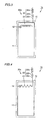
- Fig. 1 shows a portable telephone according to a first embodiment of the present invention with the antenna pulled out.
- a portable telephone 1a includes a main unit case 10 and an antenna element 20a.
- Antenna element 20a includes a meander line antenna 21 which is the first antenna unit, formed to extend in one direction, a second antenna unit 22 with an electrical length of approximately ( ⁇ /2) ⁇ A (A is an integer), coupled to meander line antenna 21, and extending substantially orthogonal to the extending direction of meander line antenna 21, and a metal substrate 11 serving as a substrate supporting meander line antenna 21 and second antenna unit 22.
- Metal substrate 11 is formed having a metal of high conductivity such as copper deposited on a predetermined insulation substrate.
- the metal formed on the insulation substrate may be replaced with another that has a conductivity similar to that of copper.
- Metal substrate 11 extends in the longitudinal direction, and is substantially rectangle in shape.
- Second antenna unit 22 is provided so as to extend along the longer side of metal substrate 11.
- Meander line antenna 21 is provided so as to extend along the shorter side of metal substrate 11.
- Metal substrate 11 is disposed in main unit case 10 of the portable telephone.
- Metal substrate 11 is of a thin plate configuration with a radio transmitter-receiver not shown provided at the surface.
- the radio transmitter-receiver is connected to meander line antenna 21 via a feeding point 12.
- Meander line antenna 21 which is the first antenna unit is provided in the direction of the shorter side of metal substrate 11, i.e., in the direction from left to right in Fig. 1. An airspace is provided between meander line antenna 21 and the surface of metal substrate 11. A solid dielectric may be provided between meander line antenna 21 and metal substrate 11 to hold meander line antenna 21. Meander line antenna 21 has one end connected to feeding point 21 and the other end connected to second antenna unit 22. The electrical length of meander line antenna 21 is ⁇ /4. The electrical length of meander line 21 can be also set to ( ⁇ /4) + ( ⁇ /2) ⁇ B (B is an integer).
- Second antenna unit 22 is provided so as to be connected to meander line antenna 21.
- Second antenna unit 22 includes a helical antenna 22a, an insulator 22b and a monopole antenna 22c.
- Helical antenna 22a and monopole antenna 22c are line antennas with insulator 22b therebetween.
- Insulator 22b is formed of, for example, ABS (alkyl benzene sulfonic acid) resin.
- Helical antenna 22a constitutes the third antenna, and has an electrical length of ⁇ /2.
- the electrical length of helical antenna 22a can be set to ( ⁇ /2) ⁇ C (C is an integer).
- Monopole antenna 22c constitutes the fourth antenna unit, and has an electrical length of ⁇ /2.
- the electrical length of monopole antenna 22c can be also set to ( ⁇ /2) ⁇ D (D is an integer).
- helical antenna 22a and monopole antenna 22c project from main unit case 10.
- Meander line antenna 21 is accommodated in main unit case 10.
- Meander line antenna 21 and second antenna unit 22 extend substantially orthogonal to form an L shape antenna.
- Meander line antenna 21 functions to match the impedance between second antenna unit 22 and a radio transmitter-receiver not shown connected to feeding point 12.
- second antenna unit 22 extends in a direction that is substantially perpendicular whereas the first antenna unit extends in a direction that is substantially horizontal.
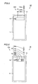
- Fig. 2 shows the state where the antenna is stored in the portable telephone of the first embodiment.
- monopole antenna 22c and insulator 22b are located in main unit case 10 when the antenna is in an accommodated state.
- helical antenna 22a is configured so as to project from main unit case 10.
- helical antenna 22a functions as the so-called ⁇ /2 antenna.
- a matching circuit formed of a lumped constant element is not required. Therefore, any occurrence of a loss in the lumped constant element can be prevented. Thus, a portable telephone and antenna element of high efficiency can be provided.
- Second antenna unit 22 extends in a direction orthogonal to meander line antenna 21. Therefore, when portable telephone 1a is held so that second antenna unit 22 extends in the perpendicular direction, second antenna unit 22 transmits/receives a vertically polarized wave whereas meander line antenna 21 transmits/receives a horizontally polarized wave. In contrast, when portable telephone 1a is held so that second antenna unit 22 extends in the horizontal direction, second antenna unit 22 transmits/receives a horizontally polarized wave whereas meander line antenna 21 transmits/receives a vertically polarized wave. Since a vertically polarized wave and horizontally polarized wave can be transmitted/received irrespective of the orientation of portable telephone 1a, the gain in a conversation mode can be improved.
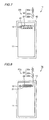
- Fig. 3 shows a portable telephone according to a second embodiment of the present invention.
- a portable telephone 1b according to the second embodiment includes an antenna element 20b.
- Antenna element 20b differs from antenna element 20a shown in Figs. 1 and 2 in that the first antenna unit is formed of a helical antenna 23.
- Helical antenna 23 has an electrical length of approximately ( ⁇ /4) + ( ⁇ /2) ⁇ B (B is an integer).
- Portable telephone 1b and antenna element 20b configured as described above provides advantageous effects similar to those of portable telephone 1a and antenna element 20a of Figs. 1 and 2 of the first embodiment. Since the physical length of the first antenna can be reduced by using helical antenna 23 as the first antenna unit, portable telephone 1b can be reduced in size.
- Fig. 4 shows a portable telephone according to a third embodiment of the present invention.
- portable telephone 1c of the third embodiment has an antenna element 20c.
- Antenna element 20c differs from antenna element 20a of Figs. 1 and 2 in that the first antenna unit is formed of a zigzag antenna 24.
- the electrical length of zigzag antenna 24 is approximately ( ⁇ /4) + ( ⁇ /2) ⁇ B (B is an integer).
- Portable telephone 1c and antenna element 20c configured as described above provide advantageous effects similar to those of portable telephone 1a and antenna element 20a of the first embodiment.
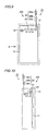
- Fig. 5 shows a portable telephone according to a fourth embodiment of the present invention.
- a portable telephone 1d of the fourth embodiment includes an antenna element 20d.
- Antenna element 20d differs from antenna element 20a of Figs. 1 and 2 in that the first antenna unit is formed of a plate antenna 25.
- Plate antenna 25a is formed to have a short side that extends along second antenna unit 22, and a long side. The long side is formed to extend in a direction substantially orthogonal to second antenna unit 22.
- the electrical length of plate antenna 25 is approximately ( ⁇ /4) + ( ⁇ /2) ⁇ B (B is an integer).
- Portable telephone 1d and antenna element 20d configured as described above provide advantageous effects similar to those of portable telephone 1a and antenna element 20a of Figs. 1 and 2. Furthermore, by using plate antenna 25 as the first antenna unit, the current flow in the first antenna unit can be deconcentrated. Accordingly, degradation in the gain of the first antenna can be prevented.
- Fig. 6 shows a portable telephone according to a fifth embodiment of the present invention.
- a portable telephone 1e of the fifth embodiment includes an antenna unit 20e.
- Antenna unit 20e includes a first antenna unit 26.
- the difference from antenna element 20a of Figs. 1 and 2 lies in that first antenna element 26 is formed of a meander line antenna 26a and a plate antenna 26b.
- Meander line antenna 26a is disposed at both ends of first antenna unit 26.
- Plate antenna 26b is located substantially at the center between meander line antennas 26a.
- the electrical length of first antenna unit 26 is approximately ( ⁇ /4) + ( ⁇ /2) ⁇ B (B is an integer).
- Portable telephone 1e and antenna element 20e configured as described above provide advantageous effects similar to those of portable telephone 1a and antenna element 20a of Figs. 1 and 2 of the first embodiment. Furthermore, by disposing plate antenna 26b at the center of first antenna unit 26 exhibiting the greatest current distribution, degradation of the gain when one's finger is placed on first antenna unit 26 can be reduced.
- Fig. 7 shows a portable telephone according to a sixth embodiment of the present invention.
- a portable telephone 1f according to the sixth embodiment of the present invention includes an antenna element 20f.
- a meander line antenna 21 which is the first antenna unit of antenna element 20f is disposed on a dielectric 31.
- Dielectric 31 is formed of a material having a small dielectric dissipation factor (tan ⁇ ) and a high relative dielectric constant.
- dielectric 31 is formed of a ceramics type material (relative dielectric constant ⁇ 7-100), Teflon (relative dielectric constant ⁇ 2.1) and a resin based material (relative dielectric constant ⁇ 3.3) such as Vectra.
- meander line antenna 21 is provided on and along dielectric 31, meander line antenna 21 can be embedded in dielectric 31 instead. Furthermore, on dielectric 31 may be disposed helical antenna 23 of Fig. 3, zigzag antenna 24 of Fig. 4, plate antenna 25 of Fig. 5, and first antenna unit 26 of Fig. 6 having meander line antenna 26a and plate antenna 26b coupled.
- Portable telephone 1f and antenna element 20f configured as described above provide advantageous effects similar to those of portable telephone 1a and antenna element 20a shown in Figs. 1 and 2. Since meander line antenna 21 is mounted on dielectric 31 that has a high relative dielectric constant, the wavelength of the wave progressing meander line antenna 21 can be reduced. As a result, the size of meander line antenna 21 can be reduced. Accordingly, metal substrate 11 can be reduced in size, which in turn allows main unit case 10 configuring portable telephone 1f to be reduced in size.
- Fig. 8 shows a portable telephone according to a seventh embodiment of the present invention.
- a portable telephone 1g according to the seventh embodiment includes an antenna element 20g.
- Antenna element 20g has dielectric 31 disposed in helical antenna 23 which is the first antenna unit.
- Dielectric 31 is disposed in a core-like manner at the center of helical antenna 23 forming a coil.
- Dielectric 31 extends along the extending direction of helical antenna 23.
- the material forming dielectric 31 may be identical to that forming dielectric 31 of Fig. 7.
- Portable telephone 1g and antenna element 20g configured as described above provide advantageous effects similar to those of portable telephone 1f and antenna element 20f of Fig. 7.
- Fig. 9 shows a portable telephone according to an eighth embodiment of the present invention.
- Fig. 10 is a diagram of the portable telephone viewed from the direction indicated by arrow X in Fig. 9.
- a portable telephone 1h includes an antenna element 20h.
- Antenna element 20h includes a meander line antenna 21 as the first antenna unit.
- Meander line antenna 21 is located close to the surface of metal substrate 11 in the proximity of feeding point 12, and extends in a direction away from metal substrate 11 as a function of distance from feeding point 12. In other words, the distance between metal substrate 11 and meander line antenna 21 is relatively small in the proximity of feeding point 12 and relatively great at the area where meander line antenna 21 is connected to monopole antenna 22c.
- meander line antenna 21 is formed to extend in a direction farther away from metal substrate 11.
- a feeding point 12 is provided at the surface of metal substrate 11.
- Meander line antenna 21 is provided so as to be connected to feeding point 12.
- Meander line antenna 21 has one end connected to feeding point 12 and the other end connected to monopole antenna 22c.
- Meander line antenna 21 extends in a direction farther away from the surface of metal substrate 11.
- Monopole antenna 22c provided at an end of meander line antenna 21 is formed to extend perpendicular to meander line antenna 21.
- the distance between monopole antenna 20c and metal substrate 11 is greater than the distance between monopole antenna 22c and metal substrate 11 shown in Figs. 1 and 2. In other words, in antenna element 20h of the eighth embodiment, the distance between metal substrate 11 and second antenna unit 22 becomes relatively larger.
- Portable telephone 1h and antenna element 20h configured as described above provide advantageous effects similar to those of portable telephone 1a and antenna element 20a shown in Figs. 1 and 2. Since meander line antenna 21 is bent in a three-dimensional manner, the gain can be improved regardless of the orientation of portable telephone 1h.
- the length of the longer side W 1 and the length of the shorter side W 2 of metal substrate 11 were set to 0.85 ⁇ and 0.2 ⁇ , respectively.
- Meander line antenna 21 had the length L 1 in the horizontal direction set to 0.15 ⁇ and the length L 2 in the vertical direction set to 0.05 ⁇ . Accordingly, the electrical length of meander line antenna 21 was 0.25 ⁇ .
- the electrical length of monopole antenna 22c was set to ⁇ /2 and the electrical length of helical antenna 22a was set to ⁇ /2. Waves of 1.5 GHz to 2.5 GHz in frequency were caused to be incident on feeding point 12 of the above-described sample.
- the impedance characteristics (Smith chart and VSWR) of antenna element 20a were identified.
- the Smith chart is shown in Fig. 11.
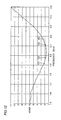
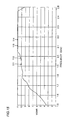
- the relationship between the VSWR and frequency is shown in Fig. 12. It is appreciated from the Smith chart of Fig. 11 that in the antenna element of the present invention, the locus of the impedance is concentrated in the proximity of the center point of the Smith chart and that the reflection coefficient is small. It is particularly appreciated that the reflection coefficient at the regions of points 101-104 is particularly small since points 101-104 are located in the proximity of the center point. Also, it is appreciated from Fig. 12 that the region where the VSWR is below 2 is the region where the frequency is at least 1.95 GHz and not more than 2.12 GHz. The relative bandwidth is 3.4 %.
- relative bandwidth refers to the relative bandwidth for the region where the VSWR is 2 or below.
- the reason why the property of the antenna is evaluated at the region where the VSWR is below 2 may be due to the fact that, when information communication is effected at a certain frequency (bandwidth), the antenna is designed so that the VSWR at that bandwidth is not more than 2.
- Fig. 13 shows a conventional portable telephone.
- the conventional portable telephone differs from the portable telephone of the present invention shown in Fig. 1 in that meander line antenna 21 is absent.
- feeding point 12 is provided on metal substrate 11, and monopole antenna 22c is directly connected to this feeding point 12.
- the dimensions of metal substrate 11, monopole antenna 22c and helical antenna 22a are similar to those of the antenna element from which the data of Table 1 was obtained. Waves from 1.5 GHz to 2.5 GHz in frequency were caused to be incident upon an antenna element 20z of the portable telephone 1z from feeding point 12 to obtain the impedance property (Smith chart and VSWR) of antenna element 20z.
- the Smith chart is shown in Fig. 14.
- the relationship between the VSWR and frequency is shown in Fig. 15.
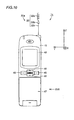
- FIG. 16 is a plan view of a portable telephone to describe the relationship between the portable telephone of the present invention and the axes of X, Y and Z.
- a portable telephone 1a of the present invention was prepared as shown in Fig. 16.
- Portable telephone 1a includes a main unit case 10.
- a protection window 42 is provided at the surface of main unit case 10.
- a liquid crystal panel is disposed behind protection window 42.
- a multifunction switch 46 and an operation key 45 are provided at the center area of main unit case 10.
- a flip 47 is provided at the lower portion of main unit case 10.
- Second antenna unit 22 is provided so as to project from the leading end of main unit case 10.
- Second antenna unit 22 is formed of helical antenna 22a, insulator 22b and monopole antenna 22c.
- Antenna element 20a is provided in main unit case 10.
- Second antenna unit 22 constituting antenna unit 20a is provided projecting from main unit case 10.
- Second antenna unit 22 is formed of helical antenna 22a, insulator 22b and monopole antenna 22c.
- Antenna element 20a is formed likewise antenna element 20a shown in Fig. 1, including metal substrate 11, feeding point 12 and meander line antenna 21 provided in main unit case 10.
- the extending direction of second antenna unit 22 is the +Z direction.
- the direction from right to left in Fig. 16 is the +Y direction.
- the direction at right angles to the paper plane of Fig. 16 towards the rear is the +X direction.
- Fig. 17 is a side view of the portable telephone when viewed from the direction indicated by arrow XVII in Fig. 16.
- a battery 49 is attached to main case 10 of portable telephone 1a.
- Protection window 42 corresponding to a liquid crystal panel display is mounted at the front face of main unit case 10 whereas battery 49 is mounted at the back face of main unit case 10.
- the direction from battery 49 towards second antenna unit 22 is the +Z direction.
- the direction from protection window 42 to the back face of main unit case 10 is the +X direction.
- the direction at right angles to the paper plane of Fig. 17 towards the rear is the +Y direction.
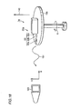
- Figs. 18-20 show the process of measuring the radiation pattern at the X-Z plane.
- portable telephone 1a of Figs. 16 and 17 was placed on a table 150.
- portable telephone 1a was placed so that the extending direction of second antenna unit 22, i.e., the directions of +Z and +X, is substantially orthogonal to the perpendicular direction indicated by arrow 140. Accordingly, the +Y direction is substantially parallel to the perpendicular direction indicated by arrow 140.
- Table 150 is rotatable in a direction indicated by arrow R.
- a wave of 1.95 GHz in frequency was radiated via antenna element 20a in response to a predetermined output from the radio transmitter-receiver.
- table 150 was rotated in the direction indicated by arrow R.
- a wave as shown by arrow 151 was emitted from antenna unit 20a.
- the electric field intensity of this wave was measured using a measurement-oriented antenna 160.
- the electric field intensity of the vertically polarized wave in the direction indicated by arrow V and the horizontally polarized wave in the direction indicated by arrow H was obtained.
- Dipole antenna 170 was placed on table 150.
- Dipole antenna 170 has a feeding point 171 provided at the center portion thereof to which a coaxial cable 172 is connected.
- Coaxial cable 172 is connected to a predetermined radio transmitter-receiver.
- Dipole antenna 170 extends in a direction substantially parallel to the perpendicular direction indicated by arrow 140.
- An output identical to that applied by the radio transmitter-receiver to antenna element 20a of Fig. 18 was supplied to dipole antenna 170 with table 150 rotated in the direction indicated by arrow R.
- a wave of 1.95 GHz in frequency indicated by arrow 152 was radiated from dipole antenna 170.
- a wave indicated by arrow 152 was radiated from dipole antenna 170.
- This wave is a vertically polarized wave in the direction indicated by arrow V.
- the electric field intensity of this wave was measured by measurement-oriented antenna 160.
- dipole antenna 170 was placed on table 150.
- Dipole antenna 170 was disposed so as to extend substantially orthogonal to the perpendicular direction indicated by arrow 140.
- Feeding point 170 is provided at the center of dipole antenna 170.
- Feeding point 171 is connected to a coaxial cable 172.
- An output identical to that applied to antenna element 20a of Fig. 18 by a radio transmitter-receiver was applied to dipole antenna 170 with table 150 rotated in the direction indicated by arrow R, whereby a wave of 1.95 GHz in frequency indicated by arrow 153 was radiated from dipole antenna 170.
- This wave is a horizontally polarized wave in the direction indicated by arrow H.
- the electric field intensity of this wave was obtained by measurement-oriented antenna 160.
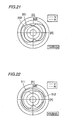
- the radiation pattern of the antenna element of the present invention was obtained based on the data obtained by the processes shown in Figs. 18-20. The result is shown in Fig. 21.
- the solid line 301 indicates the gain of the vertical polarization component of the wave radiated from antenna element 20a of Fig. 18 with respect to the electric field intensity of the vertically polarized wave emitted from dipole antenna 170 in the process shown in Fig. 19.
- the dotted line 302 indicates the gain of the horizontal polarization of the wave emitted from antenna element 20a of Fig. 18 with respect to the electric field intensity of a horizontally polarized wave emitted from dipole antenna 170 in the process shown in Fig. 20.
- Fig. 21 it is appreciated from Fig. 21 that the gain of vertical polarization is greater than the gain of horizontal polarization in antenna element 20a of the present invention.
- one scale mark indicates 10 dB.
- the point on the X axis which is the horizontal axis in Fig. 21 corresponds to the point of the gain under the state where the X axis shown in Figs. 16 and 17 is towards the direction of measurement-oriented antenna 160.
- the point on the Z axis which is the vertical axis in Fig. 21 is the point indicating the gain under the state where the Z axis shown in Figs. 16 and 17 is towards the direction of measurement-oriented antenna 160.
- the average gain was -4.56 dBd.
- the peak value of gain was -0.86 dBd.
- portable telephone 1a was placed on table 150 so that the Z axis (the extending direction of second antenna unit 22) is at an angle of approximately 60° with the perpendicular direction indicated by arrow 140.
- a predetermined output was applied to antenna element 20a from a radio transmitter-receiver while table 150 shown in Fig. 18 is rotated in the direction of arrow R, whereby a wave was radiated.
- the angle between the extending direction of the antenna and the perpendicular direction is generally approximately 60°.
- the radiation pattern corresponding to the state where the Z axis is arranged 60° tilted from the perpendicular direction is shown in Fig. 22.
- the solid line 311 indicates the gain of the intensity of the vertical polarization component of the wave emitted from antenna element 20a having the Z axis tilted 60° to the perpendicular direction with respect to the electrical field intensity of the vertically polarized wave measured by the process of Fig. 19.
- the dotted line 312 indicates the gain of the electric field intensity of the horizontal polarization component of the wave radiated from antenna 20a having the Z axis tilted 60° to the perpendicular direction with respect to the intensity of the horizontally polarized wave measured in the process of Fig. 20.
- Fig. 22 It is appreciated from Fig. 22 that the gain of the vertically and horizontally polarized waves when the Z axis of the antenna element is tilted 60° with respect to the perpendicular direction, i.e. when in a normal conversation state of the portable telephone, is increased.
- the average gain was -4.27 dBd, which is a favorable value.
- the peak value of gain was -2.82 dBd.
- Portable telephone 1z with the conventional antenna element 20z shown in Fig. 13 was placed on table 150 under a state where the Z axis and X axis are in the horizontal direction and the Y axis is parallel to the perpendicular direction, according to a process similar to that shown in Fig. 18.
- a wave of 1.95 GHz in frequency was radiated via antenna 20z with table 150 rotated in the direction indicated by arrow R.
- an output identical to the output applied by the radio transmitter-receiver to antenna element 20a was applied to antenna element 20z.
- the vertical polarization component and horizontal polarization component of the radiated wave were measured using measurement-oriented antenna 160.
- the radiation pattern for such a conventional antenna is shown in Fig. 23. In Fig.
- the dotted line 322 indicates the gain of the electric field intensity of the horizontal polarization component of the wave radiated from antenna element 20z according to the process of Fig. 18 with respect to the electric field intensity of the horizontally polarized wave measured in the process of Fig. 20.
- Fig. 23 It is appreciated from Fig. 23 that the gain of both the horizontal polarization component and vertical polarization component is reduced.
- the average gain obtained from Fig. 23 was -4.74 dBd.
- the peak value of gain was -1.13 dBd.
- Portable telephone 1z was placed on table 150 so that the Z axis (the extending direction of helical antenna 22a and monopole antenna 22c) of portable telephone 1z on table 150 is at an angle of approximately 60° with the perpendicular direction indicated by arrow 140.
- a wave of 1.95 GHz in frequency was radiated from antenna element 20z by a predetermined output with table 150 rotated in the direction indicated by arrow R.
- the electric field intensity of the vertical polarization component and horizontal polarization component of this wave was measured using measurement-oriented antenna 160.
- the radiation pattern of an antenna element arranged so that the Z axis is angled 60° with the perpendicular direction is shown in Fig. 24.
- the solid line 331 indicates the gain of the electric field intensity of the wave emitted from antenna element 20z that has the Z axis tilted 60° to the perpendicular direction with respect to the electric field intensity of a vertically polarized wave measured by the process shown in Fig. 19.
- the dotted line 332 indicates the gain of the electric field intensity of the horizontal polarization component of the wave radiated from antenna element 20z having the Z axis tilted 60° to the perpendicular direction with respect to the electric field intensity of the horizontally polarized wave measured according to the process of Fig. 20.
- Fig. 24 It is appreciated from Fig. 24 that the gain of both vertically polarized wave and horizontally polarized wave of the conventional product is smaller than that of the product of the present invention.
- the average gain obtained from Fig. 24 was -5.64 dBd.
- the peak value of gain was -3.04 dBd.
- the gain in conversation can be improved as to the transmission/reception of both the components of a horizontally polarized wave and vertically polarized wave in addition to reducing a loss caused by the matching circuit.
- the antenna element of the present invention is applicable to the field of portable information terminals such as portable telephones, and personal computers having communication capability, general radios, particular radios and the like.
Landscapes
- Engineering & Computer Science (AREA)
- Computer Networks & Wireless Communication (AREA)
- Support Of Aerials (AREA)
Abstract
Description
| Point | Frequency (GHz) | Impedance of Antenna Element (Ω) | VSWR | |
| Real Part (Ω) | Imaginary Part (Ω) | |||
| 101 | 1.92 | 40.7 | -35.4 | 2.2 |
| 102 | 1.98 | 37.2 | -22.1 | 1.8 |
| 103 | 2.11 | 35.3 | 22.9 | 1.9 |
| 104 | 2.17 | 33.9 | 35.8 | 2.5 |
| Point | Frequency (GHz) | Impedance of Antenna Element (Ω) | VSWR | |
| Real Part (Ω) | Imaginary Part (Ω) | |||
| 111 | 1.92 | 51.0 | -136.5 | 9.2 |
| 112 | 1.98 | 35.0 | -113.2 | 9.3 |
| 113 | 2.11 | 29.1 | -112.7 | 11.2 |
| 114 | 2.17 | 21.7 | -109.8 | 13.8 |
Claims (9)
- An antenna element comprising:a first antenna unit (21, 23, 24, 25, 26) formed so as to extend in one direction; anda second antenna unit (22) extending substantially orthogonal to the extending direction of said first antenna unit (21, 23, 24, 25, 26), having an electrical length of substantially (λ/2) × A (A is an integer), and coupled to said first antenna unit (21, 23, 24, 25, 26).
- The antenna element according to claim 1, wherein said first antenna unit (21, 23, 24, 25, 26) has an electrical length of approximately (λ/4) + (λ/2) × B (B is an integer).
- The antenna element according to claim 1, wherein said first antenna unit (21, 23, 24, 25, 26) includes at least one type of antenna selected from the group consisting of a plate antenna (25, 26b), a monopole antenna, a helical antenna (23), a meander line antenna (21, 26a) and a zigzag antenna (24).
- The antenna element according to claim 1, wherein said second antenna unit (22) includes a line antenna (22a, 22c).
- The antenna element according to claim 4, wherein said line antenna (22a, 22c) includes at least one type of antenna selected from the group consisting of a monopole antenna (22c) and a helical antenna (22a).
- The antenna element according to claim 1, further comprising a substrate (11) with a conductive surface,
said first antenna unit (21, 23, 24, 25, 26) being provided on the surface of said substrate (11) with a dielectric (31) therebetween, and
said second antenna unit (22) being provided so as to extend from said substrate (11). - The antenna element according to claim 1, wherein said first antenna unit (21, 23, 24, 25, 26) and said second antenna unit (22) are attached in order to a feeding point (12).
- A portable information terminal comprising:a main unit case (10); andan antenna element (20a-20h) including a first antenna unit (21, 23, 24, 25, 26) arranged within said main unit case (10), and formed to extend in one direction, and a second antenna unit (22) extending substantially orthogonal to the extending direction of said first antenna unit (21, 23, 24, 25, 26), and arranged projectable from said main unit case (10), having an electrical length of approximately (λ/2) × A (A is an integer), and coupled to said first antenna unit (21, 23, 24, 25, 26).
- The portable information terminal according to claim 8, wherein said second antenna unit (22) comprises a third antenna unit (22a) having an electrical length of approximately (λ/2) × C (C is an integer), and a fourth antenna unit (22c) coupled to said third antenna unit (22a), and having an electrical length of approximately (λ/2) × D (D is an integer),
said third and said fourth antenna units (22a, 22c) projecting from said main unit case (10) when said antenna element (20a-20h) is pulled out from said main unit case (10), and
said third antenna unit (20a) projecting from said main unit case (10) and said fourth antenna unit (20c) located in said main unit case (10) when said antenna element (20a-20h) is stored in said main unit case (10).
Applications Claiming Priority (1)
| Application Number | Priority Date | Filing Date | Title |
|---|---|---|---|
| PCT/JP2000/003528 WO2001093368A1 (en) | 2000-06-01 | 2000-06-01 | Antenna element and portable information terminal |
Publications (2)
| Publication Number | Publication Date |
|---|---|
| EP1289051A1 true EP1289051A1 (en) | 2003-03-05 |
| EP1289051A4 EP1289051A4 (en) | 2005-01-26 |
Family
ID=11736101
Family Applications (1)
| Application Number | Title | Priority Date | Filing Date |
|---|---|---|---|
| EP00935513A Withdrawn EP1289051A4 (en) | 2000-06-01 | 2000-06-01 | ANTENNA ELEMENT AND PORTABLE INFORMATION TERMINAL |
Country Status (4)
| Country | Link |
|---|---|
| US (1) | US6768464B1 (en) |
| EP (1) | EP1289051A4 (en) |
| CN (1) | CN1367943A (en) |
| WO (1) | WO2001093368A1 (en) |
Cited By (1)
| Publication number | Priority date | Publication date | Assignee | Title |
|---|---|---|---|---|
| EP1753083A1 (en) * | 2005-08-10 | 2007-02-14 | Wistron NeWeb Corp. | Monopole antennas |
Families Citing this family (12)
| Publication number | Priority date | Publication date | Assignee | Title |
|---|---|---|---|---|
| KR100998409B1 (en) * | 2002-07-31 | 2010-12-03 | 파나소닉 주식회사 | Handheld wireless communication device |
| KR100450878B1 (en) * | 2003-06-13 | 2004-10-13 | 주식회사 에이스테크놀로지 | Built-in antenna with a center feed structure for wireless terminal |
| US7383063B2 (en) * | 2003-09-18 | 2008-06-03 | Kyocera Wireless Corp. | Communication device with diversity antenna |
| JP2006121444A (en) * | 2004-10-21 | 2006-05-11 | Nec Access Technica Ltd | Automatic regulation circuit, automatic regulation method and portable terminal |
| KR20060038135A (en) * | 2004-10-29 | 2006-05-03 | 삼성전자주식회사 | Internal antenna of the mobile terminal |
| KR101281735B1 (en) * | 2006-08-03 | 2013-07-04 | 삼성전자주식회사 | Extendable built-in antenna unit of mobile device |
| KR101394268B1 (en) * | 2007-09-27 | 2014-05-26 | 삼성전자주식회사 | Mobile terminal having additional antenna pattern in a main body |
| KR20110123089A (en) * | 2010-05-06 | 2011-11-14 | 삼성전자주식회사 | Antenna device of mobile terminal |
| MY160952A (en) * | 2012-02-15 | 2017-03-31 | Motorola Solutions Inc | Hybrid antenna for portable communication devices |
| GB201404209D0 (en) * | 2014-03-10 | 2014-04-23 | E2V Tech Uk Ltd | Method and apparatus for remotely disabling vehicles |
| US9363794B1 (en) | 2014-12-15 | 2016-06-07 | Motorola Solutions, Inc. | Hybrid antenna for portable radio communication devices |
| CN109155454B (en) * | 2016-05-16 | 2020-10-02 | 摩托罗拉解决方案公司 | Dual contrawound antenna for communication equipment |
Family Cites Families (23)
| Publication number | Priority date | Publication date | Assignee | Title |
|---|---|---|---|---|
| JPH0631949Y2 (en) * | 1989-05-30 | 1994-08-24 | 有限会社システム・キャブ | Desk for OA equipment |
| GB2257838B (en) * | 1991-07-13 | 1995-06-14 | Technophone Ltd | Retractable antenna |
| US5262792A (en) * | 1991-09-11 | 1993-11-16 | Harada Kogyo Kabushiki Kaisha | Shortened non-grounded type ultrashort-wave antenna |
| JP2502426B2 (en) * | 1991-11-08 | 1996-05-29 | 原田工業株式会社 | Broadband ultra high frequency antenna |
| JP2531394B2 (en) | 1992-01-23 | 1996-09-04 | 村田機械株式会社 | Mobile phone |
| JP3259411B2 (en) | 1992-09-21 | 2002-02-25 | 松下電器産業株式会社 | Mobile radio antenna |
| JPH0738316A (en) | 1993-07-26 | 1995-02-07 | Harada Ind Co Ltd | Telescopic antenna for mobile phones |
| JP3305487B2 (en) | 1994-03-31 | 2002-07-22 | 株式会社エヌ・ティ・ティ・ドコモ | Communication equipment |
| JP3059336B2 (en) | 1994-04-06 | 2000-07-04 | 三菱電機株式会社 | Antenna device and mobile communication device |
| JP3510391B2 (en) | 1995-06-27 | 2004-03-29 | Smk株式会社 | Antenna device |
| US5892483A (en) * | 1996-03-15 | 1999-04-06 | Ericsson Inc. | Dual antenna arrangement for portable transceiver |
| EP1345283A1 (en) * | 1996-06-20 | 2003-09-17 | Kabushiki Kaisha Yokowo (also trading as Yokowo Co., Ltd.) | Antenna |
| JPH1048535A (en) | 1996-08-05 | 1998-02-20 | Terumo Corp | Stereo-adaptor for endoscope and controller used together with adaptor |
| JP3126313B2 (en) * | 1996-09-19 | 2001-01-22 | 松下電器産業株式会社 | Antenna device |
| JPH10173422A (en) | 1996-12-13 | 1998-06-26 | Casio Comput Co Ltd | Wireless communication device |
| JP3048535B2 (en) | 1997-04-10 | 2000-06-05 | 日本道路公団 | Legal block |
| SE511501C2 (en) * | 1997-07-09 | 1999-10-11 | Allgon Ab | Compact antenna device |
| JPH11205037A (en) | 1998-01-20 | 1999-07-30 | Kokusai Electric Co Ltd | Diversity antenna for mobile phones |
| KR100263181B1 (en) * | 1998-02-27 | 2000-08-01 | 윤종용 | Antenna of portable radio equipment |
| JP3467752B2 (en) | 1998-03-18 | 2003-11-17 | Necトーキン株式会社 | Mobile communication terminal and its antenna device |
| US6326924B1 (en) * | 1998-05-19 | 2001-12-04 | Kokusai Electric Co., Ltd. | Polarization diversity antenna system for cellular telephone |
| US6211830B1 (en) * | 1998-06-10 | 2001-04-03 | Matsushita Electric Industrial Co., Ltd. | Radio antenna device |
| JP2000036702A (en) * | 1998-07-21 | 2000-02-02 | Hitachi Ltd | Wireless terminal |
-
2000
- 2000-06-01 US US10/030,113 patent/US6768464B1/en not_active Expired - Fee Related
- 2000-06-01 WO PCT/JP2000/003528 patent/WO2001093368A1/en not_active Ceased
- 2000-06-01 CN CN00811135A patent/CN1367943A/en active Pending
- 2000-06-01 EP EP00935513A patent/EP1289051A4/en not_active Withdrawn
Cited By (1)
| Publication number | Priority date | Publication date | Assignee | Title |
|---|---|---|---|---|
| EP1753083A1 (en) * | 2005-08-10 | 2007-02-14 | Wistron NeWeb Corp. | Monopole antennas |
Also Published As
| Publication number | Publication date |
|---|---|
| US6768464B1 (en) | 2004-07-27 |
| EP1289051A4 (en) | 2005-01-26 |
| WO2001093368A1 (en) | 2001-12-06 |
| CN1367943A (en) | 2002-09-04 |
Similar Documents
| Publication | Publication Date | Title |
|---|---|---|
| US6215447B1 (en) | Antenna assembly for communications devices | |
| US6424300B1 (en) | Notch antennas and wireless communicators incorporating same | |
| US6664932B2 (en) | Multifunction antenna for wireless and telematic applications | |
| US5539414A (en) | Folded dipole microstrip antenna | |
| US6326927B1 (en) | Capacitively-tuned broadband antenna structure | |
| US6268831B1 (en) | Inverted-f antennas with multiple planar radiating elements and wireless communicators incorporating same | |
| US6801164B2 (en) | Broad band and multi-band antennas | |
| US6229487B1 (en) | Inverted-F antennas having non-linear conductive elements and wireless communicators incorporating the same | |
| KR100849810B1 (en) | Antenna apparatus | |
| JPH10163731A (en) | Common antenna and portable radio using the same | |
| JPH11317616A (en) | Directional antenna for mobile telephone | |
| US6768464B1 (en) | Antenna element and portable information terminal | |
| US5945950A (en) | Stacked microstrip antenna for wireless communication | |
| US7148848B2 (en) | Dual band, bent monopole antenna | |
| US20020033772A1 (en) | Broadband antenna assembly of matching circuitry and ground plane conductive radiating element | |
| JP2001244715A (en) | Antenna device | |
| JPH05243837A (en) | Slot antenna | |
| EP1289050A1 (en) | Portable wireless terminal | |
| JPH0998018A (en) | Shared antenna | |
| JP2001024426A (en) | Antenna element and circularly polarized antenna system using the same | |
| KR100531624B1 (en) | Ultra WideBand Inverted L Antenna Apparatus | |
| JP3481801B2 (en) | Planar antenna and portable radio using the same | |
| JP3237604B2 (en) | Antenna device | |
| GB2284936A (en) | Folded dipole microstrip antenna | |
| JPWO2001093368A1 (en) | Antenna element and mobile information terminal |
Legal Events
| Date | Code | Title | Description |
|---|---|---|---|
| PUAI | Public reference made under article 153(3) epc to a published international application that has entered the european phase |
Free format text: ORIGINAL CODE: 0009012 |
|
| 17P | Request for examination filed |
Effective date: 20020225 |
|
| AK | Designated contracting states |
Kind code of ref document: A1 Designated state(s): AT BE CH CY DE DK ES FI FR GB GR IE IT LI LU MC NL PT SE Designated state(s): AT BE CH CY DE DK ES FI FR GB GR IE IT LI LU MC NL PT SE |
|
| AX | Request for extension of the european patent |
Extension state: AL LT LV MK RO SI |
|
| RBV | Designated contracting states (corrected) |
Designated state(s): DE FR GB |
|
| A4 | Supplementary search report drawn up and despatched |
Effective date: 20041213 |
|
| RIC1 | Information provided on ipc code assigned before grant |
Ipc: 7H 01Q 9/30 B Ipc: 7H 01Q 1/38 B Ipc: 7H 01Q 1/36 B Ipc: 7H 01Q 1/24 A |
|
| STAA | Information on the status of an ep patent application or granted ep patent |
Free format text: STATUS: THE APPLICATION HAS BEEN WITHDRAWN |
|
| 18W | Application withdrawn |
Effective date: 20050324 |