EP1289050A1 - Portable wireless terminal - Google Patents
Portable wireless terminal Download PDFInfo
- Publication number
- EP1289050A1 EP1289050A1 EP00935512A EP00935512A EP1289050A1 EP 1289050 A1 EP1289050 A1 EP 1289050A1 EP 00935512 A EP00935512 A EP 00935512A EP 00935512 A EP00935512 A EP 00935512A EP 1289050 A1 EP1289050 A1 EP 1289050A1
- Authority
- EP
- European Patent Office
- Prior art keywords
- substrate
- portable telephone
- feed unit
- antenna
- metal substrate
- Prior art date
- Legal status (The legal status is an assumption and is not a legal conclusion. Google has not performed a legal analysis and makes no representation as to the accuracy of the status listed.)
- Withdrawn
Links
Images






Classifications
-
- H—ELECTRICITY
- H01—ELECTRIC ELEMENTS
- H01Q—ANTENNAS, i.e. RADIO AERIALS
- H01Q1/00—Details of, or arrangements associated with, antennas
- H01Q1/52—Means for reducing coupling between antennas; Means for reducing coupling between an antenna and another structure
- H01Q1/526—Electromagnetic shields
-
- H—ELECTRICITY
- H01—ELECTRIC ELEMENTS
- H01Q—ANTENNAS, i.e. RADIO AERIALS
- H01Q1/00—Details of, or arrangements associated with, antennas
- H01Q1/12—Supports; Mounting means
- H01Q1/22—Supports; Mounting means by structural association with other equipment or articles
- H01Q1/24—Supports; Mounting means by structural association with other equipment or articles with receiving set
- H01Q1/241—Supports; Mounting means by structural association with other equipment or articles with receiving set used in mobile communications, e.g. GSM
- H01Q1/242—Supports; Mounting means by structural association with other equipment or articles with receiving set used in mobile communications, e.g. GSM specially adapted for hand-held use
-
- H—ELECTRICITY
- H01—ELECTRIC ELEMENTS
- H01Q—ANTENNAS, i.e. RADIO AERIALS
- H01Q9/00—Electrically-short antennas having dimensions not more than twice the operating wavelength and consisting of conductive active radiating elements
- H01Q9/04—Resonant antennas
- H01Q9/16—Resonant antennas with feed intermediate between the extremities of the antenna, e.g. centre-fed dipole
-
- H—ELECTRICITY
- H01—ELECTRIC ELEMENTS
- H01Q—ANTENNAS, i.e. RADIO AERIALS
- H01Q9/00—Electrically-short antennas having dimensions not more than twice the operating wavelength and consisting of conductive active radiating elements
- H01Q9/04—Resonant antennas
- H01Q9/30—Resonant antennas with feed to end of elongated active element, e.g. unipole
- H01Q9/32—Vertical arrangement of element
Definitions
- the present invention relates to portable radio terminals, particularly to a portable telephone as the portable radio terminal.
- a portable telephone generally includes an antenna element to transmit and receive electromagnetic waves, and a radio transmitter-receiver provided in the portable telephone to apply energy to the antenna element. Since the impedance of the antenna element differs from the impedance of the radio transmitter-receiver, the impedance must be matched. Therefore, a matching circuit is provided between the radio transmitter-receiver and the antenna element in a conventional portable telephone for impedance matching.
- Fig. 15 shows a structure of a conventional portable telephone.
- a conventional portable telephone 401 includes a main unit case 410, a metal substrate 411, a feed unit 412, a matching circuit 413, a shield box 414, and a monopole antenna 421.
- Metal substrate 411 is housed in main unit case 410.
- Shield box 414 is disposed at the surface of metal substrate 411, and matching circuit 413 constituting feed unit 412 is provided in the proximity of shield box 414.
- Monopole antenna 421 is connected to matching circuit 413.
- Main unit case 410 is of a hollow configuration with metal substrate 411 located therein.
- Metal substrate 411 includes an epoxy glass material and a conductor layer 441a formed of copper at the surface thereof.
- Metal substrate 411 is of a rectangular configuration and has long sides and short sides.
- Shield box 414 is provided at the upper portion of metal substrate 411.
- a radio transmitter-receiver is provided in shield box 414 to extract the information included in the wave received by monopole antenna 421 and to apply a predetermined energy to monopole antenna 421 to radiate waves.
- the radio transmitter-receiver is covered with shield box 414 to be shielded electromagnetically.
- Shield box 414 is configured, for example, by a layered body of copper and nickel with a nickel layer formed at the surface of copper.
- Matching circuit 413 configuring feed unit 412 is provided so as to face a portion of shield box 414.
- Matching circuit 413 is formed of a lumped constant element such as coils and capacitors.
- Matching circuit 413 has a portion connected to the radio transmitter-receiver in shield box 414. The remaining portion of matching circuit 413 is connected to monopole antenna 421.
- Monopole antenna 421 is attached to matching circuit 413 so as to extend in a predetermined direction.
- Monopole antenna 421 extends along the longitudinal direction of metal substrate 411 and main unit case 410.
- the electrical length of monopole antenna 421 is mainly set to ⁇ /4 or ⁇ /2.
- monopole antenna 421 receives a wave
- a current flow is conducted from feed unit 412 to the radio transmitter-receiver in shield box 414.
- a current that flows at the surface of shield box 414 as shown by arrow 430 is also present.
- An object of the present invention is to provide a portable radio terminal that has a high antenna efficiency and improved in gain.
- a portable radio terminal includes a substrate, a shield member, an antenna element, and a feed unit.
- the substrate includes a portion having a conductive surface.
- the shield member covers a radio transmitter-receiver provided on the substrate to shield the radio transmitter-receiver electromagnetically, and has conductivity.
- the antenna element has an electrical length of ( ⁇ /2) ⁇ N (N is an integer), and extends in a predetermined direction.
- the feed unit is provided at the substrate so as to be apart from the shield member in an extending direction of the antenna element, and includes a matching circuit connected to the antenna element.
- the feed unit is provided at the substrate so as to be apart from the shield member in the extending direction of the antenna element. Since the feed unit is apart from the shield member in the extending direction of the antenna element, the current flowing to the shield member can be reduced to prevent occurrence of a loss in electric signals. Thus, a portable radio terminal of high antenna efficiency and improved in gain can be provided.
- the end portion of the substrate is dielectric at the surface.
- the feed unit is provided at the portion of the substrate that is dielectric. Since there is no conductive portion where the feed unit is located, the current flowing to the conductive portion can be reduced. As a result, a loss in the electric signal can be prevented. Thus, a portable radio terminal of high antenna efficiency and improved in gain can be provided.
- the end portion of the substrate has a protruding portion where the feed unit is provided. Since the feed unit provided at the protruding portion is immune to the effect of the shield member, a loss in electrical signals can further be prevented effectively.
- the shield member, feed unit and antenna element are provided sequentially so as to be distant from the substrate along the extending direction of the antenna element. Since the feed unit is provided apart from the substrate, the current flowing to the conductive portion can be reduced. As a result, a loss in the electric signal can be prevented. Thus, a portable radio terminal of high antenna efficiency and improved in gain can be provided.
- a portable radio terminal includes a substrate, a shield member, a dielectric, a feed unit, and an antenna element.
- the surface of the substrate is conductive.
- the shield member covers a radio transmitter-receiver provided on the substrate to shield the radio transmitter-receiver electromagnetically, and has conductivity.
- the dielectric is provided on the substrate.
- the feed unit is provided on the dielectric so as to be apart from the surface of the substrate in the thickness direction of the substrate, and includes a matching circuit.
- the antenna element has an electrical length of ( ⁇ /2) ⁇ N (N is an integer), and is connected to the feed unit.
- the feed unit is provided on the dielectric so as to be apart in the thickness direction of the substrate's surface. Since the feed unit is provided apart in the direction perpendicular to the surface of the substrate, the current flowing from the feed unit to the shield member or to the surface of the substrate can be reduced. As a result, a loss in electric signals can be prevented. Thus, a portable radio terminal of high antenna efficiency and improved in gain can be provided.
- Fig. 1 is a plan view of a portable telephone according to a first embodiment of the present invention.
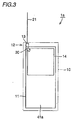
- a portable telephone 1a as the portable radio terminal of the first embodiment of the present invention includes a metal substrate 11 as the substrate, a shield box 14 as the shield member, a monopole antenna 21 as the antenna element, and a feed unit 12.
- a metal layer 41a having conductivity is formed at the surface of metal substrate 11.
- Shield box 14 covers the radio transmitter-receiver provided on metal substrate 11 to shield the radio transmitter-receiver electromagnetically, and has conductivity.
- the electrical length of monopole antenna 21 is ( ⁇ /2) ⁇ N (N is an integer).
- Monopole antenna 21 is formed to extend in a predetermined direction.
- Feed unit 12 has a matching circuit 13 connected to monopole antenna 21.
- Feed unit 12 is provided on metal substrate 11 apart from shield box 14 in the extending direction of monopole antenna 21.
- Metal substrate 11, feed unit 12, matching circuit 13 and shield box 14 are accommodated in main unit case 10.
- Metal substrate 11 includes an insulator formed of an epoxy glass material, and a metal layer 41a formed of copper on the insulator.
- a metal shield box 14 of substantially a cuboid configuration At the surface of metal layer 41a is provided a metal shield box 14 of substantially a cuboid configuration.
- Shield box 14 is constituted by, for example, a layered body having a nickel layer formed at the surface of copper.
- a radio transmitter-receiver is provided in the space enclosed by shield box 14. This radio transmitter-receiver is connected to matching circuit 13 through a microstrip line or coaxial cable.
- Monopole antenna 21 can be replaced with another antenna element such as a helical element.
- a monopole antenna and a helical antenna can be coupled through ABS (alkyl benzene sulfonic acid) resin or the like to be attached to matching circuit 13.
- Fig. 2 is a side view of the portable telephone according to the first embodiment of the present invention shown in Fig. 1 in a used state.
- portable telephone 1a includes main unit 10, matching circuit 13 and monopole antenna 21.
- Main unit case 10 is formed to extend in one direction, and has a speaker 15 that is to be located close to one's ear and a microphone 16 that is to be located close to one's mouth, provided at the surface. The surface where speaker 15 and microphone 16 are provided is formed so as to fit along one's head 20.
- Matching circuit 13 is disposed in main unit case 10.
- Main unit case 10 extends so as to be distant from one's head 20 as a function of approach to monopole antenna 21.
- Matching circuit 13 is provided at the end portion of main unit case 10.
- the face side where microphone 16 and speaker 15 are provided is the front surface and the opposite side thereof is the back surface.
- Matching circuit 13 is provided in the proximity of the back surface, apart from one's head 20.
- Fig. 3 is a plan view of the portable telephone according to the first embodiment of the present invention to describe the operation thereof.
- portable telephone 1a of the present invention has feed unit 12 with matching circuit 13 provided apart from the shield box and metal substrate 11 in the extending direction of monopole antenna 21. Therefore, the current is conducted to the radio transmitter-receiver in shield box 14 from feed unit 12 as indicated by arrow 30. Accordingly, the current flowing to the surface of shield box 14 can be reduced. Also, the current flowing to the surface of metal substrate 11 can be reduced. As a result, the loss can be prevented.
- a portable telephone improved in antenna efficiency and of high gain can be provided.
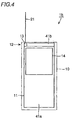
- Fig. 4 is a plan view of a portable telephone according to a second embodiment of the present invention.
- a portable telephone 1b of the second embodiment differs from portable telephone 1a of Fig. 1 in that metal layer 41a at the end of metal substrate 11 is absent and that a dielectric layer 41b with the epoxy glass material exposed is provided.
- Feed unit 12 with matching circuit 13 is provided on a dielectric layer 41b.
- Monopole antenna 21 is connected to matching circuit 13.
- Portable telephone 1b of the above structure provides advantageous effects similar to those of portable telephone 1a of the first embodiment. Furthermore, feed unit 12 is formed on dielectric layer 41b that is not conductive. Therefore, the current flowing to the surface of metal layer 41a at the surface of metal substrate 11 can be reduced. As a result, a portable telephone that has reduction in the antenna efficiency prevented and of high gain can be provided.
- Portable telephone 1b of the second embodiment is advantageous in that dielectric layer 41b can be fabricated by a simple process since dielectric layer 41b can be exposed by just removing metal layer 41a at the leading end of metal substrate 11.
- Fig. 5 is a plan view of a portable telephone according to a third embodiment of the present invention.
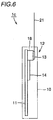
- Fig. 6 is a side view of the portable telephone of the third embodiment viewed from the direction indicated by arrow VI in Fig. 5.
- a portable telephone 1c of the third embodiment differs from portable telephone 1a of Fig. 1 in that matching circuit 13 is provided at the surface of metal substrate 11 with a dielectric block 18 therebetween.
- Dielectric block 18 is of a cuboid configuration, and has one face in contact with the surface of metal substrate 11 and the other face in contact with matching circuit 13.
- Dielectric block 18 is formed of a material having a small dielectric dissipation factor (tan ⁇ ) and a high relative dielectric constant, for example, a ceramics type material (relative dielectric constant ⁇ 7-100), Teflon (relative dielectric constant ⁇ 2.1) and resin based material such as Vectra (relative dielectric constant ⁇ 3.3).
- a ceramics type material for example, a ceramics type material (relative dielectric constant ⁇ 7-100), Teflon (relative dielectric constant ⁇ 2.1) and resin based material such as Vectra (relative dielectric constant ⁇ 3.3).
- the presence of dielectric block 18 allows feed unit 12 with matching circuit 13 to be provided on dielectric block 18 so as to be apart in the thickness direction of metal substrate 11. In other words, matching circuit 13 is provided apart from the surface of metal substrate 11 in the perpendicular direction.
- Dielectric block 18 is enclosed by shield box 14.
- the height of the top face of shield box 14 from the surface of metal substrate 11 is lower than the height of the top face of matching circuit 13 from the surface of metal substrate 11. Therefore, shield box 14 is located at a relatively low position whereas matching circuit 13 is located at a relatively high position.
- Monopole antenna 21 may be replaced with a line antenna such as a helical antenna.
- Portable telephone 1c of the third embodiment configured as described above is characterized in that feed unit 12 with matching circuit 13 is provided on dielectric block 18 so as to be apart in the thickness direction of metal substrate 11. Therefore, the current flowing from matching circuit 13 to the surface of shield box 14 directly or to the surface of metal substrate 11 can be reduced. Since there is no occurrence of a loss in current, a portable telephone improved in antenna efficiency and of high gain can be provided. Furthermore, since matching circuit 13 is formed on dielectric block 18, the wavelength of the wave flowing through matching circuit 13 is reduced. As a result, there is an advantageous effect that matching circuit 13 can be reduced in size.
- Fig. 7 is a plan view of a portable telephone according to a fourth embodiment of the present invention.
- a portable telephone 1d according to the fourth embodiment of the present invention differs from portable telephone 1a of Fig. 1 in that a protruding portion 52 is formed at the leading end of metal substrate 11, and feed unit 12 with matching circuit 13 is formed at this protruding portion 52.
- a concave 15 is provided adjacent to protruding portion 52.
- the sizes of concave 53 and protruding portion 52 can be altered appropriately depending upon the size of portable telephone 1d and the size of matching circuit 13.
- Portable telephone 1d of the above configuration provides advantageous effects similar to those of portable telephone 1a of the first embodiment.
- Portable telephone 1a of the present invention as shown in Fig. 1 had the length W 1 of the longer side and the length W 2 of the shorter side of metal substrate 11 set to 0.85 ⁇ and 0.2 ⁇ , respectively.
- the electrical length of monopole antenna 21 was set to ⁇ /2.
- the distance L 1 from metal substrate 11 to the end of monopole antenna 21 was set to 0.05 ⁇ .
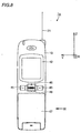
- Such a metal substrate 11 is covered with a main unit case 10 as shown in Fig. 8.
- a protection window 41 is provided at the surface of main unit case 10.
- a liquid crystal panel is provided behind protection window 42.
- a multifunction switch 46 and an operation key 45 are provided at the center area of main unit case 10.
- a flip 47 is provided at the lower portion of main unit case 10.
- Monopole antenna 21 is provided so as to project from main unit case 10.
- the extending direction of monopole antenna 21 is the +Z direction.
- the direction from right to left in Fig. 8 is the +Y direction.
- the direction at right angles to the paper plane of Fig. 8 towards the rear is the +X direction.
- Fig. 9 is a side view of the portable telephone when viewed from the direction indicated by arrow IX in Fig. 8.
- a battery 49 is attached to main case 10 of portable telephone 1a.
- Protection window 42 corresponding to a liquid crystal panel display is mounted at the front face of main unit case 10 whereas battery 49 is mounted at the back face of main unit case 10.
- the direction from battery 49 towards monopole antenna 21 is the +Z direction.
- the direction from protection window 42 to the back face of main unit case 10 is the +X direction.
- the direction at right angles to the paper plane of Fig. 9 towards the rear is the +Y direction.
- Figs. 10-12 show the process of measuring the radiation pattern at the X-Z plane.
- portable telephone 1a of Figs. 8 and 9 was placed on a table 150.
- portable telephone 1a was placed so that the extending direction of monopole antenna 21 (the +Z direction) and the X direction are substantially orthogonal to the perpendicular direction indicated by arrow 140. Accordingly, the +Y direction is substantially parallel to the direction indicated by arrow 140.
- Table 150 is rotatable in the direction indicated by arrow R.
- a wave of 1.95 GHz in frequency was radiated via monopole antenna 21 in response to a predetermined output from the radio transmitter-receiver.
- table 150 was rotated in the direction indicated by arrow R.
- a wave as shown by arrow 151 was emitted from monopole antenna 21.
- the electric field intensity of this wave was measured using a measurement-oriented antenna 160.
- the electric field intensity of the vertically polarized wave in the direction indicated by arrow V and the horizontally polarized wave in the direction indicated by arrow H was obtained.
- a dipole antenna 170 was placed on table 150.
- Dipole antenna 170 has a feeding point 171 provided at the center portion thereof to which a coaxial cable 172 is connected.
- Coaxial cable 172 is connected to a predetermined radio transmitter-receiver.
- Dipole antenna 170 extends in a direction substantially parallel to the perpendicular direction indicated by arrow 140.
- An output identical to that applied by the radio transmitter-receiver to monopole antenna 21 of Fig. 10 was supplied to dipole antenna 170 with table 150 rotated in the direction indicated by arrow R.
- a wave of 1.95 GHz in frequency indicated by arrow 152 was radiated from dipole antenna 170.
- a wave indicated by arrow 152 was radiated from dipole antenna 170.
- This wave is a vertically polarized wave in the direction indicated by arrow V.
- the electric field intensity of this wave was measured by measurement-oriented antenna 160.
- dipole antenna 170 was placed on table 150.
- Dipole antenna 170 was disposed so as to extend substantially orthogonal to the perpendicular direction indicated by arrow 140.
- Feeding point 171 is provided at the center of dipole antenna 170.
- Feeding point 171 is connected to a coaxial cable 172.
- An output identical to that applied to monopole antenna 21 of Fig. 10 by a radio unit was applied to dipole antenna 170 with table 150 rotated in the direction indicated by arrow R, whereby a wave of 1.95 GHz in frequency indicated by arrow 153 was radiated from dipole antenna 170.
- This wave is a horizontally polarized wave in the direction indicated by arrow H.
- the electric field intensity of this wave was obtained by measurement-oriented antenna 160.
- the radiation pattern of the antenna element of the present invention was obtained based on the data obtained by the processes shown in Figs. 10-12. The result is shown in Fig. 13.
- the solid line 301 indicates the gain of the vertical polarization component of the wave radiated from monopole antenna 21 of Fig. 10 with respect to the electric field intensity of the vertically polarized wave emitted from dipole antenna 170 in the process shown in Fig. 11.
- the dotted line 302 indicates the gain of the horizontal polarization of the wave emitted from monopole antenna 21 of Fig. 10 with respect to the electric field intensity of a horizontally polarized wave emitted from dipole antenna 170 in the process shown in Fig. 12.
- Fig. 13 It is appreciated from Fig. 13 that the gain of vertical polarization is greater than the gain of horizontal polarization in portable telephone 1a of the present invention.
- one scale mark indicates 10 dB.
- the point on the X axis which is the horizontal axis in Fig. 13 corresponds to the point of the gain under the state where the X axis shown in Figs. 8 and 9 is towards the direction of measurement-oriented antenna 160.
- the point on the Z axis which is the vertical axis is the point indicating the gain under the state where the Z axis shown in Figs. 8 and 9 is towards the direction of measurement-oriented antenna 160.
- the average gain was -3.00 dBd.
- the peak value of gain was 0.61 dBd.
- conventional portable telephone 401 of Fig. 15 was placed on table 150 so that the Z axis and the X axis are in the horizontal direction and the Y axis is in the perpendicular direction according to a process similar to that of Fig. 10.
- the size of metal substrate 411 shown in Fig. 15 was set similar to that of metal substrate 411.
- a wave of 1.95 GHz in frequency was radiated via monopole antenna 421 with table 150 rotated in the direction indicated by arrow R.
- an output similar to that applied to monopole antenna 421 by the radio transmitter-receiver was applied to monopole antenna 421.
- the vertical polarization component and horizontal polarization component of the radiated wave were measured using measurement-oriented antenna 160.
- Fig. 14 It is appreciated from Fig. 14 that the gain of the horizontally polarized wave and the gain of the vertically polarized wave are both reduced.
- the average gain obtained from Fig. 14 was -4.74 dBd.
- the peak value of the gain was -1.13 dBd.
- the portable radio terminal of the present invention is applicable, not only to a portable telephone, but also to the field of portable information terminals such as a personal computer with communication capability.
Landscapes
- Engineering & Computer Science (AREA)
- Computer Networks & Wireless Communication (AREA)
- Physics & Mathematics (AREA)
- Electromagnetism (AREA)
- Support Of Aerials (AREA)
- Telephone Set Structure (AREA)
- Details Of Aerials (AREA)
Abstract
Description
Claims (5)
- A portable radio terminal comprising:a substrate (11) including a portion (41a) with a conductive surface;a conductive shield member (14) covering a radio transmitter-receiver provided on said substrate (11),electromagnetically shielding said radio transmitter-receiver;an antenna element (21) extending in a predetermined direction, having an electrical length of (λ/2) × N (N is an integer); anda feed unit (12) provided at said substrate (11) so as to be apart from said shield member (14) in an extending direction of said antenna element (21), including a matching circuit (13) connected to said antenna element (21).
- The portable radio terminal according to claim 1, wherein a portion (41b) of a surface of said substrate (11) at an end region is dielectric, and said feed unit (12) is provided at the dielectric portion (41b).
- The portable radio terminal according to claim 1, wherein an end region of said substrate (11) has a protruding portion (52), and said feed unit (12) is provided at the protruding portion (52).
- The portable radio terminal according to claim 1, wherein said shield member (14), said feed unit (12) and said antenna element (21) are provided in order in an extending direction of said antenna element (21) to be apart from said substrate (11).
- A portable radio terminal comprising:a substrate (11) having a conductive surface;a conductive shield member (14) covering a radio transmitter-receiver unit provided on said substrate (11), electromagnetically shielding said radio transmitter-receiver;a dielectric (18) provided on said substrate (11);a feed unit (12) provided on said dielectric (18) so as to be apart from the surface of said substrate (11) in a thickness direction of said substrate (11), and including a matching circuit (13); andan antenna element (21) connected to said feed unit (12), and having an electrical length of λ/2) × N (N is an integer).
Applications Claiming Priority (1)
| Application Number | Priority Date | Filing Date | Title |
|---|---|---|---|
| PCT/JP2000/003527 WO2001093367A1 (en) | 2000-06-01 | 2000-06-01 | Portable wireless terminal |
Publications (2)
| Publication Number | Publication Date |
|---|---|
| EP1289050A1 true EP1289050A1 (en) | 2003-03-05 |
| EP1289050A4 EP1289050A4 (en) | 2004-11-24 |
Family
ID=11736100
Family Applications (1)
| Application Number | Title | Priority Date | Filing Date |
|---|---|---|---|
| EP00935512A Withdrawn EP1289050A4 (en) | 2000-06-01 | 2000-06-01 | WIRELESS PORTABLE TERMINAL |
Country Status (4)
| Country | Link |
|---|---|
| US (1) | US6633262B1 (en) |
| EP (1) | EP1289050A4 (en) |
| CN (1) | CN1367944A (en) |
| WO (1) | WO2001093367A1 (en) |
Cited By (2)
| Publication number | Priority date | Publication date | Assignee | Title |
|---|---|---|---|---|
| FR2872323A1 (en) * | 2004-06-24 | 2005-12-30 | Sagem | PORTABLE DEVICE WITH ANTENNA AND HOLDING A PRINTING MEDIUM |
| IT201900006665A1 (en) * | 2019-05-09 | 2020-11-09 | Bitron Spa | CONNECTOR ASSEMBLY FOR REMOTE METERING DEVICES AND RELATED REMOTE METERING DEVICE. |
Families Citing this family (5)
| Publication number | Priority date | Publication date | Assignee | Title |
|---|---|---|---|---|
| JP3830773B2 (en) * | 2001-05-08 | 2006-10-11 | 三菱電機株式会社 | Mobile phone |
| US7079077B2 (en) * | 2004-02-02 | 2006-07-18 | Southern Methodist University | Methods and apparatus for implementation of an antenna for a wireless communication device |
| US7205944B2 (en) * | 2004-10-29 | 2007-04-17 | Southern Methodist University | Methods and apparatus for implementation of an antenna for a wireless communication device |
| EP3425728B1 (en) * | 2017-07-07 | 2020-04-01 | ProAnt AB | Connector assembly |
| CN116195134A (en) * | 2020-10-07 | 2023-05-30 | 三星电子株式会社 | Antenna device and electronic device including the antenna device |
Family Cites Families (17)
| Publication number | Priority date | Publication date | Assignee | Title |
|---|---|---|---|---|
| JP2531394B2 (en) | 1992-01-23 | 1996-09-04 | 村田機械株式会社 | Mobile phone |
| JP3259411B2 (en) | 1992-09-21 | 2002-02-25 | 松下電器産業株式会社 | Mobile radio antenna |
| US5335366A (en) * | 1993-02-01 | 1994-08-02 | Daniels John J | Radiation shielding apparatus for a radio transmitting device |
| NL9302192A (en) * | 1993-07-09 | 1995-02-01 | Ericsson Business Mobile Netwo | Wireless phone. |
| JPH0738316A (en) | 1993-07-26 | 1995-02-07 | Harada Ind Co Ltd | Telescopic antenna for mobile phones |
| JP3305487B2 (en) | 1994-03-31 | 2002-07-22 | 株式会社エヌ・ティ・ティ・ドコモ | Communication equipment |
| JP3059336B2 (en) | 1994-04-06 | 2000-07-04 | 三菱電機株式会社 | Antenna device and mobile communication device |
| JPH08222927A (en) * | 1995-02-13 | 1996-08-30 | Sansei Denki Kk | Mount method for helical antenna and mount structure |
| JP3510391B2 (en) | 1995-06-27 | 2004-03-29 | Smk株式会社 | Antenna device |
| JP3664792B2 (en) * | 1996-01-26 | 2005-06-29 | 富士通株式会社 | Portable radio |
| JPH1188209A (en) | 1997-09-11 | 1999-03-30 | Mitsubishi Electric Corp | Mobile communication equipment |
| JPH11101835A (en) * | 1997-09-26 | 1999-04-13 | Sharp Corp | RF communication unit and inspection method thereof |
| US6137998A (en) * | 1997-12-19 | 2000-10-24 | Ericsson Inc. | Shielding for radiotelephones with retractable antennas |
| JP3068543B2 (en) * | 1997-12-19 | 2000-07-24 | 静岡日本電気株式会社 | Portable wireless information terminal |
| US6285327B1 (en) * | 1998-04-21 | 2001-09-04 | Qualcomm Incorporated | Parasitic element for a substrate antenna |
| JPH11274843A (en) * | 1998-03-23 | 1999-10-08 | Tdk Corp | Antenna system |
| US5986608A (en) * | 1998-04-02 | 1999-11-16 | Lucent Technologies Inc. | Antenna coupler for portable telephone |
-
2000
- 2000-06-01 CN CN00811149.9A patent/CN1367944A/en active Pending
- 2000-06-01 WO PCT/JP2000/003527 patent/WO2001093367A1/en not_active Ceased
- 2000-06-01 US US10/030,116 patent/US6633262B1/en not_active Expired - Fee Related
- 2000-06-01 EP EP00935512A patent/EP1289050A4/en not_active Withdrawn
Cited By (4)
| Publication number | Priority date | Publication date | Assignee | Title |
|---|---|---|---|---|
| FR2872323A1 (en) * | 2004-06-24 | 2005-12-30 | Sagem | PORTABLE DEVICE WITH ANTENNA AND HOLDING A PRINTING MEDIUM |
| WO2006010832A1 (en) * | 2004-06-24 | 2006-02-02 | Sagem Monetel | Portable device with antenna and printing substrate support |
| IT201900006665A1 (en) * | 2019-05-09 | 2020-11-09 | Bitron Spa | CONNECTOR ASSEMBLY FOR REMOTE METERING DEVICES AND RELATED REMOTE METERING DEVICE. |
| WO2020225741A1 (en) * | 2019-05-09 | 2020-11-12 | Bitron S.P.A | Connector assembly for telemetering devices and related telemetering device |
Also Published As
| Publication number | Publication date |
|---|---|
| EP1289050A4 (en) | 2004-11-24 |
| CN1367944A (en) | 2002-09-04 |
| US6633262B1 (en) | 2003-10-14 |
| WO2001093367A1 (en) | 2001-12-06 |
Similar Documents
| Publication | Publication Date | Title |
|---|---|---|
| US5945954A (en) | Antenna assembly for telecommunication devices | |
| US5657028A (en) | Small double C-patch antenna contained in a standard PC card | |
| US6549167B1 (en) | Patch antenna for generating circular polarization | |
| US6590539B2 (en) | Antenna device in radio communication terminal | |
| US7079077B2 (en) | Methods and apparatus for implementation of an antenna for a wireless communication device | |
| JP2001339226A (en) | Antenna system | |
| JP4105987B2 (en) | Antenna, antenna module, and wireless communication apparatus including the same | |
| US6762724B2 (en) | Build-in antenna for a mobile communication terminal | |
| CN113196565A (en) | Dual-polarized antenna array | |
| JP5302953B2 (en) | Wireless communication device | |
| JP3139975B2 (en) | Antenna device | |
| KR20070112362A (en) | Method and apparatus for implementing antenna for wireless communication device | |
| TWI258891B (en) | Mobile phone antenna | |
| US6768464B1 (en) | Antenna element and portable information terminal | |
| JPH11340726A (en) | Antenna device | |
| US6633262B1 (en) | Portable wireless terminal | |
| JPH05299929A (en) | Antenna | |
| EP0821428A2 (en) | Portable radio communication apparatus | |
| JP2002500836A (en) | Wireless communication device | |
| JPH11195917A (en) | Antenna system | |
| CN115775976A (en) | antenna equipment | |
| JPH10200438A (en) | Portable radio | |
| JP3809999B2 (en) | Small antenna and electronic component using the same | |
| JPWO2001093367A1 (en) | Portable wireless terminal | |
| WO2025153032A1 (en) | Camera decoration assembly and electronic device |
Legal Events
| Date | Code | Title | Description |
|---|---|---|---|
| PUAI | Public reference made under article 153(3) epc to a published international application that has entered the european phase |
Free format text: ORIGINAL CODE: 0009012 |
|
| 17P | Request for examination filed |
Effective date: 20020301 |
|
| AK | Designated contracting states |
Kind code of ref document: A1 Designated state(s): AT BE CH CY DE DK ES FI FR GB GR IE IT LI LU MC NL PT SE Designated state(s): AT BE CH CY DE DK ES FI FR GB GR IE IT LI LU MC NL PT SE |
|
| AX | Request for extension of the european patent |
Extension state: AL LT LV MK RO SI |
|
| RBV | Designated contracting states (corrected) |
Designated state(s): DE FR GB |
|
| A4 | Supplementary search report drawn up and despatched |
Effective date: 20041008 |
|
| RIC1 | Information provided on ipc code assigned before grant |
Ipc: 7H 01Q 1/52 B Ipc: 7H 01Q 1/24 A |
|
| STAA | Information on the status of an ep patent application or granted ep patent |
Free format text: STATUS: THE APPLICATION HAS BEEN WITHDRAWN |
|
| 17Q | First examination report despatched |
Effective date: 20050329 |
|
| 18W | Application withdrawn |
Effective date: 20050407 |