EP1289049A1 - Portable radio device - Google Patents
Portable radio device Download PDFInfo
- Publication number
- EP1289049A1 EP1289049A1 EP00917400A EP00917400A EP1289049A1 EP 1289049 A1 EP1289049 A1 EP 1289049A1 EP 00917400 A EP00917400 A EP 00917400A EP 00917400 A EP00917400 A EP 00917400A EP 1289049 A1 EP1289049 A1 EP 1289049A1
- Authority
- EP
- European Patent Office
- Prior art keywords
- antenna
- power supply
- supply means
- portable radio
- flip
- Prior art date
- Legal status (The legal status is an assumption and is not a legal conclusion. Google has not performed a legal analysis and makes no representation as to the accuracy of the status listed.)
- Withdrawn
Links
Images


Classifications
-
- H—ELECTRICITY
- H01—ELECTRIC ELEMENTS
- H01Q—ANTENNAS, i.e. RADIO AERIALS
- H01Q3/00—Arrangements for changing or varying the orientation or the shape of the directional pattern of the waves radiated from an antenna or antenna system
- H01Q3/24—Arrangements for changing or varying the orientation or the shape of the directional pattern of the waves radiated from an antenna or antenna system varying the orientation by switching energy from one active radiating element to another, e.g. for beam switching
-
- H—ELECTRICITY
- H01—ELECTRIC ELEMENTS
- H01Q—ANTENNAS, i.e. RADIO AERIALS
- H01Q1/00—Details of, or arrangements associated with, antennas
- H01Q1/08—Means for collapsing antennas or parts thereof
-
- H—ELECTRICITY
- H01—ELECTRIC ELEMENTS
- H01Q—ANTENNAS, i.e. RADIO AERIALS
- H01Q1/00—Details of, or arrangements associated with, antennas
- H01Q1/12—Supports; Mounting means
- H01Q1/22—Supports; Mounting means by structural association with other equipment or articles
- H01Q1/24—Supports; Mounting means by structural association with other equipment or articles with receiving set
- H01Q1/241—Supports; Mounting means by structural association with other equipment or articles with receiving set used in mobile communications, e.g. GSM
- H01Q1/242—Supports; Mounting means by structural association with other equipment or articles with receiving set used in mobile communications, e.g. GSM specially adapted for hand-held use
- H01Q1/243—Supports; Mounting means by structural association with other equipment or articles with receiving set used in mobile communications, e.g. GSM specially adapted for hand-held use with built-in antennas
-
- H—ELECTRICITY
- H01—ELECTRIC ELEMENTS
- H01Q—ANTENNAS, i.e. RADIO AERIALS
- H01Q1/00—Details of, or arrangements associated with, antennas
- H01Q1/12—Supports; Mounting means
- H01Q1/22—Supports; Mounting means by structural association with other equipment or articles
- H01Q1/24—Supports; Mounting means by structural association with other equipment or articles with receiving set
- H01Q1/241—Supports; Mounting means by structural association with other equipment or articles with receiving set used in mobile communications, e.g. GSM
- H01Q1/242—Supports; Mounting means by structural association with other equipment or articles with receiving set used in mobile communications, e.g. GSM specially adapted for hand-held use
- H01Q1/243—Supports; Mounting means by structural association with other equipment or articles with receiving set used in mobile communications, e.g. GSM specially adapted for hand-held use with built-in antennas
- H01Q1/244—Supports; Mounting means by structural association with other equipment or articles with receiving set used in mobile communications, e.g. GSM specially adapted for hand-held use with built-in antennas extendable from a housing along a given path
-
- H—ELECTRICITY
- H01—ELECTRIC ELEMENTS
- H01Q—ANTENNAS, i.e. RADIO AERIALS
- H01Q19/00—Combinations of primary active antenna elements and units with secondary devices, e.g. with quasi-optical devices, for giving the antenna a desired directional characteristic
- H01Q19/005—Patch antenna using one or more coplanar parasitic elements
-
- H—ELECTRICITY
- H01—ELECTRIC ELEMENTS
- H01Q—ANTENNAS, i.e. RADIO AERIALS
- H01Q9/00—Electrically-short antennas having dimensions not more than twice the operating wavelength and consisting of conductive active radiating elements
- H01Q9/04—Resonant antennas
- H01Q9/30—Resonant antennas with feed to end of elongated active element, e.g. unipole
Definitions
- the present invention relates to portable radios or mobile radio sets and, more specifically to a portable radio provided with two types of antennae.
- the portable radio disclosed in the aforementioned laid-open application includes a whip antenna capable of being freely pushed in or pulled out from a casing, and a small antenna contained in the casing.
- the whip antenna is pulled out from the casing and connected to a transmission/reception circuit for communication.
- the whip antenna is contained in the casing, and the internal small antenna is connected to the transmission/reception circuit for communication.
- the aforementioned document does not contain details such as the shapes of the internal small antenna and whip antenna. Thus, if these antennae are simply combined, a problem of inefficiency may arise due to antenna coupling.
- the present invention is made to solve the aforementioned problem.
- An object of the present invention is to alleviate the inefficiency problem due to antenna coupling in a portable radio or a mobile radio set provided with two types of antennae.
- a portable radio or a mobile radio set of the present invention includes a casing, a first linear antenna capable of being pulled out from the casing, a second plate-like antenna contained in the casing and connected to a ground substrate, and a power supply or feeding means for exciting at least one of the first and second antennae.
- the present inventor Having intensively studied to alleviate the inefficiency problem due to antenna coupling in a portable radio provided with two types of antennae, the present inventor has found that the combination of the first linear antenna and the second plate-like antenna connected to the ground substrate provides smaller antenna coupling, as shown in Fig. 7. As a result, the inefficiency due to inter-antenna interference can be alleviated.
- the portable radio preferably includes a switching means between the first and second antennae, and the power supply means.
- the above mentioned switching means may connect the first antenna and power supply means when the first antenna is pulled out, and connect the second antenna and power supply means when the first antenna is pushed in.
- the switching means may connect both the first and second antennae to the power supply means when the first antenna is pulled out, and connect the second antenna to the power supply means when the first antenna is pushed in.
- the switching means may connect both the first and second antennae to the power supply means when the first antenna is pulled out, and also connect both the first and second antennae to the power supply means when the first antenna is pushed in.
- the switching means may connect the first antenna to the power supply means when the first antenna is pulled out, and connect both the first and second antennae to the power supply means when the first antenna is pushed in.
- the first antenna preferably includes a monopole antenna having a length which is an integral multiple of a half wavelength.
- the second antenna preferably includes a patch antenna.
- the first antenna may include a helical antenna arranged in series with the monopole antenna.
- the first antenna is inclined toward the side opposite a human body. In this way, the antenna performance becomes less affected by the human body.
- a portable radio of the present invention includes a casing having a flip, a first antenna provided in the flip, a second plate-like antenna contained in the casing and connected to the ground substrate, and a power supply means for exciting at least one of the first and second antennae.
- the above combination of the first and second antennae also provides smaller antenna coupling as in the invention according to the above mentioned one aspect.
- the above mentioned portable radio preferably includes a switching means between the first and second antennae and the power supply means.
- the switching means may connect the first antenna to the power supply means when the flip is opened, and connect the second antenna to the power supply means when the flip is closed.
- the switching means may connect both the first and second antennae to the power supply means when the flip is opened, and connect the second antenna to the power supply means when the flip is closed.
- the switching means may connect both the first and second antennae to the power supply means when the flip is opened, and connect the first and second antennae to the power supply means when the flip is closed.
- the switching means may connect the first antenna to the power supply means when the flip is opened, and connect both the first and second antennae to the power supply means when the flip is closed.
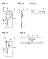
- Figs. 1A to 1D show a portable radio or a mobile radio set 1 such as a portable radio telephone of the first embodiment of the present invention as well as modifications thereof.
- Fig. 1E is a side view of the internal antenna shown in Fig. 1A.
- portable radio 1 includes a casing 2, a first antenna 3, a second antenna 4, a switch 5, and a power supply means 6.
- casing 2 contains a ground substrate 13 on which second antenna 4 is mounted.
- First antenna is preferably a monopole antenna, which can be freely pulled out from and pushed in casing 2.
- a length L1 of first antenna 3 is an integral (at least 1) multiple of a half wavelength ( ⁇ ). Thus, the current to casing 2 can be controlled when pulling out.
- Second antenna 4 is contained in casing 2 and is preferably a short patch antenna.
- Second antenna 4 is rectangular when viewed from above in Fig. 1A, having at one end 4a a short-circuit board 12, and is connected to substrate 13 through short-circuit board 12.
- second antenna 4 has a length L2 in the width direction of casing 2 of for example ⁇ /4.
- first linear antenna 3 and second plate-like antenna 4 connected to ground substrate 13 provides smaller antenna coupling (about -20dB to -30dB) in the applied band as shown in Fig. 7 although the antennae are maintained fairly dose to each other despite a large wavelength.
- the inefficiency problem due to an interference between antennas can be alleviated.
- the above mentioned second plate-like antenna 4 provides a radiation field by the combination of currents flowing through a portion parallel to ground substrate 13 and short-circuit board 12.
- omnidirectionality is obtained in the plane including the direction normal to the substrate and the direction from short-circuit board 12 toward the power supply point side, when viewing the substrate from above as a rectangular shape.
- second antenna 4 since second antenna 4 is laterally arranged as shown in Fig. 1A, second antenna 4 does not have directionality in the plane orthogonal to the longitudinal direction of the casing and polarized waves become orthogonal to the longitudinal direction of the casing. Thus, when mounted obliquely to the human body, the polarized waves become generally vertical to the ground, whereby polarized wave alignment with respect to the base station of the vertically polarized waves is improved.
- second antenna 4 may be longitudinally arranged as shown in Fig. 1D.
- second antenna 4 has omnidirectionality in the plane including the longitudinal direction of the casing and the direction normal to the substrate, and the polarization plane becomes parallel to the longitudinal direction of the casing.
- second antenna 4 may be at any of the upper and lower portions.
- shape of second antenna 4 can be arbitrarily selected if it causes a desired electric field in the space between second antenna 4 and substrate 13.
- a plate-like antenna such as a patch antenna can be employed as an internal antenna of the present invention.
- Switch 5 can selectively connects first antenna 3 and second antenna 4 to power supply means 6 through contacts 11a and 11b. Thus, first antenna 3 and second antenna 4 are selectively excited.
- first antenna 3 and power supply means 6 are connected when pulling out first antenna 3, and second antenna 4 and power supply means 6 are connected when pushing in first antenna 3.
- first antenna 3 is used for communication when it is pulled out
- second antenna is used for communication when first antenna 3 is pushed in.
- first antenna 3 preferably extends in the direction away from human body 7. In this way, the performance degradation of the antenna due to the human body may be alleviated.
- a flip 8 is provided in casing 2 capable of being freely opened and closed, and first antenna 3 is provided in flip 8.
- the other parts of the structure are the same as in the example shown in Fig. 1A.
- the present embodiment would provide smaller coupling of first and second antennae 3 and 4, whereby the inefficiency problem due to inter-antenna interference can be alleviated.
- First antenna 3 is typically contained in flip 8.
- a method disclosed in Japanese Patent Laying-Open No. 8-186518 may be employed.
- Switch 5 connects power supply means 6 to first antenna 3 when flip 8 is opened, and connects power supply means 6 to second antenna 4 when flip 8 is dosed.
- first antenna 3 is used for communication when flip 8 is opened
- second antenna 4 is used for communication when flip 8 is closed.
- flip 8 preferably extends in the direction away from human body side 7 when flip 8 is opened.
- first antenna 3 is held away from the human body.
- Fig. 3A shows that first antenna 3 is excited
- Fig. 3B shows that second antenna 4 is excited.
- switches 9 and 10 are provided.
- first antenna 3 is pulled out, for example as shown in Fig. 3A, first antenna 3 is excited and second antenna 4 is connected to a load impedance Z2.
- the phase of waves reflected by second antenna 4 can be controlled, whereby beam deformation or efficiency decrease of first antenna 3 is suppressed.
- first antenna 3 When first antenna 3 is pushed in, for example as shown in Fig. 3B, second antenna 4 is excited and first antenna 3 is connected to load impedance Z1. In this case also, beam deformation or efficiency decrease of second antenna 3 is suppressed.
- the concept of the third embodiment is applicable to the portable radio shown in Figs. 2A and 2B.
- first antenna 3 is excited and second antenna 4 is connected to load impedance Z2.
- second antenna 4 is excited and first antenna 3 is connected to load impedance Z1.
- first antenna 3 has a monopole antenna 3a and a helical antenna 3b.
- Monopole antenna 3a and helical antenna 3b are arranged in series.
- monopole antenna 3a is used when monopole antenna 3a is pulled out
- helical antenna 3b is used when monopole antenna 3a is pushed in.
- the fourth embodiment produces the same effect as the first embodiment. Further, in the fourth embodiment, second antenna 4 is excited both when monopole antenna 3a is pulled out and pushed in. Accordingly, monopole antenna 3a and second antenna 4 are both excited when monopole antenna 3a is pulled out, and helical antenna 3b and second antenna 4 are both excited when monopole antenna 3a is pushed in.
- a power supply circuit for exciting two antennae 3 and 4 can be designed as separate from the antenna because of the small coupling of first and second antennae 3 and 4, whereby designing is facilitated.
- the polarized waves are freely changed.
- a power for exciting first antenna 3 is defined as V
- that for exciting second antenna 4 is defined as H.
- V:H When a ratio of the above mentioned power levels V and H (V:H) is 1:0, vertically polarized waves can be generated. When V:H is 0.5:0.5, waves polarized by 45° can be generated. When V:H is 0:1, horizontally polarized waves can be generated. Thus, by controlling the ratio of power levels V and H, the polarized waves can be freely changed.
- first ant second antennae 3 and 4 are simultaneously excited both when opening and closing flip 8.
- first antenna 3 is excited when first antenna 3 is pulled out, and helical antenna 3b and second antenna 4 are both excited when first antenna 3 is pushed in.
- the same effect as in the first embodiment is produced and, when first and second antennae 3 and 4 are excited, the same effect as in the fourth embodiment is produced.
- first antenna 3 is excited when flip 8 is opened, and first and second antennae 3 and 4 are excited when flip 8 is closed.
- first antenna 3 and second antenna 4 are both excited when first antenna 3 is pulled out, and only second antenna 4 is excited when first antenna 3 is pushed in.
- the same effect as in the first embodiment is produced and, when first and second antennae 3 and 4 are simultaneously excited, the same effect as in the fourth embodiment is produced.
- first and second antennae 3 and 4 are excited when flip 8 is opened, and only second antenna 4 is excited when flip 8 is closed.
- the present invention can be effectively applied to a portable radio provided with at least two types of antennae.
Landscapes
- Engineering & Computer Science (AREA)
- Computer Networks & Wireless Communication (AREA)
- Support Of Aerials (AREA)
- Variable-Direction Aerials And Aerial Arrays (AREA)
Abstract
A portable radio of the present invention includes: a casing (2); a
first antenna (3) capable of being pulled out from the casing (2); a second
plate-like antenna (4) contained in the casing (2) and connected to a ground
substrate (13); and a power supply means (6) for exciting at least one of the
first antenna (3) and the second antenna (4).
Description
- The present invention relates to portable radios or mobile radio sets and, more specifically to a portable radio provided with two types of antennae.
- One example of a portable radio provided with two types of antennae is disclosed in Japanese Utility Model Laying-Open No. 61-42148.
- The portable radio disclosed in the aforementioned laid-open application includes a whip antenna capable of being freely pushed in or pulled out from a casing, and a small antenna contained in the casing. For remote communication, the whip antenna is pulled out from the casing and connected to a transmission/reception circuit for communication. For local communication, the whip antenna is contained in the casing, and the internal small antenna is connected to the transmission/reception circuit for communication.
- However, the aforementioned document does not contain details such as the shapes of the internal small antenna and whip antenna. Thus, if these antennae are simply combined, a problem of inefficiency may arise due to antenna coupling.
- The present invention is made to solve the aforementioned problem. An object of the present invention is to alleviate the inefficiency problem due to antenna coupling in a portable radio or a mobile radio set provided with two types of antennae.
- In one aspect, a portable radio or a mobile radio set of the present invention includes a casing, a first linear antenna capable of being pulled out from the casing, a second plate-like antenna contained in the casing and connected to a ground substrate, and a power supply or feeding means for exciting at least one of the first and second antennae.
- Having intensively studied to alleviate the inefficiency problem due to antenna coupling in a portable radio provided with two types of antennae, the present inventor has found that the combination of the first linear antenna and the second plate-like antenna connected to the ground substrate provides smaller antenna coupling, as shown in Fig. 7. As a result, the inefficiency due to inter-antenna interference can be alleviated.
- The portable radio preferably includes a switching means between the first and second antennae, and the power supply means.
- The above mentioned switching means may connect the first antenna and power supply means when the first antenna is pulled out, and connect the second antenna and power supply means when the first antenna is pushed in.
- The switching means may connect both the first and second antennae to the power supply means when the first antenna is pulled out, and connect the second antenna to the power supply means when the first antenna is pushed in.
- Further, the switching means may connect both the first and second antennae to the power supply means when the first antenna is pulled out, and also connect both the first and second antennae to the power supply means when the first antenna is pushed in.
- Furthermore, the switching means may connect the first antenna to the power supply means when the first antenna is pulled out, and connect both the first and second antennae to the power supply means when the first antenna is pushed in.
- The first antenna preferably includes a monopole antenna having a length which is an integral multiple of a half wavelength. The second antenna preferably includes a patch antenna. Further, the first antenna may include a helical antenna arranged in series with the monopole antenna.
- It is preferred that the first antenna is inclined toward the side opposite a human body. In this way, the antenna performance becomes less affected by the human body.
- In another aspect, a portable radio of the present invention includes a casing having a flip, a first antenna provided in the flip, a second plate-like antenna contained in the casing and connected to the ground substrate, and a power supply means for exciting at least one of the first and second antennae.
- The above combination of the first and second antennae also provides smaller antenna coupling as in the invention according to the above mentioned one aspect.
- The above mentioned portable radio preferably includes a switching means between the first and second antennae and the power supply means.
- The switching means may connect the first antenna to the power supply means when the flip is opened, and connect the second antenna to the power supply means when the flip is closed.
- Further, the switching means may connect both the first and second antennae to the power supply means when the flip is opened, and connect the second antenna to the power supply means when the flip is closed.
- Furthermore, the switching means may connect both the first and second antennae to the power supply means when the flip is opened, and connect the first and second antennae to the power supply means when the flip is closed.
- Moreover, the switching means may connect the first antenna to the power supply means when the flip is opened, and connect both the first and second antennae to the power supply means when the flip is closed.
-
- Fig. 1A is a diagram schematically showing a portable radio according to a first embodiment of the present invention.
- Fig. 1B is a side view of the portable radio in Fig. 1A.
- Fig. 1C is an equivalent circuit diagram of the portable radio in Fig. 1A.
- Fig. 1D is an equivalent circuit diagram of the portable radio in Fig. 1A.
- Fig. 1E is a side view of an internal antenna of the portable radio in Fig. 1A.
- Fig. 2A is a diagram schematically showing a portable radio according to a second embodiment of the present invention.
- Fig. 2B is a side view of the portable radio in Fig. 2A.
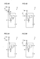
- Figs. 3A and 3B are equivalent circuit diagrams of a portable radio according to a third embodiment of the present invention.
- Figs. 4A and 4B are diagrams schematically showing a portable radio according to a fourth embodiment of the present invention.
- Figs. 5A and 5B are diagrams schematically showing a portable radio according to a fifth embodiment of the present invention.
- Figs. 6A and 6B are diagrams schematically showing a portable radio according to a sixth embodiment of the present invention.
- Fig. 7 is a graph showing a measurement result of antenna coupling in the portable radio of the present invention.
-
- Now, the embodiments of the present invention will be described with reference to Figs. 1A to 7.
- Figs. 1A to 1D show a portable radio or a
mobile radio set 1 such as a portable radio telephone of the first embodiment of the present invention as well as modifications thereof. Fig. 1E is a side view of the internal antenna shown in Fig. 1A. - As shown in Fig. 1A,
portable radio 1 includes acasing 2, afirst antenna 3, asecond antenna 4, aswitch 5, and a power supply means 6. - As shown in Fig. 1E, casing 2 contains a
ground substrate 13 on whichsecond antenna 4 is mounted. First antenna is preferably a monopole antenna, which can be freely pulled out from and pushed incasing 2. A length L1 offirst antenna 3 is an integral (at least 1) multiple of a half wavelength (λ). Thus, the current to casing 2 can be controlled when pulling out. -
Second antenna 4 is contained incasing 2 and is preferably a short patch antenna.Second antenna 4 is rectangular when viewed from above in Fig. 1A, having at oneend 4a a short-circuit board 12, and is connected tosubstrate 13 through short-circuit board 12. In addition,second antenna 4 has a length L2 in the width direction ofcasing 2 of for example λ/4. - The present inventor has found that the combination of first
linear antenna 3 and second plate-like antenna 4 connected to groundsubstrate 13 provides smaller antenna coupling (about -20dB to -30dB) in the applied band as shown in Fig. 7 although the antennae are maintained fairly dose to each other despite a large wavelength. Thus, the inefficiency problem due to an interference between antennas can be alleviated. - Further, the above mentioned second plate-
like antenna 4 provides a radiation field by the combination of currents flowing through a portion parallel toground substrate 13 and short-circuit board 12. As a result, omnidirectionality is obtained in the plane including the direction normal to the substrate and the direction from short-circuit board 12 toward the power supply point side, when viewing the substrate from above as a rectangular shape. - Further, since
second antenna 4 is laterally arranged as shown in Fig. 1A,second antenna 4 does not have directionality in the plane orthogonal to the longitudinal direction of the casing and polarized waves become orthogonal to the longitudinal direction of the casing. Thus, when mounted obliquely to the human body, the polarized waves become generally vertical to the ground, whereby polarized wave alignment with respect to the base station of the vertically polarized waves is improved. - On the other hand,
second antenna 4 may be longitudinally arranged as shown in Fig. 1D. Thus,second antenna 4 has omnidirectionality in the plane including the longitudinal direction of the casing and the direction normal to the substrate, and the polarization plane becomes parallel to the longitudinal direction of the casing. As a result, when operating a terminal device while looking at a data display portion on the casing or the like, favorable polarized wave alignment is ensured with respect to the base station of the vertically polarized waves regardless of the tilt angle. - Note that the short-circuit point of
second antenna 4 as shown in Fig. 1D may be at any of the upper and lower portions. Further, the shape ofsecond antenna 4 can be arbitrarily selected if it causes a desired electric field in the space betweensecond antenna 4 andsubstrate 13. Moreover, a plate-like antenna such as a patch antenna can be employed as an internal antenna of the present invention. -
Switch 5 can selectively connectsfirst antenna 3 andsecond antenna 4 to power supply means 6 throughcontacts first antenna 3 andsecond antenna 4 are selectively excited. - More specifically, referring to Fig. 1C,
first antenna 3 and power supply means 6 are connected when pulling outfirst antenna 3, andsecond antenna 4 and power supply means 6 are connected when pushing infirst antenna 3. Thus,first antenna 3 is used for communication when it is pulled out, and second antenna is used for communication whenfirst antenna 3 is pushed in. - As shown in Fig. 1B,
first antenna 3 preferably extends in the direction away fromhuman body 7. In this way, the performance degradation of the antenna due to the human body may be alleviated. - Now, referring to Figs. 2A and 2B, the second embodiment of the present invention will be described.
- As shown in Fig. 2A, in the second embodiment, a
flip 8 is provided incasing 2 capable of being freely opened and closed, andfirst antenna 3 is provided inflip 8. The other parts of the structure are the same as in the example shown in Fig. 1A. - As in the first embodiment, the present embodiment would provide smaller coupling of first and
second antennae -
First antenna 3 is typically contained inflip 8. For providingfirst antenna 3 inflip 8, a method disclosed in Japanese Patent Laying-Open No. 8-186518 may be employed. -
Switch 5 connects power supply means 6 tofirst antenna 3 whenflip 8 is opened, and connects power supply means 6 tosecond antenna 4 whenflip 8 is dosed. Thus,first antenna 3 is used for communication whenflip 8 is opened, andsecond antenna 4 is used for communication whenflip 8 is closed. - As shown in Fig. 2B,
flip 8 preferably extends in the direction away fromhuman body side 7 whenflip 8 is opened. Thus,first antenna 3 is held away from the human body. - Now, referring to Figs. 3A and 3B, the third embodiment of the present invention will be described. Fig. 3A shows that
first antenna 3 is excited, and Fig. 3B shows thatsecond antenna 4 is excited. - As shown in Figs. 3A and 3B, in the third embodiment, switches 9 and 10 are provided. When
first antenna 3 is pulled out, for example as shown in Fig. 3A,first antenna 3 is excited andsecond antenna 4 is connected to a load impedance Z2. Thus, the phase of waves reflected bysecond antenna 4 can be controlled, whereby beam deformation or efficiency decrease offirst antenna 3 is suppressed. - When
first antenna 3 is pushed in, for example as shown in Fig. 3B,second antenna 4 is excited andfirst antenna 3 is connected to load impedance Z1. In this case also, beam deformation or efficiency decrease ofsecond antenna 3 is suppressed. - Note that the concept of the third embodiment is applicable to the portable radio shown in Figs. 2A and 2B. In this case, when
flip 8 is opened,first antenna 3 is excited andsecond antenna 4 is connected to load impedance Z2. Whenflip 8 is closed,second antenna 4 is excited andfirst antenna 3 is connected to load impedance Z1. - Now, referring to Figs. 4A and 4B, the fourth embodiment of the present invention will be described.
- As shown in Figs. 4A and 4B, in the fourth embodiment,
first antenna 3 has amonopole antenna 3a and ahelical antenna 3b.Monopole antenna 3a andhelical antenna 3b are arranged in series. - Thus,
monopole antenna 3a is used whenmonopole antenna 3a is pulled out, andhelical antenna 3b is used whenmonopole antenna 3a is pushed in. - The fourth embodiment produces the same effect as the first embodiment. Further, in the fourth embodiment,
second antenna 4 is excited both whenmonopole antenna 3a is pulled out and pushed in. Accordingly,monopole antenna 3a andsecond antenna 4 are both excited whenmonopole antenna 3a is pulled out, andhelical antenna 3b andsecond antenna 4 are both excited whenmonopole antenna 3a is pushed in. - In the antenna of the present invention, a power supply circuit for exciting two
antennae second antennae second antennae - Here, an excitation method when first and
second antennae first antenna 3 is defined as V, and that for excitingsecond antenna 4 is defined as H. - When a ratio of the above mentioned power levels V and H (V:H) is 1:0, vertically polarized waves can be generated. When V:H is 0.5:0.5, waves polarized by 45° can be generated. When V:H is 0:1, horizontally polarized waves can be generated. Thus, by controlling the ratio of power levels V and H, the polarized waves can be freely changed.
- Note that the concept of the fourth embodiment is applicable to the portable radio shown in Figs. 2A and 2B. In this case, first ant
second antennae closing flip 8. - Now, referring to Figs. 5A and 5B, the fifth embodiment of the present invention will be described.
- As shown in Figs. 5A and 5B, in the fifth embodiment, only
first antenna 3 is excited whenfirst antenna 3 is pulled out, andhelical antenna 3b andsecond antenna 4 are both excited whenfirst antenna 3 is pushed in. - According to the fifth embodiment, the same effect as in the first embodiment is produced and, when first and
second antennae - Note that the concept of the fifth embodiment is applicable to the portable radio shown in Figs. 2A and 2B. In this case, only
first antenna 3 is excited whenflip 8 is opened, and first andsecond antennae flip 8 is closed. - Now, referring to Figs. 6A and 6B, the sixth embodiment of the present invention will be described.
- As shown in Figs. 6A and 6B, in the sixth embodiment,
first antenna 3 andsecond antenna 4 are both excited whenfirst antenna 3 is pulled out, and onlysecond antenna 4 is excited whenfirst antenna 3 is pushed in. - According to the sixth embodiment, the same effect as in the first embodiment is produced and, when first and
second antennae - Note that the concept of the sixth embodiment is applicable to the portable radio shown in Figs. 2A and 2B. In this case, first and
second antennae flip 8 is opened, and onlysecond antenna 4 is excited whenflip 8 is closed. - As in the foregoing, although the embodiments of the present invention have been described, the features of the embodiments can be combined where appropriate. Further, it should be understood that the embodiments herein disclosed is by way of illustration only and is not to be taken by way of limitation. The scope of the present invention is limited only by the terms of the appended claim and may include all variations in the scope equivalent in meaning to the claims.
- The present invention can be effectively applied to a portable radio provided with at least two types of antennae.
Claims (15)
- A portable radio, comprising:a casing (2);a first linear antenna (3) capable of being pulled out from said casing (2);a second plate-like antenna (4) contained in said casing (2) and connected to a ground substrate (13); andpower supply means (6) for exciting at least one of said first antenna (3) and said second antenna (4).
- The portable radio according to claim 1, further comprising switching means (5) between said first antenna (3) and said second antenna (4), and said power supply means (6).
- The portable radio according to claim 2, wherein said switching means (5) connects said first antenna (3) and said power supply means (6) when said first antenna (3) is pulled out, and connects said second antenna (4) and said power supply means (6) when said first antenna (3) is pushed in.
- The portable radio according to claim 2, wherein said switching means (5) connects both said first antenna (3) and said second antenna (4) to said power supply means (6) when said first antenna (3) is pulled out, and connects said second antenna (4) and said power supply means (6) when said first antenna (3) is pushed in.
- The portable radio according to claim 2, wherein said switching means (5) connects both said first antenna (3) and said second antenna (4) to said power supply means (6) when said first antenna (3) is pulled out, and also connects both said first antenna (3) and said second antenna (4) when said first antenna (3) is pushed in.
- The portable radio according to claim 2, wherein said switching means (5) connects said first antenna (3) to said power supply means (6) when said first antenna (3) is pulled out, and connects both said first antenna (3) and said second antenna (4) to said power supply means (6) when said first antenna (3) is pushed in.
- The portable radio according to claim 1, wherein said first antenna (3) includes a monopole antenna having a length of an integral multiple of a half wave, and said second antenna (4) includes a short patch antenna.
- The portable radio according to claim 7, wherein said first antenna (3) includes a helical antenna arranged in series with said monopole antenna.
- The portable radio according to claim 1, wherein said first antenna (3) is obliquely arranged toward a side opposite a human body.
- A portable radio, comprising:a casing (2) having a flip (8);a first antenna (14) provided in said flip (8);a second plate-like antenna (4) contained in said casing (2) and connected to a ground substrate (13); andpower supply means (6) for exciting at least one of said first antenna (3) and said second antenna (4).
- The portable radio according to claim 10, further comprising switching means (5) between said first antenna (3) and said second antenna (4), and said power supply means (6).
- The portable radio according to claim 11, wherein said switching means (5) connects said first antenna (3) to said power supply means (6) when said flip (8) is opened, and connects said second antenna (4) and said power supply means (6) when said flip (8) is dosed.
- The portable radio according to claim 11, wherein said switching means (5) connects both said first antenna (3) and said second antenna (4) to said power supply means (6) when said flip (8) is opened, and connects said second antenna (4) and said power supply means (6) when said flip (8) is closed.
- The portable radio according to claim 11, wherein said switching means (5) connects both said first antenna (3) and said second antenna (4) to said power supply means (6) when said flip (8) is opened, and also connects both said first antenna (3) and said second antenna (4) to said power supply means (6) when said flip (8) is closed.
- The portable radio according to claim 11, wherein said switching means (5) connects said first antenna (3) and said power supply means (6) when said flip (8) is opened, and connects both said first antenna (3) and said second antenna (4) to said power supply means when said flip (8) is closed.
Applications Claiming Priority (1)
| Application Number | Priority Date | Filing Date | Title |
|---|---|---|---|
| PCT/JP2000/002607 WO2001082407A1 (en) | 2000-04-20 | 2000-04-20 | Portable radio device |
Publications (1)
| Publication Number | Publication Date |
|---|---|
| EP1289049A1 true EP1289049A1 (en) | 2003-03-05 |
Family
ID=11735950
Family Applications (1)
| Application Number | Title | Priority Date | Filing Date |
|---|---|---|---|
| EP00917400A Withdrawn EP1289049A1 (en) | 2000-04-20 | 2000-04-20 | Portable radio device |
Country Status (3)
| Country | Link |
|---|---|
| EP (1) | EP1289049A1 (en) |
| CN (1) | CN1357162A (en) |
| WO (1) | WO2001082407A1 (en) |
Cited By (1)
| Publication number | Priority date | Publication date | Assignee | Title |
|---|---|---|---|---|
| WO2014148834A1 (en) | 2013-03-20 | 2014-09-25 | Samsung Electronics Co., Ltd. | Antenna, user terminal apparatus, and method of controlling antenna |
Family Cites Families (9)
| Publication number | Priority date | Publication date | Assignee | Title |
|---|---|---|---|---|
| JPS6142148U (en) * | 1984-08-23 | 1986-03-18 | 三菱電機株式会社 | portable radio |
| JP2601111Y2 (en) * | 1993-10-14 | 1999-11-08 | 京セラ株式会社 | Portable radio |
| JP3383046B2 (en) * | 1993-12-28 | 2003-03-04 | 株式会社東芝 | Wireless device |
| US5561436A (en) * | 1994-07-21 | 1996-10-01 | Motorola, Inc. | Method and apparatus for multi-position antenna |
| US5649306A (en) * | 1994-09-16 | 1997-07-15 | Motorola, Inc. | Portable radio housing incorporating diversity antenna structure |
| JPH09294103A (en) * | 1996-04-25 | 1997-11-11 | Sony Corp | Antenna device and portable wireless device |
| JP3667517B2 (en) * | 1997-12-16 | 2005-07-06 | 埼玉日本電気株式会社 | Mobile phone |
| JP3467752B2 (en) * | 1998-03-18 | 2003-11-17 | Necトーキン株式会社 | Mobile communication terminal and its antenna device |
| JP2000049649A (en) * | 1998-07-24 | 2000-02-18 | Matsushita Electric Ind Co Ltd | Antenna device |
-
2000
- 2000-04-20 EP EP00917400A patent/EP1289049A1/en not_active Withdrawn
- 2000-04-20 CN CN00809254.0A patent/CN1357162A/en active Pending
- 2000-04-20 WO PCT/JP2000/002607 patent/WO2001082407A1/en not_active Ceased
Non-Patent Citations (1)
| Title |
|---|
| See references of WO0182407A1 * |
Cited By (3)
| Publication number | Priority date | Publication date | Assignee | Title |
|---|---|---|---|---|
| WO2014148834A1 (en) | 2013-03-20 | 2014-09-25 | Samsung Electronics Co., Ltd. | Antenna, user terminal apparatus, and method of controlling antenna |
| EP2976807A4 (en) * | 2013-03-20 | 2016-11-16 | Samsung Electronics Co Ltd | ANTENNA, USER TERMINAL APPARATUS, AND ANTENNA CONTROL METHOD |
| US10305181B2 (en) | 2013-03-20 | 2019-05-28 | Samsung Electronics Co., Ltd. | Antenna, user terminal apparatus, and method of controlling antenna |
Also Published As
| Publication number | Publication date |
|---|---|
| CN1357162A (en) | 2002-07-03 |
| WO2001082407A1 (en) | 2001-11-01 |
Similar Documents
| Publication | Publication Date | Title |
|---|---|---|
| US6683573B2 (en) | Multi band chip antenna with dual feeding ports, and mobile communication apparatus using the same | |
| US6856819B2 (en) | Portable wireless unit | |
| KR101054713B1 (en) | Multiband Multimode Compact Antenna System | |
| US6606071B2 (en) | Multifrequency antenna with a slot-type conductor and a strip-shaped conductor | |
| US20050104783A1 (en) | Antenna for portable radio | |
| JP2004056421A (en) | Antenna device and portable radio communication terminal | |
| JP2011041261A (en) | Antenna device | |
| JPH11317616A (en) | Directional antenna for mobile telephone | |
| KR20090031969A (en) | Antenna element and broadband antenna device | |
| US10374311B2 (en) | Antenna for a portable communication device | |
| JP4171008B2 (en) | Antenna device and portable radio | |
| EP1962372B1 (en) | Miniature broadband antenna with inductive chassis coupling | |
| JP2004112044A (en) | Loop antenna | |
| EP1280226A1 (en) | Portable radio device | |
| EP1643588A1 (en) | Portable radio | |
| JPH09232849A (en) | Shared antenna and portable wireless device using the same | |
| EP1289049A1 (en) | Portable radio device | |
| EP2063487A1 (en) | Dual band antenna | |
| US7808436B2 (en) | Folding type communication terminal device | |
| EP4207492A1 (en) | Compact multi-band antenna | |
| EP1887649A1 (en) | Portable wireless apparatus | |
| JP2004120519A (en) | Antenna for portable radio | |
| Joshi et al. | Dual band antenna for portable consumer devices | |
| Wong et al. | Bandwidth enhancement of small‐size internal WWAN laptop computer antenna using a resonant open slot embedded in the ground plane | |
| KR100691997B1 (en) | Chip Antenna of Mobile Communication Terminal |
Legal Events
| Date | Code | Title | Description |
|---|---|---|---|
| PUAI | Public reference made under article 153(3) epc to a published international application that has entered the european phase |
Free format text: ORIGINAL CODE: 0009012 |
|
| 17P | Request for examination filed |
Effective date: 20020117 |
|
| AK | Designated contracting states |
Kind code of ref document: A1 Designated state(s): AT BE CH CY DE DK ES FI FR GB GR IE IT LI LU MC NL PT SE Designated state(s): AT BE CH CY DE DK ES FI FR GB GR IE IT LI LU MC NL PT SE |
|
| RBV | Designated contracting states (corrected) |
Designated state(s): DE FR GB |
|
| STAA | Information on the status of an ep patent application or granted ep patent |
Free format text: STATUS: THE APPLICATION HAS BEEN WITHDRAWN |
|
| 18W | Application withdrawn |
Effective date: 20050119 |