EP1288999A2 - Double ellipsoid light bulb using total internal reflection - Google Patents
Double ellipsoid light bulb using total internal reflection Download PDFInfo
- Publication number
- EP1288999A2 EP1288999A2 EP02078558A EP02078558A EP1288999A2 EP 1288999 A2 EP1288999 A2 EP 1288999A2 EP 02078558 A EP02078558 A EP 02078558A EP 02078558 A EP02078558 A EP 02078558A EP 1288999 A2 EP1288999 A2 EP 1288999A2
- Authority
- EP
- European Patent Office
- Prior art keywords
- light
- source
- light bulb
- focal point
- walls
- Prior art date
- Legal status (The legal status is an assumption and is not a legal conclusion. Google has not performed a legal analysis and makes no representation as to the accuracy of the status listed.)
- Withdrawn
Links
- 239000011521 glass Substances 0.000 claims description 5
- 230000009977 dual effect Effects 0.000 description 6
- 239000003795 chemical substances by application Substances 0.000 description 4
- 239000007787 solid Substances 0.000 description 3
- 239000000654 additive Substances 0.000 description 2
- 239000003086 colorant Substances 0.000 description 2
- 239000000835 fiber Substances 0.000 description 2
- 238000012986 modification Methods 0.000 description 2
- 230000004048 modification Effects 0.000 description 2
- VYPSYNLAJGMNEJ-UHFFFAOYSA-N silicon dioxide Inorganic materials O=[Si]=O VYPSYNLAJGMNEJ-UHFFFAOYSA-N 0.000 description 2
- NIXOWILDQLNWCW-UHFFFAOYSA-N acrylic acid group Chemical group C(C=C)(=O)O NIXOWILDQLNWCW-UHFFFAOYSA-N 0.000 description 1
- 239000004020 conductor Substances 0.000 description 1
- 238000010276 construction Methods 0.000 description 1
- 239000005331 crown glasses (windows) Substances 0.000 description 1
- 230000000694 effects Effects 0.000 description 1
- 230000002349 favourable effect Effects 0.000 description 1
- 239000012530 fluid Substances 0.000 description 1
- 239000005350 fused silica glass Substances 0.000 description 1
- WABPQHHGFIMREM-UHFFFAOYSA-N lead(0) Chemical compound [Pb] WABPQHHGFIMREM-UHFFFAOYSA-N 0.000 description 1
- 239000000463 material Substances 0.000 description 1
- 239000004033 plastic Substances 0.000 description 1
- 239000004417 polycarbonate Substances 0.000 description 1
- 229920000515 polycarbonate Polymers 0.000 description 1
- 239000010453 quartz Substances 0.000 description 1
- 239000012780 transparent material Substances 0.000 description 1
Images



Classifications
-
- H—ELECTRICITY
- H01—ELECTRIC ELEMENTS
- H01K—ELECTRIC INCANDESCENT LAMPS
- H01K1/00—Details
- H01K1/28—Envelopes; Vessels
-
- H—ELECTRICITY
- H01—ELECTRIC ELEMENTS
- H01J—ELECTRIC DISCHARGE TUBES OR DISCHARGE LAMPS
- H01J61/00—Gas-discharge or vapour-discharge lamps
- H01J61/02—Details
- H01J61/30—Vessels; Containers
Definitions
- the present invention relates generally to light emitting devices, and more particularly to a total internal reflection light bulb.
- the present invention provides a light bulb using total internal reflection to provide more efficient focused output.
- the body of the light bulb is arranged having walls extending in an elliptical contour from a central focal plane to opposite ends.
- a light source includes a light-emitting medium or filament that extends between oppositely extending electrodes and is positioned to axially extend across a central cavity of the body.
- the light bulb includes a solid body portion having a central cavity.
- the central cavity includes rare earths or additives used to produce different colors according to the application.
- the outer walls of the solid body portion extend elliptically in opposite directions to provide total internal reflection. Light emitted from the light source reflects off the outer walls of the light bulb and is directed toward the focus of each elliptical half of the bulb.
- Figure 1 is a perspective view of the dual ellipsoid light bulb according to a first embodiment
- Figure 2 is a perspective view of the dual ellipsoid light bulb according to a second embodiment
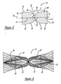
- Figure 3 is a sectional side view of a dual ellipsoid light bulb along line III-III of Figure 1;
- Figure 4 is a ray trace of the light bulb of the first embodiment
- Figure 5 illustrates a basic ellipse
- Figure 6 is a semi-ellipse illustrating a ray trace having total internal reflection according to the teachings of this invention
- Figure 7 is a side view of the dual ellipsoid light bulb according to a second embodiment.
- Figure 8 is a ray trace of the light bulb of the second embodiment.
- the light bulb 10 is defined by body 20 having walls 22 and includes a light source 12 disposed therein.
- the light source 12 is positioned between electrodes 14.
- Body 20 is configured to allow light 50 emitted from light source 12 to reflect off walls 22 by total internal reflection.
- Walls 22 are defined by overlapping semi-ellipsoids 32, 34, which are generally ellipsoids truncated at their axis of symmetry. As such, walls 22 extend toward opposite ends 36, 38 from a first equatorial plane 40 extending through the diameter of central spherical cavity 42. First equatorial plane 40 is equidistant from opposite ends 36, 38. The location of opposite ends 36, 38 is determined by the semi-minor axis "B" of each overlapping ellipsoid 32, 34.
- Body 20 is comprised of solid transparent material such as glass.
- Body 20 may also be composed of quartz, fused silica, crown glass, plastic (acrylic, polycarbonate), or any other suitable material.
- Central spherical cavity 42 is filled with fluid such as rare earths or additives used to produce different light colors or effects according to the desired application.
- Light source 12 such as a filament, arc, or plasma, is maintained between oppositely extending electrodes 14 which suspend the light source 12 across a second equatorial plane 48 coincident with electrodes 14 through spherical cavity 42.
- light source 12 perpendicularly intersects first equatorial plane 40.
- Such an alignment promotes total internal reflection of light emitted from light source 12 off walls 22 of body 20 to opposite ends 36, 38.
- the alignment of overlapping first and second semi-ellipsoid geometries 32, 34 is determined according to the coincidal of the associated focal point "C" for each ellipsoid 32, 34.
- the basic ellipse includes x and y axis intersecting at a point ⁇ .
- the y axis intersects the basic ellipse at points y1 and y2, and the x axis intersects the basic ellipse at points x1 and x2.
- a semi-major axis A extends between points ⁇ and x2.
- a semi-minor axis B extends between point ⁇ and y1.
- the basic ellipse provides focal points F1 and F2.
- a distance C extends between point ⁇ and F2.
- half of the basic ellipse shown in Figure 6 is truncated at one end through a plane extending through its focal point.
- one-half of a basic ellipse is shown with a truncated end in planar alignment with focal point F1.
- a target 30, such as a fiber bundle or light pipe, is positioned at focal point F2 for the basic elliptical shape.
- the gausian intensity distribution is shown at reference 44. From this basic shape and basic ellipse equation above, the diameter of the illuminated zone D I can be determined according to the following equation, where D spot , or the diameter of target 30, equals one-half D I and AG is the arc gap or filament length.
- FIG 4 a ray trace model illustrating the light 50 emitted from bulb 10 is shown. Opposite ends 36, 38 are oriented to allow light transfer devices such as fiber optic bundles or light pipes to be attached thereto.
- bulb 10 constructed in accordance to a second embodiment is illustrated.
- the use and construction of bulb 10' has many common aspects as compared to the bulb 10 of the first embodiment. Accordingly, like reference numerals have been used in the drawings to identify substantially identical features of the embodiments.
- Bulb 10' includes walls extending in an elliptical contour outwardly from a plane dividing central spherical cavity.
- the elliptical contour extends on each side to an intermediate plane defined by the semi-minor axis "B"' of each overlapping semi-ellipsoid 32', 34'.
- Electrodes 14' are arranged to extend outwardly toward opposite ends 36', 38' to axis "B"' whereby the electrodes extend along axis "B"' to walls 22'.
- the electrodes are conductors that carry the current from a lead wire (not shown) through the body 20' into the spherical cavity 42'.
- the walls 22' conically extend from each semi-minor axis "B"' toward opposite ends 36', 38' defining conical end portions 52, 54.
- the conical end portions 52, 54 provide a mounting structure which is favorable in certain applications.
- Figure 8 is a ray trace of bulb 10'.
- Light rays 50' reflect off walls 22' and are directed toward opposite ends 36', 38'.
- Rays 60 represent minimal inefficiencies which would not enter the bundle.
Landscapes
- Non-Portable Lighting Devices Or Systems Thereof (AREA)
Abstract
Description

Claims (15)
- A light emitting apparatus comprising:wherein the walls of said body cause total internal reflection of light emitted from said source focal point to said target focal points.a body having walls defining a source focal point within said body and target focal points adjacent opposite ends of said body; anda light source disposed within said body at said source focal point;
- The light emitting apparatus of claim 1, wherein said light source includes a filament.
- The light emitting apparatus of claim 1, wherein said light source extends between two electrodes.
- The light emitting apparatus of claim 1, wherein said body further comprises glass.
- The light emitting apparatus of claim 1, wherein said body is further defined by a central cavity at said source focal point.
- A light bulb for reflecting internally generated light, said light bulb comprising:a body having walls defining a source focal point within said body and target focal points adjacent opposite ends of said body, said walls defined by a first and second overlapping semi-ellipsoids, said opposite ends defined by conical end portions extending from said semi-ellipsoids; anda light source disposed within said body at said source focal point, said walls of said body causing total internal reflection of light emitted from said light source to said target focal points.
- The light bulb of claim 6, wherein said light source includes a filament.
- The light bulb of claim 7, wherein said light source extends between two electrodes.
- The light bulb of claim 8, wherein said body further comprises glass.
- The light bulb of claim 6, wherein said body is further defined by a central cavity at said source focal point.
- A light bulb comprising:a body having walls defined by a first and second overlapping semi-ellipsoids, said first and second semi-ellipsoids each having distal ends opposite a first focal point and a target focal point proximate each said distal end, said first and second semi-ellipsoids overlapping with said first focal points coinciding to define a source focal point and said distal ends diametrically opposed; anda light source supported by said body at said source focal point, said walls causing total internal reflection of light emitted by said source to focus at said target focal points.
- The light bulb of claim 11, wherein said first and second ends are defined by a semi-minor axis of said first and second semi-ellipsoids.
- The light bulb of claim 11, wherein said light source includes a filament.
- The light bulb of claim 11, wherein said light source extends between two electrodes.
- The light bulb of claim 14, wherein said body further comprises glass.
Applications Claiming Priority (2)
| Application Number | Priority Date | Filing Date | Title |
|---|---|---|---|
| US943783 | 2001-08-31 | ||
| US09/943,783 US20030057812A1 (en) | 2001-08-31 | 2001-08-31 | Double ellipsoid light bulb using total internal reflection |
Publications (2)
| Publication Number | Publication Date |
|---|---|
| EP1288999A2 true EP1288999A2 (en) | 2003-03-05 |
| EP1288999A3 EP1288999A3 (en) | 2006-05-03 |
Family
ID=25480250
Family Applications (1)
| Application Number | Title | Priority Date | Filing Date |
|---|---|---|---|
| EP02078558A Withdrawn EP1288999A3 (en) | 2001-08-31 | 2002-08-29 | Double ellipsoid light bulb using total internal reflection |
Country Status (2)
| Country | Link |
|---|---|
| US (1) | US20030057812A1 (en) |
| EP (1) | EP1288999A3 (en) |
Cited By (2)
| Publication number | Priority date | Publication date | Assignee | Title |
|---|---|---|---|---|
| CN108681644A (en) * | 2018-05-21 | 2018-10-19 | 河海大学常州校区 | A method of the prediction welding heat affected sector width of double wire hidden arc welding |
| CN108681643A (en) * | 2018-05-21 | 2018-10-19 | 河海大学常州校区 | A kind of prediction technique of monofilament submerged arc welding heat affected area width |
Family Cites Families (7)
| Publication number | Priority date | Publication date | Assignee | Title |
|---|---|---|---|---|
| US2362176A (en) * | 1943-03-25 | 1944-11-07 | Swanson Harold | Flashlight full-beam electric lamp |
| CA1179726A (en) * | 1980-09-09 | 1984-12-18 | Duro-Test Corporation | Incandescent lamp with infrared reflecting coating and with envelope made of several sections and method of manufacturing same |
| DE4341555C2 (en) * | 1992-12-28 | 1996-07-04 | Ford Motor Co | Device for bundling and transmitting light |
| DE4420607A1 (en) * | 1994-06-13 | 1995-12-14 | Patent Treuhand Ges Fuer Elektrische Gluehlampen Mbh | Electric incandescent lamp and filament for incandescent lamps |
| DE19701792A1 (en) * | 1997-01-20 | 1998-07-23 | Patent Treuhand Ges Fuer Elektrische Gluehlampen Mbh | Incandescent lamp with reflective coating |
| US6304693B1 (en) * | 1999-12-02 | 2001-10-16 | Fiberstars Incorporated | Efficient arrangement for coupling light between light source and light guide |
| JP2001283614A (en) * | 2000-03-31 | 2001-10-12 | Stanley Electric Co Ltd | LIGHT CONDUCT, LIGHT CONDUCTIVE APPARATUS, VEHICLE LIGHT CONDUCTOR, VEHICLE LIGHT EQUIPPED WITH LIGHT CONDUCTIVE APPARATUS |
-
2001
- 2001-08-31 US US09/943,783 patent/US20030057812A1/en not_active Abandoned
-
2002
- 2002-08-29 EP EP02078558A patent/EP1288999A3/en not_active Withdrawn
Cited By (2)
| Publication number | Priority date | Publication date | Assignee | Title |
|---|---|---|---|---|
| CN108681644A (en) * | 2018-05-21 | 2018-10-19 | 河海大学常州校区 | A method of the prediction welding heat affected sector width of double wire hidden arc welding |
| CN108681643A (en) * | 2018-05-21 | 2018-10-19 | 河海大学常州校区 | A kind of prediction technique of monofilament submerged arc welding heat affected area width |
Also Published As
| Publication number | Publication date |
|---|---|
| US20030057812A1 (en) | 2003-03-27 |
| EP1288999A3 (en) | 2006-05-03 |
Similar Documents
| Publication | Publication Date | Title |
|---|---|---|
| US5117312A (en) | Apparatus including concave reflectors and a line of optical fibers | |
| US6899443B2 (en) | Light module | |
| US6418253B2 (en) | High efficiency reflector for directing collimated light into light guides | |
| US6128431A (en) | High efficiency source coupler for optical waveguide illumination system | |
| CN1237359C (en) | Optical system including coupler for transmitting light between a single fiber light guide and multiple single fiber light guides | |
| US5481637A (en) | Hollow light guide for diffuse light | |
| US5271077A (en) | Nonimaging reflector for coupling light into a light pipe | |
| US20020122621A1 (en) | Coupling of light from a non-circular light source | |
| US6937791B2 (en) | Optical coupling apparatus and method | |
| JP2007513382A (en) | Reflected light coupler | |
| US6827475B2 (en) | LED light collection and uniform transmission system | |
| KR100638227B1 (en) | Lighting system using filament lamp | |
| CN1211604C (en) | Electromagnetic Radiation Concentration and Collection Systems | |
| JPH07114809A (en) | Lighting system | |
| CN107533157B (en) | Light-beam forming unit and the spotlight for using light-beam forming unit | |
| US6619820B2 (en) | Light condensing and collecting systems using lensed light pipes | |
| US10267473B2 (en) | Lighting device for vehicle having a reflective fluorescent body and prism | |
| US11635604B2 (en) | Luminous flux collector for directing light into a light-diffusing fiber | |
| JP2012502320A (en) | Pseudo light pipe for coupling of double paraboloidal reflector (DPR) | |
| CN102792196A (en) | Light guide focussing device and method | |
| JPH09325234A (en) | Optical coupling device | |
| JPS62116918A (en) | Photoconverter | |
| US11313527B2 (en) | Illumination device | |
| US20030057812A1 (en) | Double ellipsoid light bulb using total internal reflection | |
| JPH0521043A (en) | Lighting equipment |
Legal Events
| Date | Code | Title | Description |
|---|---|---|---|
| PUAI | Public reference made under article 153(3) epc to a published international application that has entered the european phase |
Free format text: ORIGINAL CODE: 0009012 |
|
| AK | Designated contracting states |
Kind code of ref document: A2 Designated state(s): AT BE BG CH CY CZ DE DK EE ES FI FR GB GR IE IT LI LU MC NL PT SE SK TR Designated state(s): AT BE BG CH CY CZ DE DK EE ES FI FR GB GR IE IT LI LU MC NL PT SE SK TR |
|
| AX | Request for extension of the european patent |
Extension state: AL LT LV MK RO SI |
|
| PUAL | Search report despatched |
Free format text: ORIGINAL CODE: 0009013 |
|
| AK | Designated contracting states |
Kind code of ref document: A3 Designated state(s): AT BE BG CH CY CZ DE DK EE ES FI FR GB GR IE IT LI LU MC NL PT SE SK TR |
|
| AX | Request for extension of the european patent |
Extension state: AL LT LV MK RO SI |
|
| STAA | Information on the status of an ep patent application or granted ep patent |
Free format text: STATUS: THE APPLICATION IS DEEMED TO BE WITHDRAWN |
|
| 18D | Application deemed to be withdrawn |
Effective date: 20060302 |