EP1288888A2 - A method and system for improving situational awareness of command and control units - Google Patents
A method and system for improving situational awareness of command and control units Download PDFInfo
- Publication number
- EP1288888A2 EP1288888A2 EP02405414A EP02405414A EP1288888A2 EP 1288888 A2 EP1288888 A2 EP 1288888A2 EP 02405414 A EP02405414 A EP 02405414A EP 02405414 A EP02405414 A EP 02405414A EP 1288888 A2 EP1288888 A2 EP 1288888A2
- Authority
- EP
- European Patent Office
- Prior art keywords
- command
- control unit
- reference map
- image
- digital reference
- Prior art date
- Legal status (The legal status is an assumption and is not a legal conclusion. Google has not performed a legal analysis and makes no representation as to the accuracy of the status listed.)
- Granted
Links
Images

Classifications
-
- G—PHYSICS
- G01—MEASURING; TESTING
- G01M—TESTING STATIC OR DYNAMIC BALANCE OF MACHINES OR STRUCTURES; TESTING OF STRUCTURES OR APPARATUS, NOT OTHERWISE PROVIDED FOR
- G01M11/00—Testing of optical apparatus; Testing structures by optical methods not otherwise provided for
- G01M11/02—Testing optical properties
- G01M11/04—Optical benches therefor
-
- G—PHYSICS
- G01—MEASURING; TESTING
- G01C—MEASURING DISTANCES, LEVELS OR BEARINGS; SURVEYING; NAVIGATION; GYROSCOPIC INSTRUMENTS; PHOTOGRAMMETRY OR VIDEOGRAMMETRY
- G01C21/00—Navigation; Navigational instruments not provided for in groups G01C1/00 - G01C19/00
- G01C21/38—Electronic maps specially adapted for navigation; Updating thereof
- G01C21/3804—Creation or updating of map data
- G01C21/3807—Creation or updating of map data characterised by the type of data
- G01C21/3811—Point data, e.g. Point of Interest [POI]
-
- G—PHYSICS
- G01—MEASURING; TESTING
- G01C—MEASURING DISTANCES, LEVELS OR BEARINGS; SURVEYING; NAVIGATION; GYROSCOPIC INSTRUMENTS; PHOTOGRAMMETRY OR VIDEOGRAMMETRY
- G01C21/00—Navigation; Navigational instruments not provided for in groups G01C1/00 - G01C19/00
- G01C21/38—Electronic maps specially adapted for navigation; Updating thereof
- G01C21/3804—Creation or updating of map data
- G01C21/3833—Creation or updating of map data characterised by the source of data
- G01C21/3852—Data derived from aerial or satellite images
Definitions
- the present invention relates generally to communication between command and control (C&C) units, more particularly to digital data exchange over a data link between C&C units, of visual data acquired by airborne vehicles, which are controlled by the C&C units.
- C&C command and control
- the present invention also relates to Israeli Patent No. 111069 to Sroka et al. incorporated by reference for all purposes as if fully set forth herein.
- the display may reside in the aircraft cockpit visually displaying the digital data link communications.
- the display may also be used at a ground location, such as at an air traffic control unit.
- Visually displaying the digital data link communications allows a pilot to obtain situational awareness by monitoring the digital communications between aircraft, and may be used in combination with or replace monitoring the voice communications being exchanged over the voice channels.
- U.S. Patent No. 4,682,160 to Beckwith, Jr., et al. describes a system for generating a real time perspective view of the terrain lying along an aircraft's flight path, accessing terrain data stored in a digital map generator and converting the data into a perspective representation of the terrain on the face of a suitable display such as a cockpit instrument panel CRT.
- U.S. patent No. 6,119,976 to Rogers describes a shoulder launched unmanned reconnaissance system for providing overhead visual surveillance of remote targets. That invention includes a reconnaissance air vehicle, which may be launched from a portable launcher.
- the aforementioned Israeli Patent No. 111069 to Sroka, et al. describes a method and system for marking object images acquired at high zooming by an airborne imaging device, on a reference map having a wide field of view of the scene.
- None of the prior art references addresses a situation wherein a visual status of an object whose image is acquired by one C&C unit is automatically updated in real time in all the C&C units which are connected to this C&C unit.
- Such updated information will be useful in keeping the situational awareness of the operators of the informed C&C units and will be helpful to them in reassigning new objects for airborne vehicles under their control.
- each ship controls its own squadron of aircraft.
- Each aircraft carrier is thus an autonomous command and control unit with respect to its aircraft.
- some of the ships supervise collectively the same geographical terrain territory, thus they use maps or aerial photographs in which the same targets may appear.
- the present invention fills this gap and provides other related advantages.
- the present invention includes a system and method for sharing, between a plurality of interconnected command and control units, visually rendered situational information in regard to objects under surveillance of an airborne vehicle, wherein this information is transferred in real time by a digital data-link communication.
- a method for sharing visual situational information of objects among command and control units comprising the steps of: (a) providing to each command and control unit a mechanism for storing a digital reference map of a geographical area; (b) receiving by at least one command and control unit an image of a scene which includes at least one object located within the geographical area; (c) registration of the received image of the scene to the digital reference map of the at least one command and control unit; (d) updating a situational information of the at least one object in the digital reference map of the at least one command control unit according to the received image of the scene and, (e) transferring the updating of the situational information of the at least one object to at least one other command and control unit among the plurality of command and control units.
- a system for improving the situational awareness of a plurality of command and control unit comprising: (a) a plurality of command and control units, in each command and control unit; a database located in an addressable memory of the each of command and control units, each the database storing a digital reference map of a geographical area which includes a location of at least one object under a surveillance of at least one command and control unit; (b) a mechanism for updating a situational information of the at least one object in the digital reference map stored in the at least one command and control unit in accordance to a received image of a scene which includes the at least one object, and (c) a communication mechanism between the at least one command and control unit and at least one other command and control unit.
- the purpose of the present invention is to update automatically and in real time digitally data regarding the status of an object stored by a plurality of interconnected C&C units, in accordance to an information about a situational change of the object as perceived from an image of the object which was acquired by a remote sensor controlled by one of the C&C units.
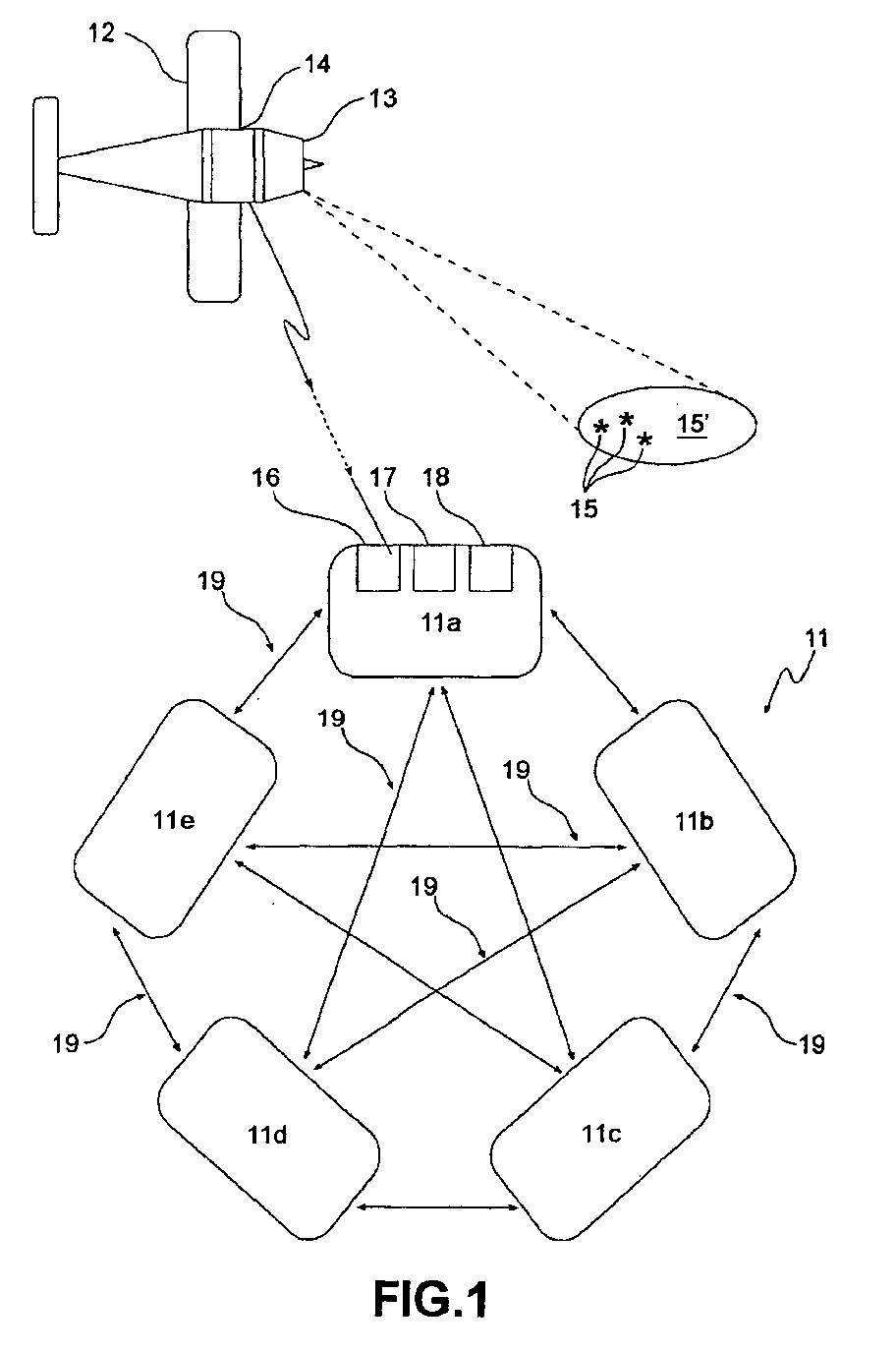
- FIG. 1 A non limiting example demonstrating the scope of the present invention is shown in FIG. 1 to which reference is now made.
- FIG. 1 shows a group 11 of 5 C&C units, 11a to 11e, interconnected to each other in such a way as to enable two-way digital data links 19 between each member of the group and the rest of the members of the group.
- the interconnection can be carried out by any networking known in the art (e.g. using physical wiring as electrical conductors, optical fibers, or via wireless communication).
- Each C&C unit in group 11 is in charge for the surveillance of a certain geographical area (not shown), by the observation or the engagement of targets in that area, preferably by remote command and control of airborne vehicles flying over that area, such as e.g. an unmanned low altitude remotely piloted vehicle 12 which is controlled by unit 11a of group 11.
- Airborne vehicle 12 carries onboard an imaging device 13 to acquire images of scene 15' which is located in the geographical area which is under the surveillance of C&C unit 11a and which includes objects 15.
- Airborne vehicle 12 carries on board a transmitting device 14, which transmits wirelessly or via an optical fiber (not shown) an image of scene 15', which was acquired by imaging device 13, to an image receiving device 16 located in C&C unit 11a.
- Image receiving device 16 reconstructs a digital image of scene 15' which include objects 15 in an addressable memory location of a computer (shown in FIG. 2, where C&C unit 11a is depicted in greater detail) of C&C unit 11a.
- Besides received digital image of object 15 is visually displayed on at least one of displays 17, 18 located in C&C unit 11a.
- Each C&C unit of group 11 stores in the database of its computer a digital image of the area, which that unit supervises; the aerial digital image includes images of objects (e.g. objects 15) that can be affected by means that are controlled by that C&C unit.
- objects e.g. objects 15
- imaging device 13 is not on board of a flying vehicle, rather it is positioned "on the ground", in such a way however, as to enable its surveillance on the neighboring scenery.
- imaging device 13 is positioned on a topographically elevated place like a hill, which looks over its underlying valley, or is posted on a high mast (either stationary or mobile).
- airborne is broadened in context with the present invention to include these situations.
- the database digital image of the area which will be referred hereinafter as the "digital reference map" is based on aerial photography (either conventional or orthogonal photography), whose output was digitized by known techniques.
- the digital reference map is constantly displayed on a suitable display device as display 18 in C&C unit 11a.
- Maps are orthogonal representations of the earth's surface, meaning that they are directionally and geometrically accurate (at least within the limitations imposed by projecting a 3-dimensional object onto 2 dimensions).
- Aerial photos display a high degree of radial distortion. That is, the topography is distorted, and until corrections are made for the distortion, measurements made from a photograph are not accurate.
- An orthogonal photograph is a result of processing of two aerial photographs taken with two cameras having their axis at the time of exposure pointing down at different angles to the normal to ground, and which like a map, it is to scale.
- the geographical location of each point in the digital reference map is known because its position vector with respect to visual features of reference landmarks on the digital reference map can be determined accurately, wherein the exact geographical coordinates of the landmarks were determined by known surveying techniques.
- the coordinates (pixels) of an object 15 can be assigned in the digital reference map of C&C unit 11a (hence its exact geographical location can be determined too) according to the object's appearance in an image of scene 15', acquired by imaging device 13 on board of airborne vehicle 12.
- Such an image, which is included in at least one video frame or at least one still picture, is transmitted by airborne vehicle 12 in real time to the C&C unit 11a, which controls the respective airborne vehicle 12.
- the reference digital map either in a format of a map or in a format of an orthogonal photograph is a two dimensional projection of a scenery
- the appearance of object 15 in scenery 15' acquired by imaging device 13 of airborne vehicle 12 usually corresponds to a perspective view of the scene.
- One desired output of the image registration process is a useful representation of the correspondence between overlapping sets of images; usually a mapping function which in the present invention, transforms the spatial coordinates set of the perspective view image into the corresponding spatial coordinates set of the reference digital map.
- the pixels in the digital reference map which belong to the location of the object whose perspective view is being received, can be identified and manipulated.
- the physical nature of images provided by the airborne imaging device might be different than the physical nature underlying the image in the digital reference map.
- the digital reference map is usually based on a visible optical imagery of the area under surveillance
- the images of objects acquired by the airborne vehicles may include infrared images, thermal images, multi-spectral images, ladar (laser radar) images, radar images and images which are based on the output of chemical and biological sensors.
- an operator of the C&C unit 11a electronically updates the digital reference map of his C&C unit so as to take into account the observed changes in the situational information of the objects.
- a change in the situational information of an object is a change in the object's geographical location or a change in the object's physical or chemical state; (e.g. a vehicle has been removed, a target has appeared or alternatively was destroyed, or a residential area was affected by chemical warfare).
- the term “electronic updating” it is meant to any indication with regard to the pixel map of the object in the digital reference map that differentiates the object's symbolization in the digital reference map after the updating, as compared to its symbolization before the updating.
- electronic updating it is meant to any indication with regard to the pixel map of the object in the digital reference map that differentiates the object's symbolization in the digital reference map after the updating, as compared to its symbolization before the updating.
- marking the image of the object or its location marking the image of the object or its location; changing the object's image size, color, contrast and even the total elimination of the object image from the reference digital map.
- Such an electronic updating which is practically carried out by manipulating the image of the object or its location in the visual display of the digital reference map, can be coded and has to have a common meaning to the operators of all C&C units.
- the updated digital reference map is then either stored in the database of C&C unit 11a as a second layer on top of the original digital reference map, or replaces the original digital reference map in the database of C&C unit 11a.
- the present invention also includes an automatic visual updating of a representation of an object or its location in a digital reference map of at least one C&C unit (e.g. C&C unit 11b ) according to data provided via data-link by another C&C unit (e.g by C&C unit 11a ).
- C&C unit 11b e.g. C&C unit 11b
- FIG. 2 A block diagram, which depicts components and their interrelations in a C&C master unit 11a, is shown in FIG. 2 to which reference is now made.
- C&C master unit 11a includes a receiving device 16 which receives in real time, images of objects 15, which are located within an imaged scene 15' acquired by an imaging device (not shown) positioned on board of an airborne vehicle (not shown).
- Objects 15 which are being watched in imaged scenery 15' are selected by a human operator (not shown) of C&C unit 11a. The operator decides in advance on the location of imaged scene 15' (and accordingly, on the flight destination of the airborne vehicle).
- An operation system 23 (a central computer with the appropriate software) reports (arrow 27) to a database 22 information useful to recognize imaged scene 15' (e.g. its geographical boundaries), accordingly database 22 extracts an appropriate stored digital reference map which includes imaged scene 15' (and in which objects 15 may be missing) and sends (arrow 25) an image of the appropriate digital reference map to image registration unit 21 which also accepts (arrow 29) from receiving device 16 in real time digital images of a perspective view of objects 15 in imaged scenery 15'.
- image registration unit 21 Techniques of image registration used by image registration unit 21 are which are known in the art and include a polynomial transform method, a sensor model transform method (see e.g. "Automatic Geo-Spatial Images and Data Exploitation” , Proceedings of SPIE, Vol. 4054, 24 April 2000), and in particular a method of features matching transformation, which is mentioned in Israeli Patent No. IL 111069 and the references therein.
- a new digital reference map is formed which includes updated two dimensional symbolization of objects 15 (at their appropriate coordinates).
- This new digital reference map is delivered (arrow 28) to operating unit 23 which displays it on an appropriate screen 18.
- C&C unit 11a perceives constantly the situational information relevant to objects 15, and can whenever he wishes, to mark electronically the location or the image of objects 15 in the digital reference map appearing on screen 18, by using a cursor control device 18'.
- the digital grid of the marked objects is stored in database 22 as a second layer on top of the digital reference map. Simultaneously the digital grid regarding marked objects is transferred via a data-link 19 to all other network interconnected units (not shown) of C&C system 11, in which this situational information is incorporated (by units which are analogous to operation system 23), into the digital reference map of imaged area 15' which is stored in the respective databases of these units.
- the information transferred by data link 19 is visually rendered by the receiving C&C units and displayed on the screens of the respective displays of these units.
- the final outcome of the present invention is that operators in all the network interconnected C&C units see on their screens at the same time images of digital reference map which include updated symbolization (e.g. marking) of the same objects.
Landscapes
- Engineering & Computer Science (AREA)
- Remote Sensing (AREA)
- Radar, Positioning & Navigation (AREA)
- General Physics & Mathematics (AREA)
- Physics & Mathematics (AREA)
- Chemical & Material Sciences (AREA)
- Analytical Chemistry (AREA)
- Automation & Control Theory (AREA)
- Traffic Control Systems (AREA)
- Apparatus For Radiation Diagnosis (AREA)
- Magnetic Resonance Imaging Apparatus (AREA)
- Closed-Circuit Television Systems (AREA)
- Regulation And Control Of Combustion (AREA)
- Selective Calling Equipment (AREA)
- Liquid Developers In Electrophotography (AREA)
Abstract
Description
Claims (29)
- A method for sharing visual situational information of objects among a plurality of command and control units comprising the steps of:(a) providing to each command and control unit a mechanism for storing a digital reference map of a geographical area;(b) receiving by at least one command and control unit an image of a scene which includes at least one object within said geographical area;(c) registration of said received image of said scene to said digital reference map of said at least one command and control unit;(d) updating a situational information of said at least one object in said digital reference map of said at least one command control unit according to said received image of said scene and,(e) transferring said updating of said situational information of said at least one object to at least one other command and control unit among said plurality of command and control units.
- The method as in claim 1 wherein said digital reference map includes a digitized orthogonal photograph of said geographical area.
- The method as in claim 1 wherein said image of said scene includes a perspective view of said at least one object.
- The method as in claim 1 wherein said situational information of said at least one object includes information in regard to a damage inflicted to said at least one object.
- The method as in claim 3 further comprising the steps of:(f) acquiring of said image of said scene.
- The method as in claim 5 wherein said acquiring is effected using an imaging device whose location is selected from the group consisting of onboard of an airborne vehicle, on a topographically elevated surveillance point and upon a top of a mast.
- The method as in claim 1 wherein said image is selected from the group consisting of optical images in the visible, infrared images, thermal images, laser radar images, radar images, images of an output of a chemical sensor and images of an output of a biological sensor.
- The method as in claim 1 wherein said registering is effected using at least one technique selected from the group consisting of a polynomial transform method, a sensor model transform method and a features matching transformation method.
- The method as in claim 1 further comprising the step of:(f) displaying visually said digital reference map.
- The method as in claim 3 further comprising the step of:(f) displaying visually said perspective view of said at least one object.
- The method as in claim 9 wherein said updating of said situational information of said at least one object in said visually displayed digital reference map includes electronically marking of a registered image of said at least one object in said visually displayed digital reference map.
- The method as in claim 1 wherein said transferring includes transferring over a digital data link.
- The method as in claim 12 further including the steps of:(f) incorporating said data-link transferred situational information of said at least one object in said digital reference map of said at least one other command and control unit, and(g) visually rendering by said at least one other command and control unit of said data-link transferred situational information of said at least one object.
- A system for improving the situational awareness of a plurality of command and control units, the system comprising:(a) a plurality of command and control units; in each command and control unit a database located in an addressable memory of said each of command and control units, each said database storing a digital reference map of a geographical area which includes a location of at least one object under a surveillance of at least one command and control unit;(b) a mechanism for updating a situational information of said at least one object in said digital reference map in accordance to a received image of a scene which includes said at least one object, and(c) a communication mechanism between said at least one command and control unit and at least one other command and control unit.
- The system as in claim 14 wherein a command and control unit among said plurality of command and control units is a ground station.
- The system as in claim 14 wherein a command and control unit among said plurality of command and control units is on board of an aircraft.
- The system as in claim 14 wherein a command and control unit among said plurality of command and control units is on board a ship.
- The system as in claim 14 wherein said digital reference map includes a digitized orthogonal photograph of said geographical area.
- The system as in claim 14 wherein said situational information of said at least one object includes information in regard to a damage inflicted to said at least one object.
- The system as in claim 14 wherein said mechanism of updating includes a mechanism for image registration of said scene in said digital reference map.
- The system as in claim 14 wherein said communication mechanism includes a digital data link among said command and control units.
- The system as in claim 14 further comprising:(d) an imaging device to form an image of a scene which includes said at least one object;(e) an image transmission device communicatively coupled to said imaging device, and(f) an image receiving device in said at least one command and control unit communicatively connected to said image transmission device;
- The system as in claim 22 wherein said image of said scene includes a perspective view of said at least one object.
- The method as in claim 22 wherein a location of said imaging device is selected from the group consisting of onboard of an airborne vehicle, on a topographically elevated surveillance point and upon a top of a mast.
- The system as in claim 22 wherein said imaging device is remotely controlled by said at least one command and control unit.
- The system as in claim 22 wherein said imaging device is selected from the group consisting of optical imagers in the visible, infrared imagers, thermal imagers, laser radar imagers radar imagers, chemical imagers and biological imagers.
- The system as in claim 23 further comprising:in said at least one command and control unit;(i) a display for displaying visually said digital reference map stored in said at least one command and control unit;(ii) a display for displaying visually said image of said scene and,(iii) a mechanism for marking of a selected object among said at least one object in said digital reference map stored in at least one command and control unit in accordance to said situational information of said selected object.
- The system as in claim 21 wherein said at least one other command and control unit includes a mechanism for visually rendering of data received via said digital data-link.
- The system as in claim 28 wherein said at least one other command and control unit includes a mechanism for incorporating said visual rendering in said digital reference map stored in at least one other command and control unit.
Applications Claiming Priority (2)
| Application Number | Priority Date | Filing Date | Title |
|---|---|---|---|
| IL14341401A IL143414A0 (en) | 2001-05-23 | 2001-05-23 | A method and system for improving situational awareness of command and control units |
| IL14341401 | 2001-05-25 |
Publications (3)
| Publication Number | Publication Date |
|---|---|
| EP1288888A2 true EP1288888A2 (en) | 2003-03-05 |
| EP1288888A3 EP1288888A3 (en) | 2003-12-17 |
| EP1288888B1 EP1288888B1 (en) | 2006-08-02 |
Family
ID=11075446
Family Applications (1)
| Application Number | Title | Priority Date | Filing Date |
|---|---|---|---|
| EP02405414A Expired - Lifetime EP1288888B1 (en) | 2001-05-23 | 2002-05-22 | A method and system for improving situational awareness of command and control units |
Country Status (7)
| Country | Link |
|---|---|
| US (1) | US7136059B2 (en) |
| EP (1) | EP1288888B1 (en) |
| AT (1) | ATE335257T1 (en) |
| DE (1) | DE60213526T2 (en) |
| ES (1) | ES2269641T3 (en) |
| IL (1) | IL143414A0 (en) |
| SG (1) | SG99393A1 (en) |
Cited By (4)
| Publication number | Priority date | Publication date | Assignee | Title |
|---|---|---|---|---|
| EP1574820A3 (en) * | 2004-03-07 | 2008-06-04 | Rafael - Armament Development Authority Ltd. | Method and system for pseudo-autonomous image registration |
| EP2259198A2 (en) * | 2003-09-17 | 2010-12-08 | Navteq North America, LLC | Location-referenced photograph repository |
| US9557415B2 (en) | 2014-01-20 | 2017-01-31 | Northrop Grumman Systems Corporation | Enhanced imaging system |
| CN107990877A (en) * | 2017-12-06 | 2018-05-04 | 华中师范大学 | A kind of unmanned aerial vehicle remote sensing interpretation field investigation system and method based on internet |
Families Citing this family (24)
| Publication number | Priority date | Publication date | Assignee | Title |
|---|---|---|---|---|
| US8446321B2 (en) | 1999-03-05 | 2013-05-21 | Omnipol A.S. | Deployable intelligence and tracking system for homeland security and search and rescue |
| US7739167B2 (en) | 1999-03-05 | 2010-06-15 | Era Systems Corporation | Automated management of airport revenues |
| US7576695B2 (en) | 1999-03-05 | 2009-08-18 | Era Systems Corporation | Multilateration enhancements for noise and operations management |
| US7570214B2 (en) * | 1999-03-05 | 2009-08-04 | Era Systems, Inc. | Method and apparatus for ADS-B validation, active and passive multilateration, and elliptical surviellance |
| US7667647B2 (en) | 1999-03-05 | 2010-02-23 | Era Systems Corporation | Extension of aircraft tracking and positive identification from movement areas into non-movement areas |
| US7612716B2 (en) | 1999-03-05 | 2009-11-03 | Era Systems Corporation | Correlation of flight track data with other data sources |
| US7889133B2 (en) * | 1999-03-05 | 2011-02-15 | Itt Manufacturing Enterprises, Inc. | Multilateration enhancements for noise and operations management |
| US8203486B1 (en) | 1999-03-05 | 2012-06-19 | Omnipol A.S. | Transmitter independent techniques to extend the performance of passive coherent location |
| US7782256B2 (en) | 1999-03-05 | 2010-08-24 | Era Systems Corporation | Enhanced passive coherent location techniques to track and identify UAVs, UCAVs, MAVs, and other objects |
| US7908077B2 (en) | 2003-06-10 | 2011-03-15 | Itt Manufacturing Enterprises, Inc. | Land use compatibility planning software |
| US7777675B2 (en) | 1999-03-05 | 2010-08-17 | Era Systems Corporation | Deployable passive broadband aircraft tracking |
| US7123169B2 (en) * | 2004-11-16 | 2006-10-17 | Northrop Grumman Corporation | Method and apparatus for collaborative aggregate situation awareness |
| IL169934A (en) * | 2005-07-27 | 2013-02-28 | Rafael Advanced Defense Sys | Real-time geographic information system and method |
| CN100459762C (en) * | 2005-09-13 | 2009-02-04 | 集嘉通讯股份有限公司 | Mobile communication device, system and method for dynamically updating scenery spot data |
| US7965227B2 (en) | 2006-05-08 | 2011-06-21 | Era Systems, Inc. | Aircraft tracking using low cost tagging as a discriminator |
| IL175835A0 (en) * | 2006-05-22 | 2007-07-04 | Rafael Armament Dev Authority | Methods and systems for communicating and displaying points-of-interest |
| US20090138521A1 (en) * | 2007-09-17 | 2009-05-28 | Honeywell International Inc. | Method and system for sharing information between disparate data sources in a network |
| US9811893B2 (en) * | 2008-11-04 | 2017-11-07 | The United States Of America, As Represented By The Secretary Of The Navy | Composable situational awareness visualization system |
| US9465129B1 (en) * | 2009-03-06 | 2016-10-11 | See Scan, Inc. | Image-based mapping locating system |
| JP2011247860A (en) * | 2010-05-31 | 2011-12-08 | Denso Corp | Navigation apparatus |
| EP2393050A1 (en) * | 2010-06-04 | 2011-12-07 | BAE Systems Bofors AB | Central service platform and services for fleet maintenance and management |
| WO2012078983A2 (en) | 2010-12-10 | 2012-06-14 | Blueforce Development Corporation | Decision support |
| US9344486B2 (en) * | 2012-01-18 | 2016-05-17 | Rafael Julio de Ameller | Remote geobrowser control for collaborative decision making |
| CN106027980A (en) * | 2016-06-22 | 2016-10-12 | 沈阳天择智能交通工程有限公司 | Flight control system for aerial survey of traffic accident |
Family Cites Families (11)
| Publication number | Priority date | Publication date | Assignee | Title |
|---|---|---|---|---|
| US4682160A (en) | 1983-07-25 | 1987-07-21 | Harris Corporation | Real time perspective display employing digital map generator |
| IL111069A (en) * | 1994-09-28 | 2000-08-13 | Israel State | System and method of visual orientation |
| US6119976A (en) | 1997-01-31 | 2000-09-19 | Rogers; Michael E. | Shoulder launched unmanned reconnaissance system |
| US5936553A (en) | 1997-02-28 | 1999-08-10 | Garmin Corporation | Navigation device and method for displaying navigation information in a visual perspective view |
| US6208933B1 (en) | 1998-12-04 | 2001-03-27 | Northrop Grumman Corporation | Cartographic overlay on sensor video |
| US6160497A (en) | 1998-12-29 | 2000-12-12 | Honeywell International Inc. | Visual display of aircraft data link information |
| US6633259B1 (en) * | 1999-03-05 | 2003-10-14 | Rannuch Corporation | Method and apparatus for improving utility of automatic dependent surveillance |
| US6262679B1 (en) | 1999-04-08 | 2001-07-17 | Honeywell International Inc. | Midair collision avoidance system |
| EP1091190A3 (en) * | 1999-09-14 | 2001-08-16 | Honeywell Inc. | Methods and apparatus for real-time projection and rendering of geospatially organized data |
| US6512975B2 (en) | 2000-04-07 | 2003-01-28 | Honeywell International Inc. | Traffic information service (TIS) uplink own aircraft heading correction |
| US6469660B1 (en) | 2000-04-13 | 2002-10-22 | United Parcel Service Inc | Method and system for displaying target icons correlated to target data integrity |
-
2001
- 2001-05-23 IL IL14341401A patent/IL143414A0/en not_active IP Right Cessation
-
2002
- 2002-05-22 DE DE60213526T patent/DE60213526T2/en not_active Expired - Lifetime
- 2002-05-22 AT AT02405414T patent/ATE335257T1/en not_active IP Right Cessation
- 2002-05-22 ES ES02405414T patent/ES2269641T3/en not_active Expired - Lifetime
- 2002-05-22 EP EP02405414A patent/EP1288888B1/en not_active Expired - Lifetime
- 2002-05-23 SG SG200203080A patent/SG99393A1/en unknown
- 2002-05-23 US US10/152,837 patent/US7136059B2/en not_active Expired - Lifetime
Cited By (5)
| Publication number | Priority date | Publication date | Assignee | Title |
|---|---|---|---|---|
| EP2259198A2 (en) * | 2003-09-17 | 2010-12-08 | Navteq North America, LLC | Location-referenced photograph repository |
| EP1574820A3 (en) * | 2004-03-07 | 2008-06-04 | Rafael - Armament Development Authority Ltd. | Method and system for pseudo-autonomous image registration |
| US9557415B2 (en) | 2014-01-20 | 2017-01-31 | Northrop Grumman Systems Corporation | Enhanced imaging system |
| CN107990877A (en) * | 2017-12-06 | 2018-05-04 | 华中师范大学 | A kind of unmanned aerial vehicle remote sensing interpretation field investigation system and method based on internet |
| CN107990877B (en) * | 2017-12-06 | 2020-07-10 | 华中师范大学 | An Internet-based UAV remote sensing interpretation field survey system and method |
Also Published As
| Publication number | Publication date |
|---|---|
| DE60213526T2 (en) | 2007-04-05 |
| ES2269641T3 (en) | 2007-04-01 |
| SG99393A1 (en) | 2003-10-27 |
| IL143414A0 (en) | 2004-06-20 |
| US7136059B2 (en) | 2006-11-14 |
| EP1288888A3 (en) | 2003-12-17 |
| DE60213526D1 (en) | 2006-09-14 |
| US20020196248A1 (en) | 2002-12-26 |
| ATE335257T1 (en) | 2006-08-15 |
| EP1288888B1 (en) | 2006-08-02 |
Similar Documents
| Publication | Publication Date | Title |
|---|---|---|
| US7136059B2 (en) | Method and system for improving situational awareness of command and control units | |
| EP3740785B1 (en) | Automatic camera driven aircraft control for radar activation | |
| CA2767312C (en) | Automatic video surveillance system and method | |
| MX2013000158A (en) | Real-time moving platform management system. | |
| US20070236366A1 (en) | Method and system for the acquisition of data and for the display of data | |
| US20040041999A1 (en) | Method and apparatus for determining the geographic location of a target | |
| WO2008002875A2 (en) | Method and system for providing a perspective view image by intelligent fusion of a plurality of sensor data | |
| WO2015005573A1 (en) | Method for constructing air-observed terrain data by using rotary wing structure | |
| CN106931944A (en) | A kind of unmanned plane real-time three-dimensional geographical mapping system | |
| US6965342B2 (en) | Method for recognizing and identifying objects | |
| KR102104003B1 (en) | System for constructing spatial data big data platform using sensorless data acquisition and mission equipment | |
| CN116182805A (en) | Land Surveying and Mapping Method Based on Remote Sensing Image | |
| EP1574820B1 (en) | Method and system for pseudo-autonomous image registration | |
| US11460302B2 (en) | Terrestrial observation device having location determination functionality | |
| CN110267087B (en) | Dynamic label adding method, device and system | |
| CN113311855B (en) | Aircraft monitoring method and device, computer storage medium and computer device | |
| CN117687424B (en) | Fully automatic low-altitude remote sensing and non-sensing inspection and monitoring system based on drones | |
| CN109840920A (en) | It takes photo by plane object space information method for registering and aircraft spatial information display methods | |
| US20030114173A1 (en) | System and method of rapidly obtaining, processing, and disseminating geospatial data | |
| US10659717B2 (en) | Airborne optoelectronic equipment for imaging, monitoring and/or designating targets | |
| CN116430883A (en) | Unmanned aerial vehicle searching and positioning method and system | |
| AU2020217371A1 (en) | A method of surveying a target | |
| EP3361214A1 (en) | Image processing system | |
| US12136163B2 (en) | Photogrammetry | |
| JPH1166349A (en) | Landscape labeling device and system for predicting movement |
Legal Events
| Date | Code | Title | Description |
|---|---|---|---|
| PUAI | Public reference made under article 153(3) epc to a published international application that has entered the european phase |
Free format text: ORIGINAL CODE: 0009012 |
|
| AK | Designated contracting states |
Kind code of ref document: A2 Designated state(s): AT BE CH CY DE DK ES FI FR GB GR IE IT LI LU MC NL PT SE TR |
|
| AX | Request for extension of the european patent |
Extension state: AL LT LV MK RO SI |
|
| PUAL | Search report despatched |
Free format text: ORIGINAL CODE: 0009013 |
|
| AK | Designated contracting states |
Kind code of ref document: A3 Designated state(s): AT BE CH CY DE DK ES FI FR GB GR IE IT LI LU MC NL PT SE TR |
|
| AX | Request for extension of the european patent |
Extension state: AL LT LV MK RO SI |
|
| RIC1 | Information provided on ipc code assigned before grant |
Ipc: 7G 01C 21/00 B Ipc: 7G 06T 7/00 A |
|
| 17P | Request for examination filed |
Effective date: 20040510 |
|
| AKX | Designation fees paid |
Designated state(s): AT BE CH CY DE DK ES FI FR GB GR IE IT LI LU MC NL PT SE TR |
|
| 17Q | First examination report despatched |
Effective date: 20050331 |
|
| GRAP | Despatch of communication of intention to grant a patent |
Free format text: ORIGINAL CODE: EPIDOSNIGR1 |
|
| GRAS | Grant fee paid |
Free format text: ORIGINAL CODE: EPIDOSNIGR3 |
|
| GRAA | (expected) grant |
Free format text: ORIGINAL CODE: 0009210 |
|
| AK | Designated contracting states |
Kind code of ref document: B1 Designated state(s): AT BE CH CY DE DK ES FI FR GB GR IE IT LI LU MC NL PT SE TR |
|
| PG25 | Lapsed in a contracting state [announced via postgrant information from national office to epo] |
Ref country code: IT Free format text: LAPSE BECAUSE OF FAILURE TO SUBMIT A TRANSLATION OF THE DESCRIPTION OR TO PAY THE FEE WITHIN THE PRESCRIBED TIME-LIMIT;WARNING: LAPSES OF ITALIAN PATENTS WITH EFFECTIVE DATE BEFORE 2007 MAY HAVE OCCURRED AT ANY TIME BEFORE 2007. THE CORRECT EFFECTIVE DATE MAY BE DIFFERENT FROM THE ONE RECORDED. Effective date: 20060802 Ref country code: BE Free format text: LAPSE BECAUSE OF FAILURE TO SUBMIT A TRANSLATION OF THE DESCRIPTION OR TO PAY THE FEE WITHIN THE PRESCRIBED TIME-LIMIT Effective date: 20060802 Ref country code: NL Free format text: LAPSE BECAUSE OF FAILURE TO SUBMIT A TRANSLATION OF THE DESCRIPTION OR TO PAY THE FEE WITHIN THE PRESCRIBED TIME-LIMIT Effective date: 20060802 Ref country code: AT Free format text: LAPSE BECAUSE OF FAILURE TO SUBMIT A TRANSLATION OF THE DESCRIPTION OR TO PAY THE FEE WITHIN THE PRESCRIBED TIME-LIMIT Effective date: 20060802 |
|
| REG | Reference to a national code |
Ref country code: GB Ref legal event code: FG4D |
|
| REG | Reference to a national code |
Ref country code: CH Ref legal event code: EP |
|
| REG | Reference to a national code |
Ref country code: IE Ref legal event code: FG4D |
|
| REF | Corresponds to: |
Ref document number: 60213526 Country of ref document: DE Date of ref document: 20060914 Kind code of ref document: P |
|
| PG25 | Lapsed in a contracting state [announced via postgrant information from national office to epo] |
Ref country code: DK Free format text: LAPSE BECAUSE OF FAILURE TO SUBMIT A TRANSLATION OF THE DESCRIPTION OR TO PAY THE FEE WITHIN THE PRESCRIBED TIME-LIMIT Effective date: 20061102 |
|
| REG | Reference to a national code |
Ref country code: SE Ref legal event code: TRGR |
|
| REG | Reference to a national code |
Ref country code: CH Ref legal event code: NV Representative=s name: AMMANN PATENTANWAELTE AG BERN |
|
| NLV1 | Nl: lapsed or annulled due to failure to fulfill the requirements of art. 29p and 29m of the patents act | ||
| PG25 | Lapsed in a contracting state [announced via postgrant information from national office to epo] |
Ref country code: PT Free format text: LAPSE BECAUSE OF FAILURE TO SUBMIT A TRANSLATION OF THE DESCRIPTION OR TO PAY THE FEE WITHIN THE PRESCRIBED TIME-LIMIT Effective date: 20070102 |
|
| ET | Fr: translation filed | ||
| REG | Reference to a national code |
Ref country code: ES Ref legal event code: FG2A Ref document number: 2269641 Country of ref document: ES Kind code of ref document: T3 |
|
| PLBE | No opposition filed within time limit |
Free format text: ORIGINAL CODE: 0009261 |
|
| STAA | Information on the status of an ep patent application or granted ep patent |
Free format text: STATUS: NO OPPOSITION FILED WITHIN TIME LIMIT |
|
| 26N | No opposition filed |
Effective date: 20070503 |
|
| PG25 | Lapsed in a contracting state [announced via postgrant information from national office to epo] |
Ref country code: MC Free format text: LAPSE BECAUSE OF NON-PAYMENT OF DUE FEES Effective date: 20070531 |
|
| PG25 | Lapsed in a contracting state [announced via postgrant information from national office to epo] |
Ref country code: GR Free format text: LAPSE BECAUSE OF FAILURE TO SUBMIT A TRANSLATION OF THE DESCRIPTION OR TO PAY THE FEE WITHIN THE PRESCRIBED TIME-LIMIT Effective date: 20061103 |
|
| PG25 | Lapsed in a contracting state [announced via postgrant information from national office to epo] |
Ref country code: IE Free format text: LAPSE BECAUSE OF NON-PAYMENT OF DUE FEES Effective date: 20070522 |
|
| PG25 | Lapsed in a contracting state [announced via postgrant information from national office to epo] |
Ref country code: CY Free format text: LAPSE BECAUSE OF FAILURE TO SUBMIT A TRANSLATION OF THE DESCRIPTION OR TO PAY THE FEE WITHIN THE PRESCRIBED TIME-LIMIT Effective date: 20060802 Ref country code: LU Free format text: LAPSE BECAUSE OF NON-PAYMENT OF DUE FEES Effective date: 20070522 |
|
| PGFP | Annual fee paid to national office [announced via postgrant information from national office to epo] |
Ref country code: CH Payment date: 20110610 Year of fee payment: 10 Ref country code: ES Payment date: 20110624 Year of fee payment: 10 Ref country code: TR Payment date: 20110610 Year of fee payment: 10 Ref country code: SE Payment date: 20110525 Year of fee payment: 10 |
|
| PGFP | Annual fee paid to national office [announced via postgrant information from national office to epo] |
Ref country code: FI Payment date: 20110525 Year of fee payment: 10 |
|
| PGFP | Annual fee paid to national office [announced via postgrant information from national office to epo] |
Ref country code: IT Payment date: 20110531 Year of fee payment: 10 |
|
| REG | Reference to a national code |
Ref country code: DE Ref legal event code: R082 Ref document number: 60213526 Country of ref document: DE Representative=s name: MAI DOERR BESIER PATENTANWAELTE, DE Ref country code: DE Ref legal event code: R082 Ref document number: 60213526 Country of ref document: DE Representative=s name: MAI DOERR BESIER EUROPEAN PATENT ATTORNEYS - E, DE |
|
| REG | Reference to a national code |
Ref country code: CH Ref legal event code: PL |
|
| REG | Reference to a national code |
Ref country code: SE Ref legal event code: EUG |
|
| PG25 | Lapsed in a contracting state [announced via postgrant information from national office to epo] |
Ref country code: LI Free format text: LAPSE BECAUSE OF NON-PAYMENT OF DUE FEES Effective date: 20120531 Ref country code: CH Free format text: LAPSE BECAUSE OF NON-PAYMENT OF DUE FEES Effective date: 20120531 Ref country code: FI Free format text: LAPSE BECAUSE OF NON-PAYMENT OF DUE FEES Effective date: 20120522 |
|
| PG25 | Lapsed in a contracting state [announced via postgrant information from national office to epo] |
Ref country code: IT Free format text: LAPSE BECAUSE OF NON-PAYMENT OF DUE FEES Effective date: 20120522 Ref country code: SE Free format text: LAPSE BECAUSE OF NON-PAYMENT OF DUE FEES Effective date: 20120523 |
|
| REG | Reference to a national code |
Ref country code: ES Ref legal event code: FD2A Effective date: 20130821 |
|
| PG25 | Lapsed in a contracting state [announced via postgrant information from national office to epo] |
Ref country code: ES Free format text: LAPSE BECAUSE OF NON-PAYMENT OF DUE FEES Effective date: 20120523 |
|
| PG25 | Lapsed in a contracting state [announced via postgrant information from national office to epo] |
Ref country code: TR Free format text: LAPSE BECAUSE OF NON-PAYMENT OF DUE FEES Effective date: 20120522 |
|
| REG | Reference to a national code |
Ref country code: FR Ref legal event code: PLFP Year of fee payment: 15 |
|
| REG | Reference to a national code |
Ref country code: FR Ref legal event code: PLFP Year of fee payment: 16 |
|
| REG | Reference to a national code |
Ref country code: FR Ref legal event code: PLFP Year of fee payment: 17 |
|
| PGFP | Annual fee paid to national office [announced via postgrant information from national office to epo] |
Ref country code: DE Payment date: 20180518 Year of fee payment: 17 |
|
| PGFP | Annual fee paid to national office [announced via postgrant information from national office to epo] |
Ref country code: FR Payment date: 20180517 Year of fee payment: 17 |
|
| PGFP | Annual fee paid to national office [announced via postgrant information from national office to epo] |
Ref country code: GB Payment date: 20180515 Year of fee payment: 17 |
|
| REG | Reference to a national code |
Ref country code: DE Ref legal event code: R119 Ref document number: 60213526 Country of ref document: DE |
|
| GBPC | Gb: european patent ceased through non-payment of renewal fee |
Effective date: 20190522 |
|
| PG25 | Lapsed in a contracting state [announced via postgrant information from national office to epo] |
Ref country code: GB Free format text: LAPSE BECAUSE OF NON-PAYMENT OF DUE FEES Effective date: 20190522 Ref country code: DE Free format text: LAPSE BECAUSE OF NON-PAYMENT OF DUE FEES Effective date: 20191203 |
|
| PG25 | Lapsed in a contracting state [announced via postgrant information from national office to epo] |
Ref country code: FR Free format text: LAPSE BECAUSE OF NON-PAYMENT OF DUE FEES Effective date: 20190531 |