EP1288861A2 - Detection of anomalous shadow in digital image - Google Patents
Detection of anomalous shadow in digital image Download PDFInfo
- Publication number
- EP1288861A2 EP1288861A2 EP02018184A EP02018184A EP1288861A2 EP 1288861 A2 EP1288861 A2 EP 1288861A2 EP 02018184 A EP02018184 A EP 02018184A EP 02018184 A EP02018184 A EP 02018184A EP 1288861 A2 EP1288861 A2 EP 1288861A2
- Authority
- EP
- European Patent Office
- Prior art keywords
- image
- microcalcifications
- image data
- shadows
- enhanced
- Prior art date
- Legal status (The legal status is an assumption and is not a legal conclusion. Google has not performed a legal analysis and makes no representation as to the accuracy of the status listed.)
- Withdrawn
Links
Images



Classifications
-
- G—PHYSICS
- G06—COMPUTING OR CALCULATING; COUNTING
- G06T—IMAGE DATA PROCESSING OR GENERATION, IN GENERAL
- G06T7/00—Image analysis
- G06T7/0002—Inspection of images, e.g. flaw detection
- G06T7/0012—Biomedical image inspection
-
- G—PHYSICS
- G06—COMPUTING OR CALCULATING; COUNTING
- G06T—IMAGE DATA PROCESSING OR GENERATION, IN GENERAL
- G06T2207/00—Indexing scheme for image analysis or image enhancement
- G06T2207/30—Subject of image; Context of image processing
- G06T2207/30004—Biomedical image processing
- G06T2207/30068—Mammography; Breast
Definitions
- the present invention relates to an apparatus for detecting anomalous shadows, and in particular to an anomalous shadow detection apparatus for detecting shadows of microcalcifications within an image.
- CR systems In the field of medicine, recent years have seen widespread use of Computed Radiography (CR) systems replacing the use of radiation images in diagnostic procedures.
- CR systems temporarily store a radiation image on a stimulable phosphor sheet (an imaging plate) , then irradiate the stimulable phosphor sheet with an excitation light and photoelectrically read out the stimulated emission, which is a quantity of light corresponding to the radiation image stored on the irradiated sheet, to obtain an electric signal (an image signal).
- the obtained electric signal is then digitized to obtain image data, and a visible image (a radiation image) based on the obtained image data is printed to film, outputted to a monitor and displayed, etc.
- a preread process wherein an excitation light of a lower intensity than that used in the main readout is scanned over the sheet to obtain a rough reading of the image data that has been stored on the sheet is performed before the main readout.
- the readout conditions of the main readout including the readout sensitivity (hereinafter referred to as the S value), the latitude (hereinafter referred to as the L value) are set by use of "readout sensitivity and contrast adjusting functions", which are collectively referred to as an Exposure Data Recognizer (EDR), according to the data obtained from the preread.
- the readout sensitivity and contrast adjusting functions are processes for canceling out the differences in the environmental conditions, including the image obtaining conditions under which an image is obtained, the readout conditions under which an image is photoelectrically read out, etc., and ensuring that the image to be reproduced is capable of being reproduced so as to be of optimal concentration, contrast and the like. These processes are generally referred to as standardizing processes or normalizing processes . Further, standardizing processes such as those performed by the EDR are not limited to being employed in CR systems, but are also applicable to medical images obtained by medical image forming apparatuses such as CT apparatuses, MRI apparatuses and the like.
- the processing is a signal process, wherein: after a sufficient detection range for an assumed quantity of light of the stimulated emission has been ensured for in advance (e.g., on the order of four digits), the entire image is read out and image data thereof obtained; then the optimal readout sensitivity and latitude are obtained from the image data; then the image data is converted, based on the optimal readout sensitivity and latitude obtained therefrom, to image data of an equivalent value as that obtained at the optimal readout sensitivity and latitude.
- a mammogram a diagnostic radiation image of the mammary glands
- the diagnostician will be able to correctly specify the exact range defining such anomalous shadows. Therefore, an objective and reliable method and system for detecting anomalous shadows, starting with the shadows of tumors and microcalcifications, which is not dependent on the skill level of the diagnostician, is called for.
- anomalous shadow detection systems computer assisted image diagnostic apparatuses
- a computer see, e.g., Japanese Unexamined Patent Publication Nos. 8(1996)-294479, 8(1996)-287230, etc.
- anomalous shadow detection systems employ iris filtering processes, used mainly in the detection of shadows suspected of being cast by tumors, and morphology filtering process, used mainly for detecting shadows suspected of being cast by microcalcifications, to automatically detect suspected anomalous shadows within an image.
- a morphology filtering process is an effective means of detecting shadows cast by microcalcifications within an image, which are an indicator of breast cancer, and comprises the steps of: obtaining an output value based on a morphology computation employing a plurality of structuring elements that are larger than the shadows of the microcalcifications; and comparing the obtained output value to a predetermined threshold value to detect the suspected anomalous shadows.
- the present invention has been developed in view of the forgoing circumstances, and it is an objective of the present invention to provide an anomalous shadow detection apparatus capable of detecting shadows of microcalcifications having a variety of characteristics, and improving the detection performance thereof.
- the anomalous shadow detection apparatus is an anomalous shadow detection apparatus for detecting, based on the image data of a subject image that is to be the object of processing, the microcalcification shadows within the subject image, comprising: an ultrafine structures image obtaining means for obtaining an ultrafine structures image representing the ultrafine structures appearing in a subject image; a microcalcifications enhanced image obtaining means for subjecting the obtained ultrafine structures image to an image process employing a plurality of form dependent filters corresponding to the forms of a plurality of microcalcifications to obtain a plurality of microcalcification enhanced images; and a detecting means for detecting, based on the microcalcification enhanced image data representing the plurality of microcalcification enhanced images obtained, the shadows of the microcalcifications.
- ultrafine structures image refers to an image which represents the ultrafine structure portions such as the noise, shadows of microcalcifications, and the like appearing in an image and which have been extracted therefrom.
- ultrafine structures image obtaining means refers to a means that obtains the ultrafine structures image from which the ultrafine structures have been extracted by use of a morphology computation, for example.
- the referents of "form dependent filters corresponding to the form of the shadows of microcalcifications” include filters whose characteristics correspond to the geometrical data (characteristics), such as the concentration distribution, the size, the form, and the like of the microcalcifications shadows; any type of filter having characteristics within these defined limits can be employed thereas.
- a plurality of types of form dependent filters can be prepared by creating a form dependent filter matched to each contrast for the contrast of every shadow of a microcalcification within a subject image.
- a form dependent filter can be created for every size, that is, a form dependent filter matched to each specific size can be created for every size of shadow of a microcalcification within an image. Note that regarding the form dependent filter, it is preferable that a form dependent filter corresponding to the size and the brightness or concentration curve of the shadow of a microcalcification to be detected be employed thereas.
- the image process to be performed by use of the form dependent filter can be an enhancement process.
- the referents of "enhancement process” include: in a case, in which the object of a signal process is the concentration, that the concentration of the portions within the enhancement processed image representing shadows of microcalcifications is enhanced relative to that of the other portions within the enhancement processed image; and in a case in which the object of the signal process is the brightness, that the brightness of the portions within the enhancement processed image representing shadows of microcalcifications is enhanced relative to that of the other portions within the enhancement processed image.
- the process can be a process of intensifying the relative concentration or brightness of only the portion of the image representing shadows of microcalcifications, of the other portions of the image, or of both said portions of the image.
- the concentration of only the portion of the image representing the microcalcifications shadows can be made denser, or the portions of the image other than those representing shadows of microcalcifications can be made less dense. In this manner, a microcalcifications enhanced image in which only the shadows of microcalcifications have been particularly enhanced can be obtained.
- the detecting means of the anomalous shadow detection apparatus can be a means for detecting microcalcification shadows by use of a predetermined detection threshold value set for each of a plurality of microcalcification enhanced images.
- the anomalous shadow detection apparatus which is an anomalous shadow detection apparatus for detecting, based on the image data of a subject image, the microcalcification shadows within the subject image, may comprise: an ultrafine structures image obtaining means for obtaining an ultrafine structures image representing the ultrafine structures appearing in a subject image; a microcalcifications enhanced image obtaining means for subjecting the obtained ultrafine structures image to an image process employing at least one form dependent filter corresponding to the form of the shadow of a microcalcifications to obtain at least one microcalcification enhanced image; and a detecting means for detecting, based on the ultrafine structures image data representing the obtained ultrafine structures image and the microcalcification enhanced image data representing the obtained microcalcification enhanced image, the microcalcifications shadows.
- the detecting means of the anomalous shadow detection apparatus can be a means for detecting shadows of microcalcifications by use of a predetermined detection threshold value set for each of the ultrafine structures images and the microcalcification enhanced images.
- the predetermined detection threshold value to be set for the microcalcifications enhanced image be set based on the characteristics of the form dependent filter employed when said microcalcifications enhanced image was obtained.
- an image such as a radiation image of a human mammary gland can be used thereas.
- the anomalous shadow detection apparatus of the present invention by subjecting an ultrafine structures image representing the ultrafine structures within a subject image to an image process employing a plurality of form dependent filters corresponding to the forms of the shadows of microcalcifications within the ultrafine structures image, a microcalcifications enhanced image, in which the shadows of microcalcifications matching the characteristics of a respective form dependent filter are enhanced and highlighted, can be obtained; further, by detecting the shadows of microcalcifications based on the image data representing the microcalcifications enhanced image, the detection rate of a variety of shadows of microcalcifications matching the characteristics of each respective form dependent filter can be improved.
- the rate of detecting the microcalcifications shadows can be improved.
- the detection threshold value is a value that is to be set (optimized) for each microcalcifications enhanced image, an improvement in the detection performance of the microcalcification shadows detecting process can be obtained.
- the ultrafine structures image representing the ultrafine structures portion appearing within a subject image is subjected to an image process employing at least one form dependent filter, which corresponds to the shape of a shadow of a microcalcification, to obtain at least one microcalcifications enhanced image and the microcalcification shadows are detected based on the image data representing the ultrafine structures image and the image data representing the microcalcifications enhanced image, in comparison to the case in which the microcalcification shadows are detected based on only the image data representing the ultrafine structures image, or the case in which the microcalcification shadows are detected based on only one microcalcifications enhanced image data, the microcalcification shadows detection rate can be improved.
- microcalcification shadows are detected employing a predetermined detection threshold value that is set for each ultrafine structures image and microcalcifications enhanced image, it becomes possible to set a threshold value matching the respective characteristics of each ultrafine structures image and microcalcifications enhanced image, leading to an improvement in detection performance.
- Fig. 1 is a schematic drawing of an anomalous shadow detection apparatus according to the current embodiment.
- the anomalous shadow detection apparatus comprises: an ultrafine structures image obtaining means 10, into which image data P of a target subject (mammary glands) is inputted, for forming an ultrafine structures image data, which is an image data representing an image from which the ultrafine structures portions have been extracted from within the subject image represented by the subject image data P; a microcalcifications enhanced image obtaining means 20, into which the ultrafine structures image data formed by the ultrafine structures image obtaining means 10 is inputted, for forming, by use of two types of matched filters (form dependent filters), two sets of microcalcifications enhanced image data; and a detecting means 30, into which the ultrafine structures image data formed by the ultrafine structures image obtaining means 10 and the two sets of microcalcification enhanced image data formed by the microcalcifications enhanced image obtaining means 20 are inputted, for detecting, based on the three inputted image data, the microcalcification shadows in the image represented by the subject image data P.
- an ultrafine structures image obtaining means 10 into which image data P of a target subject (mamm
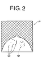
- Fig. 2 is a drawing of the image P' represented by the subject image data P.
- a plurality of microcalcification shadows Q 1 , noise, linear components Q 2 , and the like appear within the image.
- the anomalous shadow detection apparatus according to the current embodiment is an anomalous shadow detection apparatus for detecting the microcalcifications Q 1 within the image.
- Figs. 3A and 3B are graphs showing the two matched filters used by the microcalcifications enhanced image obtaining means 20. These graphs of the two matched filters show the form of the microcalcification shadows and the concentration curve, respectively, and the same graphs also show the relationship between the concentration ratio "highest concentration value/microcalcifications shadows concentration value" obtained for the main and sub-scanning directions at each pixel position.
- the first matched filter shown in Fig. 3A (hereinafter referred to as matched filter A) is a matched filter configured so as to conform to the shape, etc., of a typical unclear microcalcification shadow; wherein the concentration ratio at the center point of the microcalcification shadow is comparatively small (approximately 0.2 in the graph), and is formed having a broad base field (approximately 5 x 5 pixels in the graph) .
- matched filter B is a matched filter configured so as to conform to the shape, etc., of a typical microcalcification shadow; wherein the concentration ratio at the center point of the microcalcification shadow is comparatively large (approximately 0.55 in the graph), and is formed having a narrow base field (approximately 2 x 2 pixels in the graph).
- the microcalcifications enhanced image obtaining means 20 forms microcalcifications enhanced image data representing a microcalcifications enhanced image in which the microcalcification shadows having the same characteristics as each of the matched filters are enhanced and highlighted within the image.
- filter parameters can be set so that the concentration of the shadow portions (that is, the suspected microcalcification portions) having the degree of concentration distribution shown in each of the graphs 3a and 3b is relatively enhanced.
- a two dimensional filter indicated in Chart 1 may be utilized for Figure 3A
- a two dimensional figure indicated in Chart 2 may be utilized for Figure 3B, for example.
- Chart 1 0.01 0.06 0.08 0.06 0.01 0.04 0.12 0.17 0.12 0.04 0.07 0.15 0.22 0.15 0.07 0.04 0.12 0.17 0.12 0.04 0.01 0.06 0.08 0.06 0.01 Chart 2 0.00 0.00 0.07 0.00 0.00 0.07 0.13 0.07 0.00 0.07 0.13 0.60 0.13 0.07 0.00 0.07 0.13 0.07 0.00 0.00 0.07 0.00 0.00 0.00 0.00 0.00 0.00 0.00 0.00
- the detecting means 30 utilizes the detection threshold values, which have been specifically set for each set of image data, to perform the detection process on the three sets of image data inputted thereto. Note that the detection threshold value for each specific image data have been set at the detecting means 30 in advance.
- Fig. 4 is a flowchart of the steps of the anomalous shadow detection process according to the anomalous shadow detection apparatus of the current embodiment.
- the ultrafine structures image obtaining means 10 forms, by use of a morphology filtering process, an ultrafine structures image (step S10).
- the thus formed ultrafine structures image is an image formed in the course of performing, utilizing a morphology computation, a microcalcification shadows detection process (a morphology filtering process).
- a morphology filtering process a microcalcification shadows detection process
- a morphology computation process o generally consists of a series of set operations in an N-dimensional space. However, the process explained hereunder is directed to a two-dimensional monotone image for the sake of simplicity.
- the two-dimensional monotone image is regarded as a three-dimensional space constituted of a certain number of coordinate points, (x, y), having respective heights corresponding to an image concentration value f(x, y) thereof.
- high brightness high signal level signals are to be used, wherein the image signals are of a greater value as the concentrations thereof are lower (having higher brightness when displayed on a CRT screen).
- the dilation operation is an operation of searching for the maximum value within a width range of ⁇ m (a value determined by structural element B), centered on a pixel of interest (see Figure 5A).
- the erosion operation is an operation of searching for the minimum value within a width range of ⁇ m centered on a pixel of interest (see Fig. 5B).
- the opening operation smoothes the image concentration distribution on the low-brightness side thereof to filter out up-pointing peaks, (i.e., those parts with higher brightness and thus lower image concentration than adjacent areas thereof) which occur within a range spatially narrower than the present example (see Fig. 5C).
- the mask size is 2m in the present example.
- the closing operation smoothes the image concentration distribution on the high-brightness side thereof to filter out down-pointing peaks (i.e., those parts with lower brightness and thus higher image concentration than adjacent areas thereof) which occur within a range spatially narrower than a mask size of 2m (see Fig. 5D).
- the dilation operation would be the operation identical to the above-described erosion operation (see Fig. 5B) and the erosion operation wouldbe the operation identical to the above-described dilation operation (see Fig. 5A).
- the opening operation wouldbe the operation identical to the above-described closing operation (see Fig. 5D) and the closing operation would be the same operation identical to the above-described opening operation (see Fig. 5C).
- the image concentration signal f(x, y) of higher level is assumed to represent higher brightness.
- an elongated normal shadow which usually has a dimension longer than that of structuring element B in one or more directions corresponding to directions of Bi, still remains after the opening operation (i.e., the operation represented by the second term of the equation (7)). Accordingly, an image containing only those shadows strongly suspected to be calcification shadows will be derived by subtracting the smoothed image, which is obtained through the opening operation and contains no ultrafine structures, from an original image f.
- the images obtained according to the formula (7) or (8) that is to say, the image data representing a smoothed image obtained by eliminating the ultrafine structures from the original image, and the image data representing the differential image of the original image are ultrafine structures image data P s .
- the ultrafine structures image data P s is inputted to the microcalcifications enhanced image obtaining means 20.
- the microcalcifications enhanced image obtaining means 20 forms respective microcalcifications enhanced images P a , P b (steps S21, S22).
- Figs. 7A, 7B and 7C are graphs illustrating the operation of enhancing, by use of matched filters, the specified signal portions (shadows having the same characteristics as the respective matched filter) within a ultrafine structures image to obtain a microcalcifications enhanced image data (enhancement processed image data).
- step S21 wherein the unclear microcalcification shadows within the image represented by the ultrafine structures image data P s are enhanced and highlighted to obtain a microcalcifications enhanced image data P a .
- the matched filter B shown in Fig. 3B is used in step S22, wherein the typical microcalcification shadows within the image represented by the ultrafine structures image data P s are enhanced and highlighted to obtain a microcalcifications enhanced image data P b .
- ultrafine structures image data P s is inputted to the detecting means 30 from the ultrafine structures image obtaining means 10 and the microcalcifications enhanced image data P a , P b are inputted to the detecting means 30 from the microcalcifications enhanced image obtaining means 20; the detecting means 30 then performs the respective particular microcalcification shadow detection processes on each inputted image data (steps S31, S32, S33).
- step S33 using the ultrafine portion data based on the morphology computation of the formula (9) shown below, the shadows not cast by microcalcifications (normal shadows) are eliminated from the ultrafine structures image data P s (P of formula (7)).
- M grad (1/2) ⁇ ⁇ f ⁇ B-f ⁇ B ⁇
- T1 and T2 represent empirically determined preset threshold values.
- step S31 the normal shadows included in the microcalcifications enhanced image data P a can be eliminated therefrom by use of formula (9), and utilizing the threshold values A1, A2, suspected calcifications image data C a can be obtained by the formula (10); and in step S32 the normal shadows included in the microcalcifications enhanced image data P b can be eliminated therefrom by use of formula (9), and by utilizing the threshold values B1, B2, suspected calcifications image data C b can be obtained by the formula (10).
- the threshold value setting method based on the readout sensitivity (an S value) and the latitude (an L value) of the subject image data P, proposed in Japanese Unexamined Patent Publication No. 8(1996)-263648 is employed. That is to say, the subject image data obtained by the CR system is a signal value obtained by adjusting the readout conditions (S value, L value) by way of the EDR; the radiation quantum noise contained in the radiation image is included in this signal value.
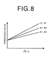
- Fig. 8 is a graph illustrating the relationship between the readout conditions (S value, L value) and each threshold value.
- each of the threshold values is set as a proportionately large value corresponding to the highness of the readout sensitivity value, and/or the smallness of the latitude.
- the threshold value for the microcalcifications enhanced image data P a is a smaller value than the other threshold values. That is to say, the threshold values for the microcalcifications enhanced image data P a , P b , which have been obtained using the matched filters A, B, are set, based on the characteristics of said respective matched filters, as shown in Fig. 8.
- step S34 the sum of the three suspected calcifications image data C a , C b , and C s obtained in steps S31, S32 and S33 is calculated, and a calcifications image data C representing the microcalcification shadows detection results.
- a microcalcifications enhanced image data is formedutilizing amatched filter 8 modeled on the characteristics such as the form and the like of an unclear microcalcification shadow and a matched filter B modeled on the characteristics such as the form and the like of a typical microcalcification shadow, two types of microcalcification shadows are enhanced and highlighted, it becomes possible to relatively suppress other shadows such as noise, linear structures and the like, whereby the detection accuracy can be improved.
- the anomalous shadow detection apparatus achieves an performance improvement in anomalous shadow detection processing by rendering it possible to accurately detect such unclear microcalcification shadows.
- the threshold value is set for each image data, because the threshold value is optimized, based on the readout conditions of the subject image data and the characteristics of the matched filter applied thereto, for every image data, it becomes possible to set the threshold value at an appropriate level matched to the quantity of noise present in each image data, leading to an improvement in detection performance.
- threshold values T1, T2, A1, A2, B1, B2 have been set in advance at the detecting means 30, a threshold setting means for setting each threshold value can be provided; wherein the readout conditions (S value, L value) of the subject image data and the characteristics of the matched filters A, B can be inputted to the threshold value setting means, and the threshold value setting means can automatically set, based on the inputted readout conditions (S value, L value) of the subject image data and the characteristics of the matched filters A, B, at the detecting means 30.
- each suspected calcifications image data can be a detection results image data
- the detection results image data can be an image data formed of only the microcalcification shadows representing a higher malignancy, which have been extracted from each suspected calcifications image data.
- the anomalous shadows detection apparatus is not limited thereto; an embodiment wherein the ultrafine structures image data is not used, and two or more types of microcalcification enhanced image data are used to obtain two or more suspected calcifications image data, for example, is also possible.
- the present invention is not limited to being used for mammography CAD applications; the present invention can be applied to chest CAD and the like, and various types of subjects of imaging.
Landscapes
- Engineering & Computer Science (AREA)
- Quality & Reliability (AREA)
- Physics & Mathematics (AREA)
- Medical Informatics (AREA)
- Nuclear Medicine, Radiotherapy & Molecular Imaging (AREA)
- Radiology & Medical Imaging (AREA)
- Health & Medical Sciences (AREA)
- Computer Vision & Pattern Recognition (AREA)
- General Health & Medical Sciences (AREA)
- General Physics & Mathematics (AREA)
- Theoretical Computer Science (AREA)
- Image Processing (AREA)
- Apparatus For Radiation Diagnosis (AREA)
- Image Analysis (AREA)
- Radiography Using Non-Light Waves (AREA)
Abstract
Description
| | ||||
| 0.01 | 0.06 | 0.08 | 0.06 | 0.01 |
| 0.04 | 0.12 | 0.17 | 0.12 | 0.04 |
| 0.07 | 0.15 | 0.22 | 0.15 | 0.07 |
| 0.04 | 0.12 | 0.17 | 0.12 | 0.04 |
| 0.01 | 0.06 | 0.08 | 0.06 | 0.01 |
| | ||||
| 0.00 | 0.00 | 0.07 | 0.00 | 0.00 |
| 0.00 | 0.07 | 0.13 | 0.07 | 0.00 |
| 0.07 | 0.13 | 0.60 | 0.13 | 0.07 |
| 0.00 | 0.07 | 0.13 | 0.07 | 0.00 |
| 0.00 | 0.00 | 0.07 | 0.00 | 0.00 |


Claims (5)
- An anomalous shadow detection apparatus for detecting, based on the image data representing a subject image, the microcalcification shadows within said subject image, comprising:an ultrafine structures image obtaining means for obtaining an ultrafine structures image representing the ultrafine structures appearing in a subject image,a microcalcifications enhanced image obtaining means for subjecting said ultrafine structures image to an image process employing a plurality of form dependent filters corresponding to the forms of a the of microcalcifications to obtain a plurality of microcalcification enhanced images, anda detecting means for detecting, based on the microcalcification enhanced image data representing said obtained plurality of microcalcification enhanced images, the microcalcifications shadows.
- An anomalous shadow detection apparatus as defined in claim 1, wherein
said detecting means is a means for detecting, by use of a predetermined detection threshold value set for each of the plurality of microcalcification enhanced images, the microcalcifications shadows. - An anomalous shadow detection apparatus for detecting, based on the image data representing a subject image, the microcalcification shadows within said subject image,
an ultrafine structures image obtaining means for obtaining an ultrafine structures image representing the ultrafine structures appearing in a subject image, a microcalcifications enhanced image obtaining means for subjecting said ultrafine structures image to an image process employing at least one form dependent filter corresponding to the form of the microcalcifications shadows to obtain at least one microcalcification enhanced image, and
a detecting means for detecting, based on the ultrafine structures image data representing the obtained ultrafine structures image and the microcalcification enhanced image data representing the obtained microcalcification enhanced image, the microcalcifications shadows. - An anomalous shadow detection apparatus as defined in claim 3, wherein
said detecting means is a means for detecting, by use of a predetermined detection threshold value set for each of the ultrafine structures images and the microcalcification enhanced images, microcalcifications shadows. - An anomalous shadow detection apparatus as defined in any of claims 2, 3, or 4, wherein
the predetermined detection threshold value set for the microcalcifications enhanced image is set based on the characteristics of the form dependent filter employed when said microcalcifications enhanced image was obtained.
Applications Claiming Priority (2)
| Application Number | Priority Date | Filing Date | Title |
|---|---|---|---|
| JP2001249199A JP2003057771A (en) | 2001-08-20 | 2001-08-20 | Abnormal shadow detector |
| JP2001249199 | 2001-08-20 |
Publications (2)
| Publication Number | Publication Date |
|---|---|
| EP1288861A2 true EP1288861A2 (en) | 2003-03-05 |
| EP1288861A3 EP1288861A3 (en) | 2007-12-12 |
Family
ID=19078241
Family Applications (1)
| Application Number | Title | Priority Date | Filing Date |
|---|---|---|---|
| EP02018184A Withdrawn EP1288861A3 (en) | 2001-08-20 | 2002-08-19 | Detection of anomalous shadow in digital image |
Country Status (3)
| Country | Link |
|---|---|
| US (1) | US20030039385A1 (en) |
| EP (1) | EP1288861A3 (en) |
| JP (1) | JP2003057771A (en) |
Families Citing this family (1)
| Publication number | Priority date | Publication date | Assignee | Title |
|---|---|---|---|---|
| JP4631260B2 (en) * | 2003-09-29 | 2011-02-16 | コニカミノルタエムジー株式会社 | Image diagnosis support apparatus, image diagnosis support method, and program |
Family Cites Families (17)
| Publication number | Priority date | Publication date | Assignee | Title |
|---|---|---|---|---|
| US4907156A (en) * | 1987-06-30 | 1990-03-06 | University Of Chicago | Method and system for enhancement and detection of abnormal anatomic regions in a digital image |
| US5046147A (en) * | 1988-10-17 | 1991-09-03 | Fuji Photo Film Co., Ltd. | Radiation image processing method |
| JPH07299053A (en) * | 1994-04-29 | 1995-11-14 | Arch Dev Corp | Computer diagnosis support method |
| US5825936A (en) * | 1994-09-22 | 1998-10-20 | University Of South Florida | Image analyzing device using adaptive criteria |
| DE69629732T2 (en) * | 1995-01-23 | 2004-07-15 | Fuji Photo Film Co., Ltd., Minami-Ashigara | Device for computer-aided diagnosis |
| EP0813720A4 (en) * | 1995-03-03 | 1998-07-01 | Arch Dev Corp | METHOD AND SYSTEM FOR DETECTING LESIONS IN MEDICAL IMAGES |
| JP3597272B2 (en) * | 1995-10-12 | 2004-12-02 | 富士写真フイルム株式会社 | Abnormal shadow candidate detection method |
| US6246782B1 (en) * | 1997-06-06 | 2001-06-12 | Lockheed Martin Corporation | System for automated detection of cancerous masses in mammograms |
| US6620382B1 (en) * | 1998-05-22 | 2003-09-16 | Biopheresis Technologies, Llc. | Method and compositions for treatment of cancers |
| ATE540686T1 (en) * | 1999-05-12 | 2012-01-15 | Uab Research Foundation | ADENOVIRUS WITH INCREASED INFECTIOUSITY AND CONDITIONAL REPLICATION CAPACITY AND THEIR USES |
| US6254614B1 (en) * | 1999-10-18 | 2001-07-03 | Jerry M. Jesseph | Device and method for improved diagnosis and treatment of cancer |
| US6900239B2 (en) * | 2000-02-29 | 2005-05-31 | Ilwz Ilex Products, Inc. | Tumor chemopotentiation using isocoumarin derivatives |
| US6589981B2 (en) * | 2000-02-29 | 2003-07-08 | Ilex Oncology, Inc. | Tumor radiosensitization and/or chemopotentiation using isocoumarin derivatives |
| US20020051515A1 (en) * | 2000-06-06 | 2002-05-02 | Fuji Photo Film Co., Ltd. | Method of and system for detecting prospective abnormal shadow |
| JP2002099896A (en) * | 2000-09-22 | 2002-04-05 | Fuji Photo Film Co Ltd | Abnormal shadow candidate detecting method and apparatus |
| CA2349506C (en) * | 2001-06-14 | 2009-12-08 | Duke University | A method for selective expression of therapeutic genes by hyperthermia |
| US6859522B2 (en) * | 2002-09-13 | 2005-02-22 | University Of Rochester Medical Center | Carotid artery filter system for single view dental panoramic radiographs |
-
2001
- 2001-08-20 JP JP2001249199A patent/JP2003057771A/en active Pending
-
2002
- 2002-08-19 EP EP02018184A patent/EP1288861A3/en not_active Withdrawn
- 2002-08-20 US US10/223,440 patent/US20030039385A1/en not_active Abandoned
Also Published As
| Publication number | Publication date |
|---|---|
| US20030039385A1 (en) | 2003-02-27 |
| EP1288861A3 (en) | 2007-12-12 |
| JP2003057771A (en) | 2003-02-26 |
Similar Documents
| Publication | Publication Date | Title |
|---|---|---|
| AU706993B2 (en) | Computerized detection of masses and parenchymal distortions | |
| JP4718003B2 (en) | Method for detecting interval changes in radiographs | |
| US7916912B2 (en) | Efficient border extraction of image feature | |
| US7391895B2 (en) | Method of segmenting a radiographic image into diagnostically relevant and diagnostically irrelevant regions | |
| US7359542B2 (en) | Method and apparatus for detecting anomalous shadows | |
| US20110229006A1 (en) | Method, apparatus, and program for detecting abnormal patterns | |
| US7242794B2 (en) | Method and apparatus for detecting abnormal pattern candidates | |
| JPH0737074A (en) | Method and apparatus for detecting changes over time between consecutive chest images | |
| US7912263B2 (en) | Method for detecting clipped anatomy in medical images | |
| JP2001346786A (en) | Questionable image detecting method, reproducing method, and detecting system | |
| US7027631B2 (en) | Method and system for detecting suspected anomalous shadows | |
| US6356652B1 (en) | Visualization of diagnostically irrelevant zones in a radiographic image | |
| JP2005198798A (en) | Radiation image processing apparatus and processing method | |
| US7155041B2 (en) | Anomalous shadow detection system | |
| JP2001076141A (en) | Image recognizing method and image processor | |
| JPH10108073A (en) | Method and device for processing bone part image | |
| JP2004283281A (en) | Image processing apparatus and image processing method | |
| JPH09106448A (en) | Detecting method for abnormal shadow candidate | |
| US20050161617A1 (en) | Image processing method, apparatus, and program | |
| EP1288861A2 (en) | Detection of anomalous shadow in digital image | |
| US20050243334A1 (en) | Image processing method, image processing apparatus and image processing program | |
| JP4169954B2 (en) | Abnormal shadow candidate detection method | |
| JP4765391B2 (en) | Image processing method, image processing apparatus, and image processing program | |
| US20020051515A1 (en) | Method of and system for detecting prospective abnormal shadow | |
| JP2006239270A (en) | Abnormal shadow detector, abnormal shadow detection method, and its program |
Legal Events
| Date | Code | Title | Description |
|---|---|---|---|
| PUAI | Public reference made under article 153(3) epc to a published international application that has entered the european phase |
Free format text: ORIGINAL CODE: 0009012 |
|
| AK | Designated contracting states |
Kind code of ref document: A2 Designated state(s): AT BE BG CH CY CZ DE DK EE ES FI FR GB GR IE IT LI LU MC NL PT SE SK TR Designated state(s): AT BE BG CH CY CZ DE DK EE ES FI FR GB GR IE IT LI LU MC NL PT SE SK TR |
|
| AX | Request for extension of the european patent |
Extension state: AL LT LV MK RO SI |
|
| RAP1 | Party data changed (applicant data changed or rights of an application transferred) |
Owner name: FUJIFILM CORPORATION |
|
| PUAL | Search report despatched |
Free format text: ORIGINAL CODE: 0009013 |
|
| AK | Designated contracting states |
Kind code of ref document: A3 Designated state(s): AT BE BG CH CY CZ DE DK EE ES FI FR GB GR IE IT LI LU MC NL PT SE SK TR |
|
| AX | Request for extension of the european patent |
Extension state: AL LT LV MK RO SI |
|
| 17P | Request for examination filed |
Effective date: 20080326 |
|
| AKX | Designation fees paid |
Designated state(s): BE DE FR NL |
|
| 17Q | First examination report despatched |
Effective date: 20090319 |
|
| STAA | Information on the status of an ep patent application or granted ep patent |
Free format text: STATUS: THE APPLICATION IS DEEMED TO BE WITHDRAWN |
|
| 18D | Application deemed to be withdrawn |
Effective date: 20090730 |