EP1288748A2 - Controller and operating system - Google Patents
Controller and operating system Download PDFInfo
- Publication number
- EP1288748A2 EP1288748A2 EP02008241A EP02008241A EP1288748A2 EP 1288748 A2 EP1288748 A2 EP 1288748A2 EP 02008241 A EP02008241 A EP 02008241A EP 02008241 A EP02008241 A EP 02008241A EP 1288748 A2 EP1288748 A2 EP 1288748A2
- Authority
- EP
- European Patent Office
- Prior art keywords
- task
- tasks
- execution
- task group
- group
- Prior art date
- Legal status (The legal status is an assumption and is not a legal conclusion. Google has not performed a legal analysis and makes no representation as to the accuracy of the status listed.)
- Granted
Links
Images












Classifications
-
- G—PHYSICS
- G05—CONTROLLING; REGULATING
- G05B—CONTROL OR REGULATING SYSTEMS IN GENERAL; FUNCTIONAL ELEMENTS OF SUCH SYSTEMS; MONITORING OR TESTING ARRANGEMENTS FOR SUCH SYSTEMS OR ELEMENTS
- G05B19/00—Program-control systems
- G05B19/02—Program-control systems electric
- G05B19/04—Program control other than numerical control, i.e. in sequence controllers or logic controllers
- G05B19/042—Program control other than numerical control, i.e. in sequence controllers or logic controllers using digital processors
Definitions
- the present invention relates to a programmable logic controller (PLC) for monitoring and controlling a device and a robot of a production line in industrial application, or a controller for monitoring and controlling various devices including an air conditioner, a security equipment, an illuminator, an elevator and the like installed in a building or at home, or devices including power, gas and water supply systems and the like for supporting an infrastructure. More particularly, the invention relates to a network controller connected to a network to perform communications with an external device, which necessitates both network communication processing and real-time control processing.
- PLC programmable logic controller
- Controllers equipped with network communication functions are installed in various types of equipments and devices, and adapted to perform communications between a host and a terminal or a controller, alternatively between the controllers.
- priority assignment is first carried out in a fixed manner among operations (tasks) including control processing, network communication processing and the like, and then these tasks are executed and managed by using priority scheduling of a real-time OS.
- operations including control processing, network communication processing and the like
- priority scheduling of a real-time OS available in the conventional art, " ⁇ ITRON 4.0 Specifications" Chap. 3.2 (ITRON Division of TRON Association, edited by Hiroaki Takada under monitoring of Ken Sakamura) can be cited.
- JP-A-11-191002 (1999) guarantees real-time execution of an important task by dynamically changing priority of tasks for controlling a device according to an operating state of the device, to which a controller is connected.
- JP-A-11-191002 (1999) employs a configuration, where priority of tasks for controlling the device according to the operating state of the device, to which the controller is connected, is dynamically changed, different from the fixed priority scheduling.
- priority of tasks for controlling the device according to the operating state of the device, to which the controller is connected is dynamically changed, different from the fixed priority scheduling.
- objects of the present invention are to provide a controller capable of guaranteeing both real-time execution of control processing and throughput of network communication processing by one information processing means, and an operating system.
- a controller which is provided with a plurality of tasks, and a program including an operating system for controlling the execution of the tasks, wherein the plurality of tasks are managed by being classified into a communication task group for performing communications with a network communication system and a control task group for monitorially controlling a target to be monitorially controlled; an execution order of the plurality of tasks are switched by a group unit; and in accordance with the switched task group, information obtained from the target to be monitorially controlled or the network communication system is processed.
- a controller of the present invention comprises a memory for storing a plurality of tasks and a program including an operating system for controlling the execution of the tasks; an I/O interface for transferring information with a target to be monitorially controlled; a network control circuit for transferring information with a network communication system; a microprocessor for processing either of the information in accordance with the program stored in the memory; and task switching means for managing the plurality of tasks stored in the memory by classifying them into a communication task group for performing network communications and a control task group for monitorially controlling the target to be monitorially controlled, and for switching an execution order of the plurality of tasks by a group unit.
- the task switching means can have a function of managing the plurality of tasks by classifying them into the communication task group, the control task group, and a management task group for management including the internal monitoring of the microprocessor, and a function of switching the execution order of the plurality of tasks by a group unit.
- a controller comprising the following elements as software: a plurality of tasks for performing communications and control; and task switching means for managing the plurality of tasks by classifying them into a communication task group for communicating with a network communication system, and a control task group for monitorially controlling a target to be monitorially controlled, and switching an execution order of the plurality of tasks by a group unit.
- the controller thus constructed, as the plurality of tasks, ones for communications, control and management can be used ands, as the task switching means, one having a function of managing the plurality of tasks by classifying them into a communication task group, a control task group, and a management task group for management, and switching an execution order of the plurality of tasks by a group unit can be used.
- an operating system comprising a system call for managing a plurality of tasks by classifying them into a plurality of groups and by a group unit, and switching an execution order of the plurality of tasks by the group unit.
- a remote monitorial control system comprising one of the above-described controllers, and an information terminal connected to the above-described network communication system.
- a distributed control system comprising a plurality of any of the above-described controllers.
- the controllers are disposed in a distributed manner.
- FIG. 1 is a block diagram showing a basic configuration of a controller.
- the controller 1 comprises a memory 17, a CPU 100, a network control circuit 11, an I/O interface 10, and a bus 181.
- the memory 17, the network control circuit 11, and the I/O interface 10 are interconnected through the bus 181.
- the network control circuit 11 is connected to a LAN 40 constituting a network communication system, and adapted to transfer communication information with the LAN 40.
- the I/O interface 10 is connected to devices 301,..., 30n (n is an integer) as targets to be monitorially controlled, and adapted to transfer information regarding control information with each device.
- the CPU 100 includes a timer 16021, and an interruption control circuit (INT) 16020, which constitute an information processing system.
- the CPU 100 is provided as information processing means for processing information obtained from the LAN 40, and information obtained from each of the devices 301 to 30n.
- the memory 17 includes a communication task group 13, a control task group 141, a management task group 142, task group execution mode switching 15, and a real-time operating system 16.
- the communication task group 13 includes two communication tasks 51 and 52; the control task group 141 two control tasks 53 and 54; and the management task group 142 three control tasks 55, 56 and 57.
- the real-time operating system 16 includes a network driver 172.
- the task group execution mode switching 15 is provided as task switching means for managing a plurality of tasks by classifying them into the communication task group 13 for communicating with the LAN 40, the control task group 141 for monitorially controlling the devices 301 to 30n, and the management task group 142 for management including internal monitoring of the CPU 100, and switching an execution order of the plurality of tasks.
- programs executed by the CPU 100 and a region for storing data necessary for execution of the programs are present.
- the programs executed by the CPU 100 are those for the communication task group 13, the control task group 141, the management task group 142, the task group execution mode switching 15, and the real-time operating system 16.
- an object is to execute both control processing and network communication processing in coexistence on one microprocessor and, basically, the number of microprocessors (CPU) on the controller is one.
- a network of an information system such as Ethernet, HomePNA, IEEE1394, IEEE802.11, or HomePLUG.
- the invention can be applied to networks other than those of the information system, e.g., a field network such as Profibus or ControlNet, or a network of a control system such as ARCNET.
- the LAN 40 includes a LAN cable (a private line, a telephone line, an electric lamp line or the like) defined by the above-described network, or radio.
- a basic operation of the controller 1 is as follows.
- the CPU 100 executes the tasks from one in an executable state and high in priority in order by a task scheduling function of the real-time operating system 16. If a task to be executed belongs to the communication task group, when information of this task is transferred through the network driver 172 to the CPU 100, the CPU 100 reads data received by the network control circuit 11 from the LAN 40, then executes corresponding communication processing, or sends transmission data to the network control circuit 11, and sends the transmission data from the network control circuit 11 to the LAN 40.
- a task to be executed belongs to the control task group, when information of this task is transferred through the I/O interface 11 to the CPU 100, the CPU 100 receives data from the external devices 301 to 30n, executes corresponding control processing, and then monitorially controls the devices by outputting a result of the execution through the I/O interface 11 to the external devices 301 to 30n. If a task to be executed belongs to the management task group, when information of this task is transferred to the CPU 100, the CPU 100 monitors the inside of the controller, obtains log information or executes dedicated port communication processing for debugging.
- priority of tasks in the task group is changed in block by the task group execution mode switching 15 periodically actuated by the timer 16021 based on an interruption (switching command) 16020, the tasks in the group are suspended (Suspend) in block, or processing is resumed (Resume).
- execution of the tasks is controlled by a group unit. Accordingly, for each mode switching, tasks to be executed, or an execution order of tasks is varied.
- FIG. 2 shows a basic configuration of the invention including a first embodiment of the task group execution mode switching 15.
- component other than internal components of the task group execution mode switching 15 are similar to those of FIG. 1.
- the task group execution mode switching 15 includes an execution mode 151, an execution counter 152, task group priority changing 153,and task group information 154.
- the task execution mode switching 15 includes interruption processing or a task. In the latter case, the task execution mode switching 15 is switched following execution of the task, and priority of the task execution mode switching 15 is set highest, or at least higher than priority of any tasks constituting the task group as a target to be monitorially controlled.
- FIG. 3 shows an example of management by the execution mode, where deviation of priority among the tasks during mode switching is shown.
- a mode 0 a mode 1
- a mode 2 a mode 2
- the modes are cyclically switched as follows: Mode 0 ⁇ mode 1 ⁇ mode 2 ⁇ mode 0 ⁇ ⁇
- priority of deviation is added to all the tasks in each task group.
- Duration of each mode is set in the execution counter 152.
- the timer 16021 of FIG. 1 measures time, and actuates the task execution mode switching 15 by generation of interruption (switching command) after passage of the set duration.
- FIG. 4 shows set values of mode duration in the execution counter, in a case where the above-described three modes are present.
- the mode 0 is set to 3 milli-sec.; the mode 1 to 3 milli-sec.; and the mode 2 to 4 milli-sec.; and one cycle to 10 milli-sec.
- the task group information 154 is used for managing registered tasks of each task group. As shown in FIG. 5, the task group information 154 may be formed by using a structure or an array. In FIG. 5, for each task group, the number of tasks registered in the task group, information of each registered task (task ID, or a pointer to the task control table managed by the real-time operating system 16 for task scheduling, are registered.
- the task group information 154 As another structure of the task group information 154, as shown in FIG. 6, a method of constructing it in a list by using pointers to connect the task control table.
- the task group information includes a communication task group 130, a control task group 1410, and a management task group 1420.
- the communication task group 130 is connected through the pointers to task control tables 510 and 520; the control task group 1410 through the pointers to task control tables 530 and 540; and the management task group 1410 through the pointers to task control tables 550, 560 and 570.
- the task control tables 510 to 570 respectively have task priority information 511, 521, 531, 541, 551, 561 and 571. To construct such a list, new linkage information (a pointer to a next task control table, or a pointer to a previous task control table) must be provided in the task control table.
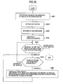
- interruption occurs form the timer, and the task execution mode switching 15 is actuated (9081).
- the task group priority changing 153 first updates an execution mode (9082). The updating of the execution mode is achieved by calculation described below.
- New execution mode number previous execution mode (number of all (number+1)% modes)
- duration of the new execution mode is set in the execution counter (9083).
- task priority is updated (9086). The updating is achieved by calculation below.
- Priority of task of current execution mode priority of previous execution mode+priority deviation during switching to current mode of task group to which it belongs (priority deviation of task group during mode switching (see FIG. 3))
- FIG. 8 shows initial priority of each of totally seven tasks 1 to 7 of FIG. 1.
- a smaller value means higher priority.
- the task group execution mode switching 15 is operated to add priority of priority deviation of FIG. 3 to these tasks during mode switching. As a result, priority of the task on each mode becomes similar to that shown in FIG. 9.
- priority deviation during switching of last mode ⁇ first mode i.e., mode 2 ⁇ mode 0 of FIG. 3 is used.
- initial priority 3 is added to priority deviation 18 of mode 2 ⁇ mode 0 to make 21.
- Priority on the mode 2 is set a value equal to that of initial priority shown in FIG. 8.
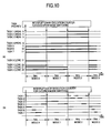
- FIG. 10(a) is a graph showing FIG. 9 by a time chart. For example, on the mode 0, since priorities of the tasks are respectively set to 9, 10, 11, 17, 20, 21 and 22, interruptions occur in the tasks 5, 6, 7, 3, 4, 1 and 2 from high in priority order.
- FIG. 10(b) is a graph showing a time chart of an execution example of each task. As shown in the graph of FIG. 10(b), in a time zone of the mode 0, the management task group is preferentially executed; on the mode 1, the control task group; and on the mode 2, the communication task group.
- the plurality of tasks are managed by the group unit, and the execution order of the plurality of tasks is switched by the group unit.
- processing of information of each group can be surely guaranteed.
- the execution order of the plurality of tasks is switched by the group unit, the execution order of each task is changed in accordance with priority. Thus, it is possible to guarantee minimum execution time for the control processing and the communication processing.
- FIG. 11 shows the second embodiment of the task group execution mode switching 15.
- the task group execution mode switching 15 includes an execution mode 151, an execution counter 152, a task group suspension/resumption processing 1531, and task group information 154. That is, the second embodiment is different from the first embodiment of the task group execution mode switching 15 of FIG. 2 in that the task group priority changing 153 is replaced by the task group suspension/resumption processing 1531.
- the other components 151, 152 and 154 are similar to those of the first embodiment.
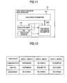
- FIG. 12 shows an example of management by the execution mode, specifically a change in an execution state of the task group during mode switching.
- a mode 0 a mode 1
- a mode 2 a mode 2
- the modes are switched cyclically as follows, Mode 0 ⁇ mode 1 ⁇ mode 2 ⁇ mode 0 ⁇
- an execution mode of each task group is changed as follows during mode switching:
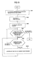
- the task group suspension/resumption processing 1531 first updates an execution mode (9082).
- duration of a new execution mode is set in the execution counter (9083).
- one task group to be edited is taken out by referring to the task group information 154 (9084). Further, for all the tasks registered in the task group (9085), the execution states of the tasks are updated by referring to changes in the execution states of the task group during mode switching (FIG. 12) (90861). The foregoing is carried out for all the tasks of all the tasks registered in the task group information 154.
- FIG. 14 shows an execution state of a task on each mode, as a result of changes made in the execution states of the totally seven tasks 1 to 7 of FIG. 1 by the operation of the task group execution mode switching 15 during mode switching of FIG. 12.
- suspension means one of forcible standby states (SUSPENDED or WAITING-SUSPENDED). This is equivalent to, when a need arises to suspend a task because of mode switching, any one of the following states, in which the task has been, i.e., an execution state (RUNNING), an executable state (READY) and a standby state (WAITING). Conversely, execution means a return of a task state to one selected from RUNNING, READY and WAITING. In a dormant state of a task (DORMANT), no state changes are made irrespective of task suspension/execution.
- DORMANT dormant state of a task
- Execution states of the task groups on respective modes are as follows:
- FIG. 15 is a graph showing a time chart of an execution example of each task of FIG. 14. As shown in the graph of FIG. 15, after an occurrence of interruption during execution mode switching by the execution counter, at time of mode starting, the task group execution mode switching 15 is executed, and changes are made in execution states of the tasks. In a time zone of the mode 0, since the control task group and the communication task group are both suspended, only the management task group is executed. On the mode 1, execution of the control task group is resumed, and execution is made preferentially from the management task group. On the mode 2, execution of the communication task group is resumed, and this group is preferentially executed before the other task groups. A difference from the graph of FIG.
- An advantage of the second embodiment of the task group execution mode switching 15 is basically similar to that of the first embodiment. A difference is that since the CPU becomes idle more frequency than in the first embodiment, and processing time is shorter for the task suspension/resumption than for the changing of the priority of the tasks of the first embodiment during mode switching, overhead is smaller than that of the first embodiment during mode switching.
- WEB communications using HTTP protocol represented by WWW or communications of TCP/IP base standard in the network communications of an information system, such as TELNET or FTP communications, or communications using a socket are assumed.
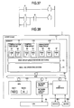
- sequence control requiring real-time processing is assumed, which is described in a ladder language general used as a descriptive language for a programmable logic controller (PLC), an ladder diagram (LD) language internationally standardized as IEC61131-3, an instruction list (IL) language, a structured text (ST) language, a function block diagram (FBD) language, a sequential function chart (SFC), a flowchart or the like.
- FIG. 37 shows an example of sequence control described in the ladder language.
- A, C, D and F are equivalent to contacts (inputs), and B and E to contacts (outputs). These contacts take digital values of 0 or 1.
- the number of task groups, and the number of tasks of the task group described above are just examples, and the number of task groups may be other than three. That is, needless to say, the foregoing embodiment can be applied even if the number is task groups is one, two or four or more. Similarly, the number of tasks constituting each task group can be optionally set to one or more.
- the embodiment has been described by way of example, where there are three types of execution modes, and duration of the modes were respectively 3 milli-sec., 3 milli-sec., and 4 milli-sec., i.e., one cycle of 10 milli-sec. Needless to say, however, the embodiment can be applied even if the number of mode types may be two, four or more. In addition, duration of each mode can also be set optionally.
- the priority value set in each task, and the value of the priority deviation during mode switching described above are also just examples, and other values can be set.
- the number of network control circuits is one on the controller. In the case of two or more network control circuits, each network control circuit needs a dedicated communication task group, but the embodiment can be applied.
- the plurality of tasks are managed by the group unit, and the execution order of the plurality of tasks is switched by the group unit. Therefore, it is possible to surely guarantee processing of information of each group.
- FIG. 16 shows a configuration example of a controller of the invention, focusing on a hardware configuration.
- the controller 1 comprises a CPU 100, a memory 17, a PHY module 182, and a network interface 183.
- the memory 17, and the CPU 100 are connected to an external bus 181.
- the CPU 100 includes a CPU core 1001, a timer 16021, an interruption control circuit (INT in the drawing) 16020, an I/O interface 10, and a communication controller medium nondependent portion 110.
- the CPU core 1001, the communication controller medium non-dependent portion 110, an the I/O interface 10 are connected to an internal bus 1002.
- the PHY module 182 is a transceiver for achieving a network physical layer.
- the communication controller medium non-dependent portion 110, the PHY module 182, and the network interface 183 constitute the network control circuit shown in FIG. 1.
- the controller 1 is connected to a LAN 40 by the network interface 183, and to devices 30l to 30n (n is an integer) by the I/O interface 10, thus connected to an external device.
- An application program 171 includes a communication task group 13, a control task group 141, and a management task group 142.
- programs are present including task group execution mode switching 15, a real-time operating system 16, a task scheduler 160 included in the real-time operating system 16, an I/O driver 101, and a network driver 172.
- the network driver 172 includes transmission buffer management 1721, a transmission buffer 1722, receiving buffer management 1731, and a receiving buffer 1732.
- the transmission buffer management 1721, and the receiving buffer management 1731 manages inputting/outputting of data to/from the buffers 1722 and 1732 to be managed by FIFO policy.
- a basic operation of the controller 1 shown in FIG. 16 is as follows.
- the CPU core 1001 in the CPU 100 executes tasks in order from those in executable states and the highest in priority by using the task scheduler 160 of the real-time operating system 16.
- a task to be executed belongs to the communication task group, network transmission, network receiving, or a higher-order communication application is executed for the task.
- transmission data is registered in the transmission buffer 1722 by the transmission buffer management 1721 in the network driver 172.
- network receiving received data stored in the receiving buffer 1732 is taken out by the receiving buffer management 1731 in the network driver 172.
- Access to the transmission buffer 1722 and the receiving buffer 1732 is also carried out by the network control circuit 11 (in FIG. 16, the communication controller medium non-dependent portion 110 to be exact). That is, the transmission data stored in the receiving buffer 1722 is taken out by referring to the transmission buffer management 1721, and data is transmitted to the LAN 40. On the other hand, the data received from the LAN 40 is registered in the receiving buffer 1732 by referring to the receiving buffer management 1731.
- a task to be executed belongs to the control task group, information of this task is transferred through the I/O driver to the I/O interface 11 to the CPU 100.
- the CPU 100 receives data entered from the external devices 301 to 30n, executes corresponding control processing, then similarly outputs a result of the control processing through the I/O driver 101 to the I/O interface 11 to the external devices 301 to 30n, thus performing monitorial control of the device.
- a task to be executed belongs to the management task group, for this task, the inside of the controller is monitored, log information is obtained, or port communication processing dedicated for debugging is carried out.
- the above-described task groups are subjected to task execution control by the group unit, for example in a manner that the tasks in the task group are changed for priority en block by the task group execution mode switching 15 periodically actuated by the timer 16021 based on an interruption entry 16020, or the tasks in the task group are suspended en block (SUSPEND) or processing is resumed (RESUME). Accordingly, for each mode switching, tasks to be executed or the execution order of tasks is varied.
- FIG. 17 shows a software configuration operated on the controller of FIG. 16.
- a communication task group 13 As application programs to be executed by the CPU on the controller 1, there are a communication task group 13, a control task group 141, and a management task group 142. Execution of these task groups is controlled by the task group execution mode switching 15. Also, as basic software, there are an real-time operating system 16, a task scheduler 160 included in the real-time operating system 16, an I/O driver 101, and a network driver 172.
- the network driver 172 includes transmission buffer management 1721, a transmission buffer 1722, receiving buffer management 1731, and a receiving buffer 1732.
- the transmission buffer management 1721, and the receiving buffer management 1731 manage inputting/outputting of data to/from buffers 1722 and 1732 to be managed by FIFO policy.
- Telnet task 501, FTP task 502, PING task 503 and Httpd task 504 as higher-order applications tasks, TCP, UDP, IP, and ICMP transmission task 507 for network transmission, and TCP, UDP, IP and ICMP transmission task 508 for network receiving are registered.
- TCP, UDP, IP and ICMP transmission task 507 transmission data is registered in the transmission buffer 1722 by the transmission buffer management 1721 in the network driver 172.
- transmission data stored in the receiving buffer 1732 is taken out by the receiving buffer management 1731 in the network driver 172.
- Access to the transmission buffer 1722, and the receiving buffer 1732 is also carried out by the network control circuit 11. That is, the transmission data stored in the receiving buffer 1722 is taken out by referring to the transmission buffer management 1721, and data is transmitted to the LAN 40. On the other hand, the data received from the LAN 40 is registered in the receiving buffer 1732 by referring to the receiving buffer management 1731.
- a normal task 512 is registered, which is operated in a manner of a background job by repeating processing of a regular task 511 executed at a predetermined period.
- a monitoring task 521 for monitoring the inside of the controller, and obtaining log information, a dedicated port communication task 522 for performing dedicated port communications for debugging, and a dedicated port control task 523 for controlling a dedicated port are registered.
- the controller 1 comprises an I/O interface 10, a network control circuit 11, and a timer 1602.
- the controller 1 is connected to the LAN 40 by the network control circuit 11, and to devices 301 to 30n (n is a positive integer) by the I/O interface 10, thus connected to an external device.
- a basic operation is carried out, i.e., tasks in each task group are executed in order from those in executable states and highest in priority by the task scheduler 160 of the real-time operating system 16.
- each task group is subjected to task execution control by a group unit, in such a manner that the tasks in the task group are changed in priority en block by the task group execution mode switching 15 periodically actuated based on interruption by the timer 16021, or the tasks in the group are suspended (SUSPEND) in block, or processing resumed (RESUME). Accordingly, for each mode switching, tasks to be executed or the execution order of tasks is varied.
- FIG. 17 shows the software configuration operated on the controller of FIG. 16.
- a hardware configuration other than that of FIG. 16, for example the hardware configuration of FIG. 1 may be employed.
- priority changing of the task group shown in FIG. 2 is carried out.
- a value of mode duration set in the execution counter is similar to that shown in FIG. 4.
- Task group information 154 has a structure similar to that shown in FIG. 5 or 6, and an operation of the task group priority changing 153 is similar to that shown in FIG. 7.
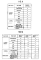
- FIG. 18 shows initial priority of each of totally twelve tasks constituting the communication task group, the control task group and the management task group of FIG. 17 (a smaller value means higher priority).
- priority of the task group execution mode switching 15 is set to 2.
- the task group execution mode switching 15 is operated to add priority of priority deviation of FIG. 3 to these tasks during mode switching. As a result, priority of the task on each mode becomes similar to that shown in FIG. 19.
- priority deviation during switching of last mode ⁇ first mode i.e., mode 2 ⁇ mode 0 of FIG. 3 is used.
- initial priority 3 is added to priority deviation 18 of mode 2 ⁇ mode 0 to make 21.
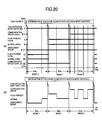
- FIG. 20(a) is a graph showing FIG. 19 by a time chart. For example, on the mode 0, after execution of task execution mode switching, tasks for the management task group, the control group and the communication group are executed from those high in priority.
- FIG. 20(b) is a graph showing a time chart of an execution example of each task. As shown in the graph of FIG. 20(b), after an occurrence of interruption for execution mode switching by the execution counter, at a mode starting time, the task group execution mode switching 15 is executed, and task priority is changed. In a time zone of the mode 0, the management task group is preferentially executed; on the mode 1, the control task group; and on the mode 2, the communication task group.
- task group suspension/resumption of FIG. 11 is carried out.
- execution modes There are three types of execution modes, i.e., a mode 0, a mode 1 and a mode 2, and an execution state of the task group is changed during execution mode switching.
- a value of mode duration set in the execution counter is similar to that shown in FIG. 14.
- Task group information has a structure similar to that shown in FIG. 5 or 6, and an operation of the task group suspension/resumption processing 1531 is similar to that shown in FIG. 13.
- Initial priority of each of totally twelve tasks constituting the communication task group, the control task group and the management task group of FIG. 17 is similar to that shown in FIG. 18 (a smaller value means higher priority).
- priority of the task group execution mode switching 15 must be higher than priority of any one of the tasks in the task group of FIG. 17.
- priority of the task group execution mode switching is set to 2.
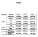
- FIG. 21 shows an execution state of a task on each mode, as a result of changes made in the execution states of the totally seven tasks 1 to 7 of FIG. 1 by the operation of the task group execution mode switching 15 during mode switching of FIG. 12.
- suspension means one of forcible standby states (SUSPENDED or WAITING-SUSPENDED). This is equivalent to, when a need arises to suspend a task because of mode switching, any one of the following states, in which the task has been, i.e., an execution state (RUNNING), an executable state (READY) and a standby state (WAITING). Conversely, execution means a return of a task state to one selected from RUNNING, READY and WAITING. In a dormant state of a task (DORMANT), no state changes are made irrespective of task suspension/execution.
- DORMANT dormant state of a task
- Execution states of the task groups on respective modes are as follows:
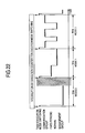
- FIG. 22 is a graph showing a time chart of an execution example of each task of FIG. 21.
- the task group execution mode switching 15 is executed, and changes are made in execution states of the tasks.
- a time zone of the mode since the control task group and the communication task group are both suspended, only the management task group is executed.
- execution of the control task group is resumed, and execution is made preferentially from the management task group.
- execution of the communication task group is resumed, and this group is preferentially executed before the other task groups.
- An advantage of the second embodiment of the task group execution mode switching 15 is basically similar to that of the first embodiment. A difference is that since the CPU becomes idle more frequency than in the first embodiment, and processing time is shorter for the task suspension/resumption than for the changing of the priority of the tasks of the first embodiment during mode switching, overhead is smaller than that of the first embodiment during mode switching.
- FIG. 23 shows a third embodiment of task group execution mode switching 15.
- the task group execution mode switching 15 includes an execution mode 151, an execution counter 152, task group priority changing 1532, task group information 154, and a pattern 154.
- the execution mode 151, the execution counter 152, and the task group information 154 are basically similar to those of the previous embodiments.
- processing for referring/updating the pattern 155 is added to the previous embodiment, which will be described in detail later.
- the task execution mode switching 15 includes Interruption processing or a task. In the latter case, priority of the task execution mode switching 15 is set highest, or at least higher than priority of any tasks constituting the task group as a target to be monitorially controlled.
- the setting of mode duration in the execution counter was fixed in the first embodiment. In the described embodiment, however, on each pattern, flexibility is provided in this regard.
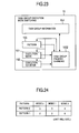
- the mode duration set in the execution counter shown in FIG. 4 is defined as one pattern and, by providing a plurality of such patterns as shown in FIG. 24, the task group execution switching 15 can be operated in any patterns. Identification of this pattern is achieved by the pattern 155.
- duration of a mode 0 is set to 3 milli-sec.; duration of a mode 1 to 3 milli-sec.; and duration of a mode 2 to 4 milli-sec. (similar to that shown in FIG. 4, and one cycle is set to 10 milli-sec.)
- duration of the mode 0 is set to 2 milli-sec.; duration of the mode 1 to 2 milli-sec.; and duration of the mode 2 to 6 milli-sec.
- FIG. 24 shows only an example. Thus, needless to say, a value of mode duration set on each execution mode, the number of modes, and the number of patterns can be optionally set.
- the task execution mode switching 15 is actuated (9081).
- the task group priority changing 1532 first refers to pattern information set in the pattern 155 (90811), and updates an execution mode (9082). The updating of the execution mode is achieved by calculation described below.
- New execution mode number previous execution mode (number of all (number+1)% modes)
- duration of the new execution mode is set in the execution counter (9083).
- one task group to be edited is taken out by referring to the task group information 154 (9084). Then, for all tasks registered in the task group (9085), task priority is updated (9086). The updating is achieved by calculation below.
- Priority of task of current execution mode priority of previous execution mode+priority deviation during switching to current mode of task group to which it belongs (see a list of priority deviation of task group during mode switching)
- the above-described calculation is carried out for all the tasks of all the task groups registered in the task group information 154.
- execution modes there are three types of execution modes, i.e., a mode 0, a mode 1 and a mode 2 and, as shown in FIG. 3, priority deviation of the task groups is obtained during execution mode switching.
- a value of mode duration set in the execution counter is similar to that shown in FIG. 24.
- the task group information 154 has a structure similar to that of FIG. 5 or 6, and an operation of the task group priority changing 1532 is similar to that shown in FIG. 25.
- Initial priority of each of totally twelve tasks constituting the communication task group, the control task group, and the management task group of FIG. 17 is similar to that shown in FIG. 18 (a smaller value means higher priority). Though not shown, priority of the task group execution mode switching 15 is set to 2.
- the task group execution mode switching 15 is operated to add priority of priority deviation of FIG. 3 to these tasks during mode switching.
- priority of the task on each mode becomes similar to that shown in FIG. 19.
- priority deviation during switching of last mode ⁇ first mode i.e., mode 2 ⁇ mode 0 of FIG. 3 is used.
- Higher and lower relations in priority among the group execution mode switching 15 and the task groups on each execution mode are as follows:
- FIG. 26 is a graph showing a time chart when pattern switching occurs. As shown in the graph, after interruption occurs for execution mode switching by the execution counter, at each mode starting time, the task group execution mode switching 15 is executed to change task priority.
- a management task group is preferentially executed; on a mode 1, a control task group; and on mode 2, a communication task group.
- a pattern changing request is made (in the drawing, in the midway of first mode 2)
- patterns are switched from the pattern 0 to a pattern 1 at next mode switching time, i.e., switching of mode 2 ⁇ mode 0, and durations of the modes 0, 1 and 2, which have been respectively 3 milli-sec., 3 milli-sec., and 4 milli-sec., are changed to 2 milli-sec., 2 milli-sec., and 6 milli-sec., after the pattern changing.
- the pattern 155 was applied for the first embodiment of the task group execution mode switching 15, i.e., priority changing of the task groups. Needless to say, however, it can also be applied to the second embodiment of the task group execution mode switching 15, i.e., task group suspension/resumption processing.
- the total number of modes for each pattern was unchanged, and only the value of mode duration in the execution counter was changed.
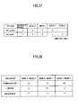
- FIG. 27 for each pattern, it is possible to change not only the number of modes, and mode duration set in each execution counter, but also the number of modes set therein.
- the number of modes is set to 3; duration of a mode 0 is set to 3 milli-sec.; duration of a mode 1 to 3 milli-sec.; and duration of a mode 2 to 4 milli-sec. (similar to that shown in FIG. 4, and one cycle is set to 10 milli-sec.).
- the number of modes is set to 4; duration of the mode 0 is set to 3 milli-sec.; duration of the mode 1 to 2 milli-sec.; duration of the mode 2 to 1 milli-sec.; and duration of the mode 3 to 4 milli-sec.
- FIG. 27 shows only an example. Thus, needless to say, a value of mode duration set on each execution mode, the number of modes, and the number of patterns can be optionally set.
- FIG. 28 shows a list of priority deviation of the task groups during mode switching in the pattern 0.
- FIG. 28 is similar to FIG. 3, where mode switching of the pattern 0 is similar to that of the pattern 0 of the previous embodiment, or the mode switching of the first embodiment.
- FIG. 29 shows a list of priority deviation of the task groups during mode switching in the pattern 1.
- execution modes i.e., a mode 0, a mode 1, a mode 2, and a mode 3, and the modes are cyclically switched as follows: Mode 0 ⁇ mode 1 ⁇ mode 2 ⁇ mode 3 ⁇ mode 0 ⁇ ⁇
- priority of deviation is added to all the tasks in each task group.
- priority of the task on each mode becomes similar to that shown in FIG. 19 as in the case of the pattern 0 of the previous embodiment.
- Higher and lower relations in priority among the group execution mode switching 15 and the task groups on each execution mode are as follows:
- the task group execution mode switching 15 is operated to add priority of priority deviation of FIG. 29 to the tasks during mode switching.
- priority of the task on each mode of the pattern 1 becomes similar to that shown in FIG. 30.
- Higher and lower relations in priority among the group execution mode switching 15 and the task groups on each execution mode are as follows:
- FIG. 31 is a graph showing a time chart of task execution of the embodiment. As shown in the graph of FIG. 31, in the pattern 0, as in the case of FIG. 20(b), after interruption occurs for execution mode switching by the execution counter, at each mode starting time, the task group execution mode switching 15 is executed to change task priority.
- a pattern changing request is made (in the drawing, in the midway of first mode 2)
- patterns are switched from the pattern 0 to the pattern 1 at next mode switching time, i.e., switching of mode 2 ⁇ mode 0, and durations of the modes 0, 1 and 2, which have been respectively 3 milli-sec., 3 milli-sec., and 4 milli-sec., are changed, with one mode added to make the mode 0, the model, the mode 2, and the mode 3, to 3 milli-sec., 2. milli-sec., 1 milli-sec., and 4 milli-sec., after the pattern changing.
- the controller 1 of the invention even if a change occurs in an operation situation of the system, to which the controller 1 of the invention is applied, switching can be made to a running state suitable for the operation situation more flexibly than that first shown in the third embodiment. Thus, the controller 1 can be efficiently operated.
- the pattern 155 was applied for the first embodiment of the task group execution mode switching 15, i.e., priority changing of the task groups. Needless to say, however, it can also be applied to the second embodiment of the task group execution mode switching 15, i.e., task group suspension/resumption processing.
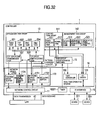
- FIG. 32 is a view focusing on a software configuration operated on the controller of FIG. 17, where a pattern changing request (switching command of a running pattern) can be issued to the task execution mode switching 15 by the receiving buffer 1732 in the network driver 172.
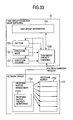
- FIG. 33 shows the task execution mode switching 15 cut out from the receiving buffer 1732 in the network driver 172 of FIG. 32.
- the task group execution mode switching 15 is similar to that shown in FIG. 23.
- the network driver 172 is constructed as received information monitoring means for monitoring a quantity of communication information obtained from communications with the LAN 40, and outputting a pattern changing request (switching command of a running state) to the task group execution mode switching 15 in accordance with the quantity of received information.
- receiving buffer management 1731 incorporates a receiving buffer vacancy monitor 17311.
- the receiving buffer vacancy monitor 17311 monitors a use situation of the receiving buffer 1732, and issues a pattern changing request to the task group execution mode switching 15 when buffer vacancy is reduced.
- FIG. 34 shows an operation flow of the receiving buffer vacancy monitor 17311.
- the current pattern is compared with the new pattern (9095) and, if both coincide with each other, the process returns to 9092.
- the patterns 0 and 1 of FIG. 34 are equivalent to, for example, the patterns 0 and 1 of the third embodiment and the supplemental embodiment of the task group execution mode 15 described above.
- a vacant area is reduced to make a change of pattern 0 ⁇ pattern 1, increasing a time zone where the communication task group is preferentially executed.
- a probability of overflowing of the receiving buffer can be reduced.
- the embodiment has been described with reference to the case where the task group execution mode switching 15 changes priority of the task groups. However, the embodiment can also be applied to a case of task group suspension/resumption.
- vacancy monitoring of the receiving buffer was described. Needless to say, however, vacancy monitoring of the transmission buffer can be executed.
- the network driver 172 of the embodiment was mainly by software. However, as shown in FIG. 38, all or a part of functions of the network driver 172 can be realized by hardware. FIG. 38 shows an example where a function of the network driver 172 is realized by hardware on the network control circuit 11.
- the communication task group was controlled by changing task priority or suspension/resumption. Now, description is made of a simple and small overhead method for controlling the communication task group.
- FIG. 35 shows an arrangement where a control register 1101 in the network control circuit 11 can be controlled by the task group execution mode switching 15 in FIG. 32.
- the setting of the control register 1101 generally enables reception/transmission interruption from the network control circuit 11 to be masked. Accordingly, instead of priority changing or suspension/resumption by the task group execution mode switching 15, interruption from the network control circuit 11 is masked or unmasked by the setting of the control register 1101, and thus the operation of the communication task group is controlled.
- FIG. 36 shows an example of changing control register setting of the network control circuit during mode switching.
- mode 2 ⁇ mode 0 the setting of the control register 1101 is changed in order to mask interruption from the network control circuit 11.
- mode 0 ⁇ mode 1 no setting changes are made.
- mode 1 ⁇ mode 2 the setting of the control register 1101 is changed in order to unmask the interruption from the network control circuit 11.
- priority of the communication task group is higher than any other task groups, as shown in FIG. 18.
- a TCP, UDP, IP and ICMP transmission task 507, and a TCP, UDP, IP and ICMP receiving task 508 of FIG. 35 are not actuated by the network control circuit 11.
- the receiving task 508 is not actuated, and higher-order communication application tasks 501 to 504 are not actuated.
- other task groups are preferentially executed.
- interruption occurs from the network control circuit 11, and the network task group is normally actuated.
- priority of the communication task group is higher than any other tasks, this task group is executed before the others.
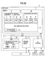
- the task execution mode switching 15 of the embodiment was mainly by software. However, as shown in FIG. 39, all or a part of functions of the task execution mode switching 15 can be realized by hardware. FIG. 39 shows an example where a function of the task execution mode switching 15 is realized by hardware on the CPU 100.
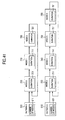
- the task execution control switching 15 carries out the task execution control, such as priority changing of the task groups, suspension/resumption or the like in accordance with the execution mode. Further, as shown in FIG. 40, the task execution mode switching 15 is made a part of the function of the real-time operating system 16 and, accordingly, the above execution control is released to a user as a system call described below. Thus, from an application program prepared by the user, control by the task group execution mode switching 15 that has been described can be easily executed.
- FIG. 42 shows a configuration example of a remote monitorial control system using the controller 1 of the invention.
- Access to the controller 1 is made by personal computers, work stations, various information portable terminals (PDA), portable telephone sets or the like (in the drawing, PC 201 to 20k (k is a positive integer) connected to a LAN 40.
- Devices 301 to 30n (n is a positive integer) connected to the controller 1 can be monitored, operated and controlled.
- LAN40 in FIG. 42 may be not only a local network, but a public network such as public telephone, Internet or the like.
- FIG. 43 shows an embodiment of a decentralized control system using the controller 1 of the invention.
- a plurality of controllers 121 to 12m (m is a positive integer) of the invention are connected. By executing communications among these controllers, gang control, monitoring from a host computer, an operation and control are carried out.
- FIG. 43 as in the case of FIG. 42, work stations, various information portable terminals (PDA), portable telephone sets or the like (in the drawing, PC 201 to 20k (k is a positive integer) are connected to a LAN 40.
- PDA information portable terminals
- devices 301 to 30n, 311 to 31p, and 321 to 32q (n, p and q are positive integers) connected to the controller 1 are monitored, operated and controlled from a remote area.
- the LAN 40 may be a local network, a public network such as public telephone, Internet or the like.
Landscapes
- Physics & Mathematics (AREA)
- General Physics & Mathematics (AREA)
- Engineering & Computer Science (AREA)
- Automation & Control Theory (AREA)
- Data Exchanges In Wide-Area Networks (AREA)
- Computer And Data Communications (AREA)
- Small-Scale Networks (AREA)
- Multi Processors (AREA)
- Programmable Controllers (AREA)
Abstract
Description
At present, generally, priority assignment is first carried out in a fixed manner among operations (tasks) including control processing, network communication processing and the like, and then these tasks are executed and managed by using priority scheduling of a real-time OS. As an example of priority scheduling of the real-time OS available in the conventional art, "µITRON 4.0 Specifications" Chap. 3.2 (ITRON Division of TRON Association, edited by Hiroaki Takada under monitoring of Ken Sakamura) can be cited.
In addition, during mode switching shown below, priority of deviation is added to all the tasks in each task group.
- 18 is added to priority of all the tasks in the communication task group,
- 12 is added to priority of all the tasks in the control task group, and
- no changes are made in priority of all the tasks in the management task group.
- no changes are made in priority of all the tasks in the communication task group,
- -12 is added (12 is subtracted) to priority of all the tasks in the control task group, and
- no changes are made in priority of all the tasks in the management task group.
- -18 is added (18 is subtracted) to priority of all the tasks in the communication task group,
- no changes are made in priority of all the tasks in the control task group, and
- no changes are made in priority of all the tasks in the management task group.
By referring to a mode duration value set in the execution counter (FIG. 4), duration of the new execution mode is set in the execution counter (9083).
There are no changes made in a higher and lower relation in priority among the tasks of each task group.
In this case, an execution mode of each task group is changed as follows during mode switching:
- all tasks in a communication task group are suspended,
- all tasks in a control task group are suspended, and
- no changes are made in execution states of all tasks in management tasks.
- no changes are made in execution states of all the tasks in the communication task group,
- execution of all the tasks in the control task group is resumed or started, and
- no changes are made in execution states of all the tasks in the management task group.
- execution of all the tasks in the communication task group is resumed,
- no changes are made in execution states of all the tasks in the control task group, and
- no changes are made in execution states of all the tasks in the management task group.
There are no changes made in a higher and lower relation in priority among the tasks of each task group.
By referring to a list of mode duration values set in the execution counter for a current pattern, duration of the new execution mode is set in the execution counter (9083).
There are no changes made in a higher and lower relation in priority among the tasks of each task group.
Here, when a pattern changing request is made (in the drawing, in the midway of first mode 2), patterns are switched from the
In addition, during mode switching shown below, priority of deviation is added to all the tasks in each task group.
- 18 is added to priority of all the tasks in the communication task group,
- 12 is added to priority of all the tasks in the control task group,
- no changes are made in priority of all the tasks in the management task group.
- no changes are made in priority of all the tasks in the communication task group,
- -12 is added (12 is subtracted) to priority of all the tasks in the control task group, and
- no changes are made in priority of all the tasks in the management task group.
- -15 is added (15 is subtracted) to priority of all the tasks in the communication task group,
- no changes are made in priority of all the tasks in the control task group, and
- no changes are made in priority of all the tasks in the management task group.
- -3 is added (3 is subtracted) to priority of all the tasks in the communication task group,
- no changes are made in priority of all the tasks in the control task group, and
- no changes are made in priority of all the tasks in the management task group.
- Generation and deletion of task group
- Task member registration and deletion in task group
- Priority changing of task group unit
- Suspension/resumption of task group unit
- Setting of duration in execution mode
- Generation and deletion of pattern
- Mode member registration and deletion in pattern
Specifically, a structure for managing the
- Erercd Normal end (E_OK) or error code
Specifically, the structure for managing the task groups of FIG. 6 is deleted.Parameter:
- Erercd Normal end (E_OK) or error code
- Erercd Normal end (E_OK) or error code
- Erercd Normal end (E_OK) or error code
- GID tsk_gid ID number of target task group
- DELTA_PRI delta_tskpri priority addition (negative value can be set)
- Erercd Normal end (E_OK) or error code
- ER ercd Normal end (E_OK) or error code
- ER ercd Normal end (E_OK) or error code
- ER ercd Normal end (E_OK) or error code
- MID mdid ID number of execution mode to be deleted
- ER ercd Normal end (E_OK) or error code
Specifically, a structure for managing the
- ER ercd Normal end (E_OK) or error code
- ER ercd Normal end (E_OK) or error code
- ER ercd Normal end (E_OK) or error code
- ER ercd Normal end (E_OK) or error code
Claims (18)
- A controller (1) which is provided with a plurality of tasks and a program including an operating system (16) for controlling the execution of the tasks, wherein the plurality of tasks are managed by being classified into a communication task group (13) for performing communications with a network communication system and a control task group (141) for monitorially controlling a target to be monitorially controlled; an execution order of the plurality of tasks are switched by a group unit; and in accordance with the switched task group, information obtained from the target to be monitorially controlled or the network communication system is processed.
- A controller (1) comprising a memory (17) for storing a plurality of tasks and a program including an operating system (16) for controlling the execution of the tasks; an I/O interface (10) for transferring information with a target to be monitorially controlled; a network control circuit (11) for transferring information with a network communication system; a microprocessor (100) for processing either of the information in accordance with the program stored in the memory; and task switching means for managing the plurality of tasks stored in the memory by classifying them into a communication task group (13) for performing network communications and a control task group (141) for monitorially controlling the target to be monitorially controlled, and for switching an execution order of the plurality of tasks by a group unit.
- A controller according to claim 2, comprising a management task group (142) for management including the internal monitoring of the microprocessor.
- The controller according to claim 2, wherein said task switching means switches the execution order of the plurality of tasks by the group unit in accordance with priority in response to a switching command.
- The controller according to claim 4, wherein said task switching means uniformly changes priority of all the tasks in the group when switching the execution order of the plurality of tasks by the group unit in accordance with the priority.
- The controller according to claim 2, wherein said task switching means switches the execution order of the plurality of tasks by the group unit in response to a switching command, and uniformly suspends/resumes execution of all the tasks in a group for which execution of the tasks is to be suspended/resumed.
- The controller according to claim 4, wherein said task switching means switches the execution order of the plurality of tasks by the group unit in accordance with an execution mode for giving priority to communications with the network communication system over control of the target to be monitorially controlled, or an execution mode for giving priority to the control of the target to be monitorially controlled over the communications with the network communication system.
- The controller according to claim 7, wherein said task switching means manages operation patterns including the execution mode giving priority to the communications and the execution mode giving priority to the control by classifying them into a plurality of operation patterns, switches the plurality of operation patterns in response to an operation pattern switching command, manages execution time of each execution mode for the switched operation pattern, and instructs switching to the other execution mode after a passage of each execution time.
- The controller according to claim 3, wherein said task switching means switches the execution order of the plurality of tasks by the group unit in accordance with an execution mode giving priority to communications with the network communication system over control of the target to be monitorially controlled, an execution mode giving priority to the control of the target to be monitorially controlled over the communications with the network communication system, or an execution mode giving priority to management over each of the modes.
- The controller according to claim 7, wherein said task switching means manages execution time of each execution mode, and instructs switching to the other execution mode after a passage of each execution time.
- The controller according to claim 9, wherein said task switching means manages operation patterns including the execution mode giving priority to the communications, the execution mode giving priority to the control, and the execution mode giving priority to the management over each of the execution modes by classifying them into a plurality of operation patterns, switches the plurality of operation patterns in response to an operation pattern switching command, manages execution time of each execution mode for the switched operation pattern, and instructs switching to the other execution mode after a passage of each execution time.
- The controller according to claim 8, which further comprises received information monitoring means for monitoring a quantity of received information obtained from communications with the network communication system, said received information monitoring means instructing the task switching means to switch to an operation pattern in accordance with the quantity of received information.
- A controller (1) comprising a plurality of tasks for performing communications and control; and task switching means for managing the plurality of tasks by classifying them into a communication task group (13) for communicating with a network communication system and a control task group (141) for monitorially controlling a target to be monitorially controlled, and for switching an execution order of the plurality of tasks by a group unit.
- A controller (1) comprising a plurality of tasks for performing each of communications, control and management; and task switching means for managing the plurality of tasks by classifying them into a communication task group (13) for performing communications with a network communication system, a control task group (141) for monitorially controlling a target to be monitorially controlled, and a management task group (142) for management, and for switching an execution order of the plurality of tasks by a group unit can be used.
- An operating system (16) comprising a system call for managing a plurality of tasks every group unit by classifying them into a plurality of groups, and for switching an execution order of the plurality of tasks by the group unit.
- The operating system according to claim 15, wherein said system call switches the execution order of the plurality of tasks by the group unit in accordance with priority in response to a switching command, and uniformly changes priority of all the tasks in the group.
- A remote monitorial control system comprising the controller according to claim 1, and an information terminal connected to the network communication system.
- A distributed control system comprising the plurality of controllers according to claim 1, wherein the respective controllers are disposed in a distributed manner.
Priority Applications (1)
| Application Number | Priority Date | Filing Date | Title |
|---|---|---|---|
| EP06021738A EP1746473A1 (en) | 2001-08-30 | 2002-04-18 | Controller and operating system |
Applications Claiming Priority (2)
| Application Number | Priority Date | Filing Date | Title |
|---|---|---|---|
| JP2001261469 | 2001-08-30 | ||
| JP2001261469A JP2003067201A (en) | 2001-08-30 | 2001-08-30 | Controller and operating system |
Related Child Applications (1)
| Application Number | Title | Priority Date | Filing Date |
|---|---|---|---|
| EP06021738A Division EP1746473A1 (en) | 2001-08-30 | 2002-04-18 | Controller and operating system |
Publications (3)
| Publication Number | Publication Date |
|---|---|
| EP1288748A2 true EP1288748A2 (en) | 2003-03-05 |
| EP1288748A3 EP1288748A3 (en) | 2004-12-22 |
| EP1288748B1 EP1288748B1 (en) | 2007-01-17 |
Family
ID=19088515
Family Applications (2)
| Application Number | Title | Priority Date | Filing Date |
|---|---|---|---|
| EP06021738A Withdrawn EP1746473A1 (en) | 2001-08-30 | 2002-04-18 | Controller and operating system |
| EP02008241A Expired - Lifetime EP1288748B1 (en) | 2001-08-30 | 2002-04-18 | Controller and operating system |
Family Applications Before (1)
| Application Number | Title | Priority Date | Filing Date |
|---|---|---|---|
| EP06021738A Withdrawn EP1746473A1 (en) | 2001-08-30 | 2002-04-18 | Controller and operating system |
Country Status (4)
| Country | Link |
|---|---|
| US (2) | US6993765B2 (en) |
| EP (2) | EP1746473A1 (en) |
| JP (1) | JP2003067201A (en) |
| DE (1) | DE60217593T2 (en) |
Cited By (2)
| Publication number | Priority date | Publication date | Assignee | Title |
|---|---|---|---|---|
| EP2207070A1 (en) | 2009-01-09 | 2010-07-14 | Yokogawa Electric Corporation | Field control device and field control method |
| WO2016083986A1 (en) * | 2014-11-30 | 2016-06-02 | Abb Technology Ltd. | Method for ensuring execution of a plant process in a distributed control system |
Families Citing this family (50)
| Publication number | Priority date | Publication date | Assignee | Title |
|---|---|---|---|---|
| KR100654414B1 (en) * | 2002-03-22 | 2006-12-05 | 도요다 지도샤 가부시끼가이샤 | Computer-readable recording medium recording task management apparatus and method thereof, task management program |
| US6938111B2 (en) * | 2002-04-19 | 2005-08-30 | Siemens Aktiengesellschaft | Method for operating automation control equipment applications |
| FR2841013B1 (en) * | 2002-06-12 | 2004-09-03 | Mbda France | EVENT MANAGEMENT METHOD AND SYSTEM |
| JP3938343B2 (en) * | 2002-08-09 | 2007-06-27 | インターナショナル・ビジネス・マシーンズ・コーポレーション | Task management system, program, and control method |
| US20050039184A1 (en) * | 2003-08-13 | 2005-02-17 | Intel Corporation | Assigning a process to a processor for execution |
| US20050049847A1 (en) * | 2003-08-29 | 2005-03-03 | Oki Electric Industry Co., Ltd. | Software development environment and method for measuring software performance |
| JP4682513B2 (en) * | 2003-12-05 | 2011-05-11 | トヨタ自動車株式会社 | Task management system |
| US7693847B1 (en) * | 2004-07-13 | 2010-04-06 | Teradata Us, Inc. | Administering workload groups |
| US8015373B2 (en) * | 2005-05-13 | 2011-09-06 | Hewlett-Packard Development Company, L.P. | Information sharing between a backup storage device and a management appliance |
| JP4300196B2 (en) * | 2005-05-26 | 2009-07-22 | 株式会社東芝 | Command execution device, command execution method, and command execution program |
| US8146090B2 (en) | 2005-09-29 | 2012-03-27 | Rockstar Bidco, LP | Time-value curves to provide dynamic QoS for time sensitive file transfer |
| US7941596B2 (en) * | 2005-10-26 | 2011-05-10 | Hewlett-Packard Development Company, L.P. | Locating media by characteristics in storage apparatus |
| US7954106B2 (en) * | 2005-12-19 | 2011-05-31 | British Telecommunications Public Limited Company | Estimating resource usage system for allocating resources to tasks based upon the rating value of tasks and resources mapping |
| JP2007195131A (en) * | 2005-12-19 | 2007-08-02 | Mitsubishi Heavy Ind Ltd | Control device and communication program |
| US7568198B2 (en) * | 2006-01-10 | 2009-07-28 | National Instruments Corporation | Control of tasks in a programmable logic controller |
| US7565654B2 (en) * | 2006-01-10 | 2009-07-21 | National Instruments Corporation | Programmatic control of tasks in a programmable logic controller |
| US8347295B1 (en) | 2006-03-23 | 2013-01-01 | Emc Corporation | Profile-based assignment of queued tasks |
| US8826280B1 (en) | 2006-03-23 | 2014-09-02 | Emc Corporation | Processing raw information for performing real-time monitoring of task queues |
| US8539493B1 (en) * | 2006-03-23 | 2013-09-17 | Emc Corporation | Configurable prioritization and aging of queued tasks |
| JP2007316721A (en) * | 2006-05-23 | 2007-12-06 | Toshiba Corp | Mobile device |
| JP4770664B2 (en) * | 2006-09-20 | 2011-09-14 | 株式会社デンソー | Microprocessor and microcomputer using the same |
| US8694999B2 (en) * | 2006-12-07 | 2014-04-08 | Wind River Systems, Inc. | Cooperative scheduling of multiple partitions in a single time window |
| JP4874140B2 (en) | 2007-03-20 | 2012-02-15 | 京セラミタ株式会社 | Job scheduler, job scheduling method, and job control program |
| JP2008276569A (en) * | 2007-04-27 | 2008-11-13 | Toshiba Corp | Information processing device |
| EP1993009A1 (en) * | 2007-05-16 | 2008-11-19 | Tac AB | Controller, system, method and computer programs for building control |
| JP4650697B2 (en) * | 2007-06-06 | 2011-03-16 | エヌイーシーコンピュータテクノ株式会社 | CPU resource management method |
| JP2009169790A (en) * | 2008-01-18 | 2009-07-30 | Nec Electronics Corp | Task controller and task control method |
| JP5053109B2 (en) | 2008-01-23 | 2012-10-17 | 株式会社日立製作所 | Control device |
| US8930946B1 (en) * | 2008-02-14 | 2015-01-06 | Google Inc. | Leasing prioritized tasks |
| US8706858B2 (en) * | 2008-04-17 | 2014-04-22 | Alcatel Lucent | Method and apparatus for controlling flow of management tasks to management system databases |
| US20120159336A1 (en) * | 2009-03-27 | 2012-06-21 | Michael Roy Norwood | Electronic list priority management system and method of using same |
| US8959517B2 (en) * | 2009-06-10 | 2015-02-17 | Microsoft Corporation | Cancellation mechanism for cancellable tasks including stolen task and descendent of stolen tasks from the cancellable taskgroup |
| FR2956226B1 (en) * | 2010-02-10 | 2012-12-14 | Airbus Operations Sas | METHOD, COMPUTER PROGRAM AND CONTROLLER SUPERVISION DEVICE FOR MANAGING PROCESS TIME SHARING IN A MULTI-HAND COMPUTING SYSTEM |
| EP2477085B1 (en) * | 2011-01-13 | 2013-07-17 | Siemens Aktiengesellschaft | System and method for analysing a time behaviour of the execution of a control program in an industrial control device |
| CN103443770B (en) | 2011-03-19 | 2017-12-12 | 富士通株式会社 | Terminal installation, process management method and process supervisory program |
| JPWO2012131961A1 (en) * | 2011-03-30 | 2014-07-24 | 富士通株式会社 | Data processing method and portable terminal |
| GB2491165A (en) | 2011-05-26 | 2012-11-28 | Realvnc Ltd | Mobile device having a priority adjusting thread for link wi th remote terminal |
| US9280386B1 (en) * | 2011-07-14 | 2016-03-08 | Google Inc. | Identifying task instance outliers based on metric data in a large scale parallel processing system |
| JP5949421B2 (en) * | 2012-10-11 | 2016-07-06 | 富士通株式会社 | Information processing apparatus, execution priority changing method, and program |
| EP2778915A1 (en) * | 2013-03-13 | 2014-09-17 | Siemens Aktiengesellschaft | Method for operating an industrial control system and industrial control system |
| JP5881753B2 (en) * | 2014-01-20 | 2016-03-09 | 三菱電機株式会社 | Control unit and vehicle control apparatus using the same |
| WO2016084212A1 (en) * | 2014-11-28 | 2016-06-02 | 株式会社日立製作所 | Control server and grouping method for control applications |
| US9486921B1 (en) * | 2015-03-26 | 2016-11-08 | Google Inc. | Methods and systems for distributing remote assistance to facilitate robotic object manipulation |
| JP6365387B2 (en) * | 2015-04-20 | 2018-08-01 | 株式会社デンソー | Electronic control unit |
| CN105955179B (en) * | 2016-05-05 | 2019-06-07 | 中工科安科技有限公司 | A kind of Integral small-sized PLC and its automatic identifying method for extending I/O module |
| US10761542B1 (en) | 2017-07-11 | 2020-09-01 | Waymo Llc | Methods and systems for keeping remote assistance operators alert |
| JP6833649B2 (en) * | 2017-09-22 | 2021-02-24 | 株式会社日立産機システム | Programmable controller and control system |
| CN109960178B (en) * | 2017-12-26 | 2020-10-16 | 深圳市优必选科技有限公司 | Robot and joint motion control method and device thereof |
| CN110275401B (en) * | 2018-03-15 | 2022-10-28 | 柯尼卡美能达办公系统研发(无锡)有限公司 | Optional device monitoring device, image forming apparatus, and monitoring method |
| WO2020039538A1 (en) | 2018-08-23 | 2020-02-27 | 三菱電機株式会社 | Communication device, communication method, and communication program |
Family Cites Families (16)
| Publication number | Priority date | Publication date | Assignee | Title |
|---|---|---|---|---|
| US4642756A (en) * | 1985-03-15 | 1987-02-10 | S & H Computer Systems, Inc. | Method and apparatus for scheduling the execution of multiple processing tasks in a computer system |
| US4888726A (en) * | 1987-04-22 | 1989-12-19 | Allen-Bradley Company. Inc. | Distributed processing in a cluster of industrial controls linked by a communications network |
| US5193189A (en) * | 1987-10-07 | 1993-03-09 | Allen-Bradley Company, Inc. | Programmable controller with multiple priority level task processing |
| US5504894A (en) * | 1992-04-30 | 1996-04-02 | International Business Machines Corporation | Workload manager for achieving transaction class response time goals in a multiprocessing system |
| US5528513A (en) * | 1993-11-04 | 1996-06-18 | Digital Equipment Corp. | Scheduling and admission control policy for a continuous media server |
| US5487170A (en) * | 1993-12-16 | 1996-01-23 | International Business Machines Corporation | Data processing system having dynamic priority task scheduling capabilities |
| US5712976A (en) * | 1994-09-08 | 1998-01-27 | International Business Machines Corporation | Video data streamer for simultaneously conveying same one or different ones of data blocks stored in storage node to each of plurality of communication nodes |
| US5636124A (en) * | 1995-03-08 | 1997-06-03 | Allen-Bradley Company, Inc. | Multitasking industrial controller |
| JPH0954699A (en) * | 1995-08-11 | 1997-02-25 | Fujitsu Ltd | Computer process scheduler |
| JPH09251389A (en) | 1996-03-14 | 1997-09-22 | Omron Corp | Data processing device |
| JPH1021094A (en) | 1996-07-08 | 1998-01-23 | Mitsubishi Electric Corp | Real-time control method |
| DE19744230B4 (en) | 1997-10-07 | 2007-10-25 | Robert Bosch Gmbh | Control units for a system and method for operating a control unit |
| JP4072271B2 (en) | 1999-02-19 | 2008-04-09 | 株式会社日立製作所 | A computer running multiple operating systems |
| US6757897B1 (en) * | 2000-02-29 | 2004-06-29 | Cisco Technology, Inc. | Apparatus and methods for scheduling and performing tasks |
| US20030037091A1 (en) * | 2001-08-09 | 2003-02-20 | Kozo Nishimura | Task scheduling device |
| US7793294B2 (en) * | 2005-02-22 | 2010-09-07 | Northrop Grumman Corporation | System for scheduling tasks within an available schedule time period based on an earliest possible end time of the task |
-
2001
- 2001-08-30 JP JP2001261469A patent/JP2003067201A/en active Pending
-
2002
- 2002-03-20 US US10/101,570 patent/US6993765B2/en not_active Expired - Fee Related
- 2002-04-18 EP EP06021738A patent/EP1746473A1/en not_active Withdrawn
- 2002-04-18 EP EP02008241A patent/EP1288748B1/en not_active Expired - Lifetime
- 2002-04-18 DE DE60217593T patent/DE60217593T2/en not_active Expired - Lifetime
-
2005
- 2005-11-03 US US11/265,226 patent/US20060059491A1/en not_active Abandoned
Cited By (2)
| Publication number | Priority date | Publication date | Assignee | Title |
|---|---|---|---|---|
| EP2207070A1 (en) | 2009-01-09 | 2010-07-14 | Yokogawa Electric Corporation | Field control device and field control method |
| WO2016083986A1 (en) * | 2014-11-30 | 2016-06-02 | Abb Technology Ltd. | Method for ensuring execution of a plant process in a distributed control system |
Also Published As
| Publication number | Publication date |
|---|---|
| US20030046324A1 (en) | 2003-03-06 |
| US6993765B2 (en) | 2006-01-31 |
| US20060059491A1 (en) | 2006-03-16 |
| JP2003067201A (en) | 2003-03-07 |
| EP1288748B1 (en) | 2007-01-17 |
| EP1288748A3 (en) | 2004-12-22 |
| EP1746473A1 (en) | 2007-01-24 |
| DE60217593D1 (en) | 2007-03-08 |
| DE60217593T2 (en) | 2007-10-25 |
Similar Documents
| Publication | Publication Date | Title |
|---|---|---|
| US6993765B2 (en) | Controller and operating system | |
| US7411966B2 (en) | Method and system for coupling data networks | |
| JP7000686B2 (en) | Control device | |
| CN102843238B (en) | Energy-conservation in the network node of automated network | |
| EP3557345B1 (en) | Control apparatus, system program, and control method | |
| WO2015136960A1 (en) | Controller | |
| CN116232796B (en) | EtherCAT master station based on Ruihua operating system and its implementation method | |
| CN102918820B (en) | At the method and apparatus of two exchanged between equipment data of automated network | |
| US11522762B2 (en) | Coordination device and method for providing control applications via a communication network for transmitting time-critical data | |
| US10869343B2 (en) | Method for connecting a machine to a wireless network | |
| CN117750242B (en) | Low-power-consumption digital building intercom system and control method thereof | |
| JP7455239B2 (en) | Numerical control system, task assignment change device and numerical control method | |
| CN116819943B (en) | Control system and method capable of realizing task migration flexible function reconstruction | |
| CN111052683B (en) | Network system | |
| KR102123941B1 (en) | Automation system featuring profinet system and second system subsidiary to profinet system and communication method thereof | |
| JP2008146357A (en) | Programmable controller and its support device | |
| CN112671624A (en) | Method for constructing real-time processing EtherCAT frame | |
| Freeman | Achieving real-time Ethernet | |
| JPH11338523A (en) | Input / output control method for programmable controller | |
| EP1610498A1 (en) | Synchronization and communication protocol for remote process | |
| Werewka et al. | Response-time analysis of a CAN network used for supervisory control and diagnostic systems | |
| Zhou et al. | Periodic messages and function blocks scheduling in FF system | |
| Qu et al. | Research on industrial field network protocol of locomotive manufacturing enterprise | |
| Di Stefano et al. | Distributed allocation of real-time function blocks in an IPCMS | |
| Almeida et al. | The Planning Scheduler: Compromising between Operational Flexibility and Run-Time Overhead |
Legal Events
| Date | Code | Title | Description |
|---|---|---|---|
| PUAI | Public reference made under article 153(3) epc to a published international application that has entered the european phase |
Free format text: ORIGINAL CODE: 0009012 |
|
| AK | Designated contracting states |
Kind code of ref document: A2 Designated state(s): AT BE CH CY DE DK ES FI FR GB GR IE IT LI LU MC NL PT SE TR |
|
| AX | Request for extension of the european patent |
Extension state: AL LT LV MK RO SI |
|
| PUAL | Search report despatched |
Free format text: ORIGINAL CODE: 0009013 |
|
| AK | Designated contracting states |
Kind code of ref document: A3 Designated state(s): AT BE CH CY DE DK ES FI FR GB GR IE IT LI LU MC NL PT SE TR |
|
| AX | Request for extension of the european patent |
Extension state: AL LT LV MK RO SI |
|
| 17P | Request for examination filed |
Effective date: 20050413 |
|
| AKX | Designation fees paid |
Designated state(s): DE FR GB |
|
| GRAP | Despatch of communication of intention to grant a patent |
Free format text: ORIGINAL CODE: EPIDOSNIGR1 |
|
| GRAS | Grant fee paid |
Free format text: ORIGINAL CODE: EPIDOSNIGR3 |
|
| RIN1 | Information on inventor provided before grant (corrected) |
Inventor name: KOJIMA, YASUYUKI,HITACHI, LTD., INTELL. PROP. GR. Inventor name: ITO, ATSUSHI,HITACHI NAKAJO TECHN. LTD., Inventor name: TSUNEDOMI, KUNIHIKO,HITACHI, LTD., INTEL.PROP.GR. Inventor name: FUNAKI, SATORU,HITACHI LTD., INTELL. PROP. GR. Inventor name: SUZUKI, SHOJI,HITACHI, LTD., INTELL. PROP. GR. Inventor name: YOKOYAMA, TAKANORI,HITACHI, LTD., INTELL.PROP.GR. Inventor name: SAITO, MASAHIKO,HITACHI, LTD., INTELL. PROP. GR. |
|
| GRAA | (expected) grant |
Free format text: ORIGINAL CODE: 0009210 |
|
| RIN1 | Information on inventor provided before grant (corrected) |
Inventor name: SAITO, MASAHIKO,HITACHI, LTD., INTELL. PROP. GR. Inventor name: ITO, ATSUSHI,HITACHI LTD., INTELL. PROPERTY GRP Inventor name: YOKOYAMA, TAKANORI,HITACHI, LTD., INTELL.PROP.GR. Inventor name: TSUNEDOMI, KUNIHIKO,HITACHI, LTD., INTEL.PROP.GR. Inventor name: SUZUKI, SHOJI,HITACHI, LTD., INTELL. PROP. GR. Inventor name: FUNAKI, SATORU,HITACHI LTD., INTELL. PROP. GR. Inventor name: KOJIMA, YASUYUKI,HITACHI, LTD., INTELL. PROP. GR. |
|
| RAP1 | Party data changed (applicant data changed or rights of an application transferred) |
Owner name: HITACHI, LTD. |
|
| AK | Designated contracting states |
Kind code of ref document: B1 Designated state(s): DE FR GB |
|
| REG | Reference to a national code |
Ref country code: GB Ref legal event code: FG4D |
|
| REF | Corresponds to: |
Ref document number: 60217593 Country of ref document: DE Date of ref document: 20070308 Kind code of ref document: P |
|
| ET | Fr: translation filed | ||
| PLBE | No opposition filed within time limit |
Free format text: ORIGINAL CODE: 0009261 |
|
| STAA | Information on the status of an ep patent application or granted ep patent |
Free format text: STATUS: NO OPPOSITION FILED WITHIN TIME LIMIT |
|
| 26N | No opposition filed |
Effective date: 20071018 |
|
| PGFP | Annual fee paid to national office [announced via postgrant information from national office to epo] |
Ref country code: GB Payment date: 20100329 Year of fee payment: 9 |
|
| PGFP | Annual fee paid to national office [announced via postgrant information from national office to epo] |
Ref country code: FR Payment date: 20100415 Year of fee payment: 9 |
|
| PGFP | Annual fee paid to national office [announced via postgrant information from national office to epo] |
Ref country code: DE Payment date: 20100609 Year of fee payment: 9 |
|
| GBPC | Gb: european patent ceased through non-payment of renewal fee |
Effective date: 20110418 |
|
| REG | Reference to a national code |
Ref country code: FR Ref legal event code: ST Effective date: 20111230 |
|
| PG25 | Lapsed in a contracting state [announced via postgrant information from national office to epo] |
Ref country code: DE Free format text: LAPSE BECAUSE OF NON-PAYMENT OF DUE FEES Effective date: 20111101 Ref country code: FR Free format text: LAPSE BECAUSE OF NON-PAYMENT OF DUE FEES Effective date: 20110502 |
|
| REG | Reference to a national code |
Ref country code: DE Ref legal event code: R119 Ref document number: 60217593 Country of ref document: DE Effective date: 20111101 |
|
| PG25 | Lapsed in a contracting state [announced via postgrant information from national office to epo] |
Ref country code: GB Free format text: LAPSE BECAUSE OF NON-PAYMENT OF DUE FEES Effective date: 20110418 |