EP1288736A2 - Multi-function air knife - Google Patents
Multi-function air knife Download PDFInfo
- Publication number
- EP1288736A2 EP1288736A2 EP02255905A EP02255905A EP1288736A2 EP 1288736 A2 EP1288736 A2 EP 1288736A2 EP 02255905 A EP02255905 A EP 02255905A EP 02255905 A EP02255905 A EP 02255905A EP 1288736 A2 EP1288736 A2 EP 1288736A2
- Authority
- EP
- European Patent Office
- Prior art keywords
- air
- manifold
- sheet
- roll
- image
- Prior art date
- Legal status (The legal status is an assumption and is not a legal conclusion. Google has not performed a legal analysis and makes no representation as to the accuracy of the status listed.)
- Withdrawn
Links
Images


Classifications
-
- G—PHYSICS
- G03—PHOTOGRAPHY; CINEMATOGRAPHY; ANALOGOUS TECHNIQUES USING WAVES OTHER THAN OPTICAL WAVES; ELECTROGRAPHY; HOLOGRAPHY
- G03G—ELECTROGRAPHY; ELECTROPHOTOGRAPHY; MAGNETOGRAPHY
- G03G15/00—Apparatus for electrographic processes using a charge pattern
- G03G15/20—Apparatus for electrographic processes using a charge pattern for fixing, e.g. by using heat
- G03G15/2003—Apparatus for electrographic processes using a charge pattern for fixing, e.g. by using heat using heat
- G03G15/2014—Apparatus for electrographic processes using a charge pattern for fixing, e.g. by using heat using heat using contact heat
- G03G15/2017—Structural details of the fixing unit in general, e.g. cooling means, heat shielding means
- G03G15/2028—Structural details of the fixing unit in general, e.g. cooling means, heat shielding means with means for handling the copy material in the fixing nip, e.g. introduction guides, stripping means
Definitions
- This invention relates generally to an air knife and more particularly, concerns a multi function corrugating air knife to remove a sheet from a fusing member in a full color electrophotographic printing machine.
- a photoconductive member is charged to a substantially uniform potential so as to sensitize the surface thereof.
- the charged portion of the photoconductive member is exposed to a light image of an original document being reproduced. Exposure of the charged photoconductive member selectively dissipates the charges thereon in the irradiated areas.
- the latent image is developed by bringing a developer material into contact therewith.
- the developer material comprises toner particles adhering triboelectrically to carrier granules.
- the toner particles are attracted from the carrier granules to the latent image forming a toner powder image on the photoconductive member.
- the toner powder image is then transferred from the photoconductive member to a copy sheet.
- the toner particles are heated to permanently affix the powder image to the copy sheet.
- the foregoing generally describes a typical black and white electrophoto-graphic printing machine.
- an architecture which comprises a plurality of image forming stations.
- One example of the plural image forming station architecture utilizes an image-on-image (IOI) system in which the photoreceptive member is recharged, reimaged and developed for each color separation.
- IIOI image-on-image
- This charging, imaging, developing and recharging, reimaging and developing, all followed by transfer to paper is done in a single revolution of the photoreceptor in so-called single pass machines, while multipass architectures form each color separation with a single charge, image and develop, with separate transfer operations for each color.
- a corrugating air knife comprising a manifold connected to an air supply source, wherein said manifold defines an outlet for providing a directed stream of air from said manifold and a plurality of secondary outlets connected to said manifold which direct a localized stream of air to corrugate a sheet.
- a device for fusing a toner image to a sheet comprising a heated fusing roll, a pressure roll in circumferential contact with said heated fusing roll to form a nip therebetween, a manifold, adjacent said the nip formed by said heated fusing roll and said pressure roll, said manifold connected to an air supply source, wherein said manifold defines an outlet for providing a directed stream of air from said manifold and a plurality of secondary outlets connected to said manifold which direct a localized stream of air to corrugate a sheet.
- an electrophotographic printing machine having a fusing apparatus, comprising a print engine for forming and depositing a toner image on a substrate, a heated fusing roll, a pressure roll in circumferential contact with said heated fusing roll to form a nip therebetween, a manifold, adjacent said the nip formed by said heated fusing roll and said pressure roll, said manifold connected to an air supply source, wherein said manifold defines an outlet for providing a directed stream of air from said manifold and a plurality of secondary outlets connected to said manifold which direct a localized stream of air to corrugate a sheet.
- This embodiment relates to printing system which is used to produce color output in a single pass of a photoreceptor belt. It will be understood, however, that it is not intended to limit the invention to the embodiment disclosed. On the contrary, it is intended to cover all alternatives, modifications and equivalents including a multi-pass color process system, a single or multiple pass highlight color system and a black and white printing system.
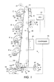
- the electrophotographic printing machine of the present invention uses a charge retentive surface in the form of an Active Matrix (AMAT) photoreceptor belt 10 supported for movement in the direction indicated by arrow 12, for advancing sequentially through the various xerographic process stations.
- the belt is entrained about a drive roller 14 and tension and steering rollers 16 and 18 respectively, roller 14 is operatively connected to a drive motor 20 for effecting movement of the belt through the xerographic stations.
- AMAT Active Matrix
- a portion of belt 10 passes through charging station A where a corona generating device, indicated generally by the reference numeral 22, charges the photoconductive surface of belt 10 to a relative high, substantially uniform, preferably negative potential.
- the charged portion of photoconductive surface is advanced through an imaging station B.
- the uniformly charged belt 10 is exposed to a laser based output scanning device 24 which causes the charge retentive surface to be discharged in accordance with the output from the scanning device.
- the scanning device is a laser Raster Output Scanner (ROS).
- ROS Raster Output Scanner
- the ROS could be replaced by other xerographic exposure devices such as LED arrays.
- the photoreceptor which is initially charged to a voltage V c , undergoes dark decay to a level V ddp equal to about -500 volts. When exposed at the exposure station B it is discharged to V image equal to about -50 volts. Thus after exposure, the photoreceptor contains a monopolar voltage profile of high and low voltages, the former corresponding to charged areas and the latter corresponding to discharged or image areas.
- developer structure indicated generally by the reference numeral 32 utilizing a hybrid jumping development (HJD) system
- the development roll better known as the donor roll
- the first field is the AC jumping field which is used for toner cloud generation.
- the second field is the DC development field which is used to control the amount of developed toner mass on the photoreceptor.
- the toner cloud causes charged toner particles 26 to be attracted to the electrostatic latent image. Appropriate developer biasing is accomplished via a power supply.
- This type of system is a noncontact type in which only toner particles (magenta, for example) are attracted to the latent image and there is no mechanical contact between the photoreceptor and a toner delivery device to disturb a previously developed, but unfixed, image.
- toner particles magenta, for example
- the developed but unfixed image is then transported past a second charging device 36 where the photoreceptor and previously developed toner image areas are recharged to a predetermined level.
- a second exposure/imaging is performed by imaging device 38 which comprises a laser based output structure and is utilized for selectively discharging the photoreceptor on toned areas and/or bare areas, pursuant to the image to be developed with the second color toner.
- the photoreceptor contains toned and untoned areas at relatively high voltage levels and toned and untoned areas at relatively low voltage levels. These low voltage areas represent image areas which are developed using discharged area development (DAD).
- DAD discharged area development
- a negatively charged, developer material 40 comprising color toner is employed.
- the toner which by way of example may be yellow, is contained in a developer housing structure 42 disposed at a second developer station D and is presented to the latent images on the photoreceptor by way of a second HSD developer system.
- a power supply (not shown) serves to electrically bias the developer structure to a level effective to develop the discharged image areas with negatively charged yellow toner particles 40.
- a negative pretransfer dicorotron member 50 is provided to condition the toner for effective transfer to a substrate using positive corona discharge.
- a sheet of support material 52 is moved into contact with the toner images at transfer station G.
- the sheet of support material is advanced to transfer station G by a sheet feeding apparatus to the pretransfer device which directs the advancing sheet of support material into contact with photoconductive surface of belt 10 in a timed sequence so that the toner powder image developed thereon contacts the advancing sheet of support material at transfer station G.
- Transfer station G includes a transfer dicorotron 54 which sprays positive ions onto the backside of sheet 52. This attracts the negatively charged toner powder images from the belt 10 to sheet 52.
- a detack dicorotron 56 is provided for facilitating stripping of the sheets from the belt 10.
- Fusing station H includes a fuser assembly, indicated generally by the reference numeral 60, which permanently affixes the transferred powder image to sheet 52.
- fuser assembly 60 comprises a heated fuser roller 62 and a backup or pressure roller 64.
- Sheet 52 passes between fuser roller 62 and backup roller 64 with the toner powder image contacting fuser roller 62. In this manner, the toner powder images are permanently affixed to sheet 52 after it is allowed to cool.
- the sheet is separated from the fuser roll by the corrugating air knife, described in more detail below, to a chute, not shown, which guides the advancing sheets 52 to a catch tray, not shown, for subsequent removal from the printing machine by the operator.
- the residual toner particles carried by the non-image areas on the photoconductive surface are removed therefrom. These particles are removed at cleaning station I using a cleaning brush structure contained in a housing 66.
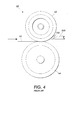
- a sheet 52 passes between the heated roll 62 and the pressure roll 64 causing the toner image thereon to be fused to the sheet.
- an air knife 300 provide a stream of air to assist in separating the fused sheet from the heated fuser roll.
- the air blast from the air knife on a light weight sheet would cause the lead edge of the sheet to fold over while the imaged area "retacked" to the fuser roll 62. This would cause the sheet to wrap around the fuser roll 62 causing a jam as opposed to exiting through the sheet guide.
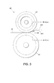
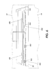
- the corrugating air knife 400 utilizes a manifold 401 which directs stream of air across the width of the sheet but further has extra ribs 402 formed which have a air passage integral to the rib 402 as shown in Fig 5.
- the localized stream of air which flows from the ribs 402 causes a lightweight sheet to corrugate due to the air stream which increases the beam strength of the sheet and prevents the lead edge of the sheet 152 from folding over and wrapping around the fuser.
- the control for the air stream is modified to enhance the stripping effect of the air knife.
- a short burst of air was used to separate the lead edge of the sheet from the fuser roll and the air was then discontinued.
- this single burst of air did not prevent retack and wrap jams.
- the solution is to provide an initial burst of air utilizing the localized air jets 402 and then to continue the airstream at a lesser pressure to continue to assist in the separation of the sheet from the fuser. This continued air stream has the additional benefit of cooling the lighter weight sheets to help reduce the chance of hot offset or other damage to the image due to the image not being fully cooled.
- Heavier weight sheets do not absorb as much heat nor is the beam strength such that wrap jams are a problem so the air knife can be used less or even not at all depending of the sheet weight.
- the control for the air knife can be predetermined based on the sheet weight requested for a particular job or by sensing the weight of the sheet as it is processed in the machine and automatically adjusting the air knife in response to the sheet weight.
- a multifunction air knife for stripping a sheet from a fusing member.
- the air knife includes a manifold connected to an air supply source and has an outlet which directs a flow of air across a sheet path adjacent the fuser. The airflow is controlled so that for lighter weight sheets there is an initial burst of air and then a lesser continuous stream to prevent the light sheets from retacking to the fuser member.
Landscapes
- Physics & Mathematics (AREA)
- General Physics & Mathematics (AREA)
- Color Electrophotography (AREA)
- Control Or Security For Electrophotography (AREA)
- Treatment Of Fiber Materials (AREA)
- Preliminary Treatment Of Fibers (AREA)
Abstract
Description
Claims (5)
- A multifunction air knife, comprising:a manifold connected to an air supply source, wherein said manifold defines an outlet for providing a directed stream of air from said manifold;an air source control to vary an air pressure supplied to the manifold in response to a predetermined condition.
- An air knife according to claim 1, wherein said air source control varies the air pressure between two distinct states, a first state being a relatively high pressure and a second state being a lower pressure.
- An air knife according to claim 1, wherein said predetermined condition is determined based upon the weight of a sheet.
- A device for fusing a toner image to a sheet comprising:a heated fusing roll;a pressure roll in circumferential contact with said heated fusing roll to form a nip therebetween;a manifold, adjacent said the nip formed by said heated fusing roll and said pressure roll, said manifold connected to an air supply source, wherein said manifold defines an outlet for providing a directed stream of air from said manifold;an air source control to vary an air pressure supplied to the manifold in response to a predetermined condition.
- An electrophotographic printing machine having a fusing apparatus, comprising:a print engine for forming and depositing a toner image on a substrate;a heated fusing roll;a pressure roll in circumferential contact with said heated fusing roll to form a nip therebetween;a manifold, adjacent said the nip formed by said heated fusing roll and said pressure roll, said manifold connected to an air supply source, wherein said manifold defines an outlet for providing a directed stream of air from said manifold;an air source control to vary an air pressure supplied to the manifold in response to a predetermined condition.
Applications Claiming Priority (4)
| Application Number | Priority Date | Filing Date | Title |
|---|---|---|---|
| US31507901P | 2001-08-27 | 2001-08-27 | |
| US315079P | 2001-08-27 | ||
| US10/043,206 US20030039491A1 (en) | 2001-08-27 | 2002-01-14 | Multi-function air knife |
| US43206 | 2002-01-14 |
Publications (2)
| Publication Number | Publication Date |
|---|---|
| EP1288736A2 true EP1288736A2 (en) | 2003-03-05 |
| EP1288736A3 EP1288736A3 (en) | 2004-05-19 |
Family
ID=26720142
Family Applications (1)
| Application Number | Title | Priority Date | Filing Date |
|---|---|---|---|
| EP02255905A Withdrawn EP1288736A3 (en) | 2001-08-27 | 2002-08-23 | Multi-function air knife |
Country Status (2)
| Country | Link |
|---|---|
| US (1) | US20030039491A1 (en) |
| EP (1) | EP1288736A3 (en) |
Cited By (3)
| Publication number | Priority date | Publication date | Assignee | Title |
|---|---|---|---|---|
| EP1959315A1 (en) | 2007-02-13 | 2008-08-20 | Xerox Corporation | Air knife system with pressure sensor |
| EP2146254A1 (en) | 2008-06-09 | 2010-01-20 | Xerox Corporation | Printing machine and method of operating printing machine |
| EP2388658A3 (en) * | 2010-05-17 | 2014-05-14 | Konica Minolta Business Technologies, Inc. | Fixing device and image forming apparatus |
Families Citing this family (14)
| Publication number | Priority date | Publication date | Assignee | Title |
|---|---|---|---|---|
| US20030049042A1 (en) * | 2001-08-27 | 2003-03-13 | Xerox Corporation | Corrugating air knife |
| US7742732B2 (en) * | 2005-12-09 | 2010-06-22 | Xerox Corporation | Fuser arranged for reduced pressure member speed, and an image forming device including the same |
| US7280793B2 (en) | 2005-12-09 | 2007-10-09 | Xerox Corporation | Fuser arranged for braking and an image forming device including the same |
| US7751767B2 (en) | 2006-09-07 | 2010-07-06 | Xerox Corporation | Rotatable air knife |
| US8086158B2 (en) * | 2007-06-27 | 2011-12-27 | Xerox Corporation | Method and apparatus for enhanced sheet stripping |
| US20090178298A1 (en) * | 2008-01-15 | 2009-07-16 | Anatoli Anatolyevich Abramov | Device for fluid removal after laser scoring |
| US20100158545A1 (en) * | 2008-12-19 | 2010-06-24 | Eastman Kodak Company | Electophotographic borderless printing method and apparatus |
| US8280297B2 (en) * | 2008-12-19 | 2012-10-02 | Eastman Kodak Company | Electophotographic borderless printing method and apparatus |
| US8408270B2 (en) * | 2009-10-07 | 2013-04-02 | Xerox Corporation | Apparatuses useful in printing, fixing devices and methods of stripping substrates from surfaces in apparatuses useful in printing |
| US8380118B2 (en) * | 2010-08-30 | 2013-02-19 | Xerox Corporation | Apparatus and method for stripper finger operation |
| JP5590003B2 (en) * | 2011-10-21 | 2014-09-17 | コニカミノルタ株式会社 | Image forming apparatus |
| JP6104027B2 (en) * | 2013-04-17 | 2017-03-29 | キヤノン株式会社 | Fixing device |
| JP6413527B2 (en) * | 2014-09-11 | 2018-10-31 | コニカミノルタ株式会社 | Image forming apparatus |
| JP6601247B2 (en) * | 2016-02-09 | 2019-11-06 | コニカミノルタ株式会社 | Image forming apparatus, image forming system, and air blowing control method |
Family Cites Families (6)
| Publication number | Priority date | Publication date | Assignee | Title |
|---|---|---|---|---|
| JPS5494340A (en) * | 1978-01-09 | 1979-07-26 | Ricoh Co Ltd | Paper separator |
| JPS5940672A (en) * | 1982-08-31 | 1984-03-06 | Canon Inc | Separation device in image forming equipment |
| JPS6162087A (en) * | 1984-09-03 | 1986-03-29 | Fuji Xerox Co Ltd | Paper peeling device of fuser roll |
| JPH0381791A (en) * | 1989-08-25 | 1991-04-08 | Hitachi Koki Co Ltd | Paper peeling device for electrophotographic device |
| US5356127A (en) * | 1992-12-01 | 1994-10-18 | Xerox Corporation | Self adjusting vacuum corrugated feeder and method of feeding a sheet |
| JP2002091223A (en) * | 2000-09-18 | 2002-03-27 | Fuji Xerox Co Ltd | Image forming device and fixing device |
-
2002
- 2002-01-14 US US10/043,206 patent/US20030039491A1/en not_active Abandoned
- 2002-08-23 EP EP02255905A patent/EP1288736A3/en not_active Withdrawn
Cited By (5)
| Publication number | Priority date | Publication date | Assignee | Title |
|---|---|---|---|---|
| EP1959315A1 (en) | 2007-02-13 | 2008-08-20 | Xerox Corporation | Air knife system with pressure sensor |
| US7505723B2 (en) | 2007-02-13 | 2009-03-17 | Xerox Corporation | Air knife system with pressure sensor |
| EP2146254A1 (en) | 2008-06-09 | 2010-01-20 | Xerox Corporation | Printing machine and method of operating printing machine |
| US7965969B2 (en) | 2008-06-09 | 2011-06-21 | Xerox Corporation | Active rotation of air knife for increased performance |
| EP2388658A3 (en) * | 2010-05-17 | 2014-05-14 | Konica Minolta Business Technologies, Inc. | Fixing device and image forming apparatus |
Also Published As
| Publication number | Publication date |
|---|---|
| US20030039491A1 (en) | 2003-02-27 |
| EP1288736A3 (en) | 2004-05-19 |
Similar Documents
| Publication | Publication Date | Title |
|---|---|---|
| US20030039491A1 (en) | Multi-function air knife | |
| US5850589A (en) | Sheet moisture replacement system using water jet technology | |
| EP0905574B1 (en) | Controlled moisturization of paper to eliminate curl | |
| US6055409A (en) | Sheet pre-transfer device | |
| US6606478B2 (en) | Composite transfer assist blade | |
| US5987301A (en) | Paper conditioning system | |
| US7720401B2 (en) | Inter-document zone gloss defect eliminator | |
| EP1291736A2 (en) | Air knife for corrugating paper sheets | |
| US6823166B2 (en) | Image bearing apparatus that collects image bearing bodies at a common place | |
| US5895154A (en) | Textured rollers for paper conditioning | |
| US5543908A (en) | Image forming apparatus having endless recording material carrying member | |
| US6539194B2 (en) | Image forming apparatus including transfer belt having first and second image transfer surface planes arranged at an angle, and plural image bearing members facing same | |
| US7751767B2 (en) | Rotatable air knife | |
| JP3346063B2 (en) | Image transfer device | |
| US5930578A (en) | Moisturizing rolls with end grooves for eliminating water spill from their ends | |
| JP4350240B2 (en) | Electrophotographic printing machine | |
| EP0469911B1 (en) | Method of transferring a toner image from a flexible member to a copy medium | |
| EP1130481B1 (en) | Conditioner rolls end seals | |
| US7123860B1 (en) | Small footprint charge device for tandem color marking engines | |
| US8422933B2 (en) | Curved pre-fuser transport to enable larger sheets through a xerographic print engine | |
| JPH06301296A (en) | Exfoliation of paper from photosensitive- body belt at low stress | |
| US6574450B2 (en) | Sheet pre-transfer device | |
| JP2024119740A (en) | Image forming system and static elimination device | |
| JP2797288B2 (en) | Multicolor image forming device | |
| JP3431794B2 (en) | Image forming device |
Legal Events
| Date | Code | Title | Description |
|---|---|---|---|
| PUAI | Public reference made under article 153(3) epc to a published international application that has entered the european phase |
Free format text: ORIGINAL CODE: 0009012 |
|
| AK | Designated contracting states |
Kind code of ref document: A2 Designated state(s): AT BE BG CH CY CZ DE DK EE ES FI FR GB GR IE IT LI LU MC NL PT SE SK TR Designated state(s): AT BE BG CH CY CZ DE DK EE ES FI FR GB GR IE IT LI LU MC NL PT SE SK TR |
|
| AX | Request for extension of the european patent |
Extension state: AL LT LV MK RO SI |
|
| PUAL | Search report despatched |
Free format text: ORIGINAL CODE: 0009013 |
|
| AK | Designated contracting states |
Kind code of ref document: A3 Designated state(s): AT BE BG CH CY CZ DE DK EE ES FI FR GB GR IE IT LI LU MC NL PT SE SK TR |
|
| AX | Request for extension of the european patent |
Extension state: AL LT LV MK RO SI |
|
| RIC1 | Information provided on ipc code assigned before grant |
Ipc: 7B 65H 29/54 B Ipc: 7G 03G 15/00 B Ipc: 7G 03G 15/20 A |
|
| 17P | Request for examination filed |
Effective date: 20041119 |
|
| AKX | Designation fees paid |
Designated state(s): DE FR GB |
|
| 17Q | First examination report despatched |
Effective date: 20050316 |
|
| STAA | Information on the status of an ep patent application or granted ep patent |
Free format text: STATUS: THE APPLICATION IS DEEMED TO BE WITHDRAWN |
|
| 18D | Application deemed to be withdrawn |
Effective date: 20050727 |