EP1288686A2 - Optical transmission system - Google Patents
Optical transmission system Download PDFInfo
- Publication number
- EP1288686A2 EP1288686A2 EP02090304A EP02090304A EP1288686A2 EP 1288686 A2 EP1288686 A2 EP 1288686A2 EP 02090304 A EP02090304 A EP 02090304A EP 02090304 A EP02090304 A EP 02090304A EP 1288686 A2 EP1288686 A2 EP 1288686A2
- Authority
- EP
- European Patent Office
- Prior art keywords
- input
- output
- laser beam
- optical
- distance
- Prior art date
- Legal status (The legal status is an assumption and is not a legal conclusion. Google has not performed a legal analysis and makes no representation as to the accuracy of the status listed.)
- Withdrawn
Links
Images



Classifications
-
- G—PHYSICS
- G02—OPTICS
- G02B—OPTICAL ELEMENTS, SYSTEMS OR APPARATUS
- G02B6/00—Light guides; Structural details of arrangements comprising light guides and other optical elements, e.g. couplings
- G02B6/24—Coupling light guides
- G02B6/26—Optical coupling means
- G02B6/35—Optical coupling means having switching means
- G02B6/351—Optical coupling means having switching means involving stationary waveguides with moving interposed optical elements
- G02B6/3512—Optical coupling means having switching means involving stationary waveguides with moving interposed optical elements the optical element being reflective, e.g. mirror
-
- G—PHYSICS
- G02—OPTICS
- G02B—OPTICAL ELEMENTS, SYSTEMS OR APPARATUS
- G02B6/00—Light guides; Structural details of arrangements comprising light guides and other optical elements, e.g. couplings
- G02B6/24—Coupling light guides
- G02B6/26—Optical coupling means
- G02B6/35—Optical coupling means having switching means
- G02B6/354—Switching arrangements, i.e. number of input/output ports and interconnection types
- G02B6/3554—3D constellations, i.e. with switching elements and switched beams located in a volume
- G02B6/3556—NxM switch, i.e. regular arrays of switches elements of matrix type constellation
Definitions
- the present invention relates to an optical transmission system that causes a light beam to propagate through a space and more particularly to an optical transmission system of the type needing high signal quality.
- Japanese Patent Laid-Open Publication No. 6-75176 discloses a microdynamic optical switch including an input port implemented by a single optical fiber, a mirror for steering a light beam, a piezoelectric actuator for moving the mirror, and an output port implemented by n optical fibers.
- the input port and output port are inclined by 90° relative to each other.
- a light beam output from the input port is incident to the output port via the mirror, which is inclined by 45° relative to an optical path assigned to the light beam.
- the distance between the input port and the output port is greater than 50 ⁇ m if optics include a collimator lens or 50 ⁇ m or below if otherwise.
- the distance of 50 ⁇ m or below is, according to the above document, necessary for achieving a small insertion loss.
- the document describes that the collimator lens collimates the light beam to thereby reduce the divergence of the light beam, realizing a small insertion loss even if the distance is greater than 50 ⁇ m.
- the piezoelectric actuator taught in the above document and having a micromechanical structure cannot drive the mirror by more than a certain distance, limiting the number of input ports and output ports available. Further, the distance between the input port and the mirror and therefore the beam radius differs in dependence on the output port. This means that signal quality is dependent on the output port.
- Japanese Patent Laid-Open Publication No. 2000-10029 proposes an optical switch including an input port and an output port implemented by optical fibers, a plurality of lenses, a plurality of movable mirrors, and a fixed mirror.
- This document describes that the movable mirrors operate in this manner to minimize an optical loss.
- Such an optical switch needs movable mirrors and requires them to move over a broad range while increasing a distance between the input port and the output port.
- the increase in the distance between the input port and the output port causes the distance between the input port and the mirrors to vary in dependence on the output port, also causing signal quality to vary in dependence on the output port.
- An optical transmission system of the present invention includes a plurality of input ports to which a plurality of laser beams input respectively.
- a plurality of input optical elements corresponding one-to-one to the input ports each condense a particular laser beam.
- a plurality of input reflectors corresponding one-to-one to the input optical elements each reflecting a particular condensed laser beam.
- a plurality of output reflectors each further reflect the particular laser beam.
- a plurality of output optical elements corresponding one-to-one to the output reflectors each further condense the respective reflected laser beam.
- a plurality of output ports corresponding one-to-one to the output optical elements each receive the respective condensed laser beam.
- the beam radius of the laser beam at the output end of the input port, the wavelength of the laser beam, the distance between the output end and the input optical element and the focal distance of the input optical element are selected such that the beam waist position Q of the laser beam output from the input optical element closest to the input port satisfies the relation: 0.9(DL + DS) /4 ⁇ Q ⁇ 1.1(DL + DS)/4
- a laser beam can be dealt with as a Gaussian beam and has the following characteristics. As shown in FIG. 1, when a Gaussian beam is condensed by an optical element, typically a lens, 1, its radius becomes minimum at a position spaced from the optical element 1 by a preselected distance. Such a position is generally referred to as a beam waist position. Also, a beam radius, as measured at the beam waist position, where power is 1/e 2 of power at the center of the beam is referred to as a beam waist radius.
- Wo is the beam waist radius at the beam waist position
- ⁇ is the wavelength of the beam
- x is a distance from the beam waist position
- ⁇ is the ratio of the circumference of a circle to its diameter.
- FIG. 2 shows a relation between the distance from the beam waist position and the beam radius.
- the ordinate indicates the beam radius W(x) ( ⁇ m) while the abscissa indicates the distance x (nm) from the beam waist position; the position on the abscissa where the distance x is zero is the beam waist position.
- Curves shown in FIG. 2 were derived from a wavelength ⁇ of 1.55 ⁇ m and various beam waist radiuses by using the Eq. (1).
- the beam broadens as the distance from the beam waist position increases.
- the lower limit of the beam radius at such a distance is theoretically determined.
- FIG. 3 shows a specific optical transmission system including two optical elements and two reflectors.
- a beam input via an input port, not shown is incident to an input optical element 2.
- the input optical element 2 condenses the incident beam onto an input reflector 4.
- the input reflector 4 steers the beam by reflecting it although the beam is shown as propagating straight in FIG. 3. This is also true with the beam incident to an output reflector 5.
- the beam steered by the input reflector 4 still maintains the characteristics given by the input optical element 2. It follows that the beam radius decreases with the propagation of the beam and becomes minimum at the beam waist position. Subsequently, the beam radius increases with an increase in the distance from the beam waist position.
- the beam is then incident to the output reflector 5 and again steered thereby before reaching an output optical element 3.
- the output optical element 3 condenses the incident beam onto an output port not shown.
- the optical transmission system shown in FIG. 3 includes a plurality of pairs of input ports and input optical elements 2 and a plurality of pairs of output ports and output optical elements 3. Then, the distance between the input optical element 2 and the output optical element 3 varies in accordance with the combination of the input port and output port. When the above distance varies, the ratio of the beam radius on each of the reflectors 4 and 5 to the size of the reflector also varies.
- FIG. 4 shows a relation between the optical loss (ordinate) and the ratio of the circular mirror radius to the beam radius (abscissa). As shown, the optical loss increases with a decrease in the ratio of the mirror radius to the beam radius. Such a variation of the optical loss causes signal quality to vary from one output port to another output port, as stated earlier. Therefore, if the ratio of the size of the reflector 4 or 5 to the beam radius is confined in a certain range without regard to the variation of the distance between the two optical elements 2 and 3, then there can be achieved an optical transmission system free from the above problem.
- the ratio of the mirror radius to the beam radius is 1.6 or above
- the optical loss is zero, so that increasing the ratio above 1.6 is meaningless. Radiuses above 1.6 simply make the circular mirror large more than necessary and therefore make an optical switch bulky while reducing the number of input ports and that of output ports available.
- ratios to 0.9 maintain the optical loss less than 1 dB and are therefore desirable in practice.
- ratios to 0.6 maintain the optical loss less than 3 dB and are acceptable in practice. Therefore, the ratio should preferably be 0.6 or above, more preferably 0.9 or above, but 1.6 or below.
- a reflector closest to an input port (corresponding to the input reflector 4) and a reflector closest to an output port (corresponding to the output reflector) each are provided with the following size.
- each reflector is selected to be the size of a circle whose radius is 0.6 times as great as the value derived from the Eq. (2) or above, preferably 0.9 times as great as the same value or above, but 1. 6 times or below.
- the output port when the output port is switched, the optical distance between the input optical element 2 and the output optical element 3 varies. Consequently, the output reflector 5 is shifted relative to the beam waist position with the result that the beam radius at the position of the reflector 5 varies, causing the optical loss to vary.
- a change in optical loss directly translates into a change in signal quality. It is therefore necessary to reduce the variation of the optical loss. This is also true when the output port is switched. In this manner, the variation of the optical loss is ascribable to the variation of the optical distance between the input port and the output port that are switched.
- the influence of the variation of the optical distance can be minimized if the variation of the distance between the beam waist position and each reflector is minimized.
- the beam waist position is dependent on, e.g., the beam radius at a light source or the input port, not shown, the distance between the light source or the input port and the input optical element 2 or the focal distance of the optical element 2, i.e., dependent mainly on the characteristic of the optical element 2.
- Such a characteristic of the optical element 2 can be determined independently of the optical distance between the beam waist position and the output port.
- the beam waist position should only be located at the center of the width over which the optical distance between the input port and the output port varies.
- the distances DL and DS between the optical element closest to the input port and the optical element closest to the output port can be geometrically determined.
- the beam waist position can also be determined by use of general geometric optical calculation.
- the beam waist position Q is acceptable even when it varies within the range of 10 % of (DL + DS)/4, i.e.: 0.9 x (DL + DS)/4 ⁇ Q ⁇ 1.1 X (DS + DS)/4
- DL is equal to DS, so that the beam waist position is located at the intermediate between the input port and the output port.
- the beam waist position Q may be located at any position within the variation width of the optical distance between the input port and the output port for the same reason as described above, i.e.: DS/2 ⁇ Q ⁇ DL/2
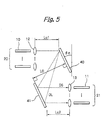
- the optical transmission system includes an input port 20, a plurality of input optical elements 12, a group of input reflectors 40, a group of output reflectors 41, a plurality of output optical elements 13, and an output port 21.
- the input port 20 and output port 21 include a plurality of single-mode optical fibers 10 and a plurality of single-mode optical fibers 11, respectively. More specifically, at the input port 20, 1,296 single-mode optical fibers are arranged in a 36 (vertical) x 36 (horizontal) lattice configuration at a pitch of 1.0 mm. A laser beam having a wavelength of 1.55 ⁇ m is radiated toward the input optical element 12 via the individual optical fiber 10.
- the input optical elements 12, which are condenser lenses, are each implemented as a convex lens formed of synthetic quartz and having a focal distance of 3.50 mm.
- the optical elements 12 are arranged in a 36 (vertical) x 36 (horizontal) lattice configuration at a pitch of 1.0 mm in the same manner as the optical fibers 10 of the input port 20.
- the output end of each optical fiber 10 and the corresponding optical element 12 are spaced by a distance of 3.60 mm.
- the laser beam output from any one of the optical fibers 10 is transmitted through preselected one of the optical element 12 toward the group of input reflectors 40.
- the input reflectors constituting the group 40 are implemented as an assembly of mirrors.
- micromirrors 101 are formed on a ceramic substrate 100 and mainly formed of silicon.
- the micromirrors 101 are also arranged in a 36 (vertical) x 36 (horizontal) lattice configuration at a pitch of 1.00 mm vertically and a pitch of 1.10 mm horizontally.
- the micromirrors 101 can be inclined by the maximum angle of 10° in both of the vertical and horizontal directions.
- Each micromirror 101 has a circular configuration having a radius of 0.3 mm. While the reflectors each are implemented as a circle in the illustrative embodiment, they may be implemented as a polygon contacting the circle, e.g., a square whose one side is 0.6 mm long.
- a controller controls the inclination of the micromirrors 101, which are the input reflectors or the output reflectors. Preselected one of the micromirrors 101 reflects the laser beam transmitted through any one of the input optical elements 12. The laser beam reflected by the micromirror 101 is incident to preselected one of the output reflectors 41.
- the input reflectors 40 are inclined by the angle ⁇ m of 25° toward the input optical elements 12, as stated earlier.
- the minimum distance Lu 1 between the input optical elements 12 and the input reflectors 40 is 31.00 mm while the vertical distance L 0 between the input reflectors 40 and the output reflectors 41 is 100.00 mm.
- the output reflectors 41 are identical in arrangement as the input reflectors 40 and inclined toward the output optical elements 13 by an angle ⁇ m of 25°.
- the output reflectors 41 face the input reflectors 40 in parallel to the input reflectors 40 so as to receive the laser beam output from the input reflectors 40.
- the laser beam reflected by any one of the input reflectors 40 is incident to preselected one of the micromirrors 101 constituting the output reflectors 41.
- the controller controls the inclination of the output reflectors 41, i.e., micromirrors 101 also.
- the laser beam reflected by the micromirror 101 is incident to preselected one of the output optical elements 11 constituting the output port 21.
- the output optical elements 13 are identical in structure with the input optical elements 12.
- the distance between the output ends of the optical fibers 11 and the output optical elements 13 is selected to be 3.60 mm.
- the laser beam again reflected by any one of the output reflectors 41 is incident to preselected one of the optical fibers 11 via the one of the output optical element 13.
- the minimum distance Lu 2 between the output optical elements 13 and the reflectors 41 is selected to be 31.00 mm.
- the laser beam with the wavelength of 1.55 ⁇ m is output via any one of the optical fibers 10 of the input port 20.
- the output end of each optical fiber 10 constitutes one beam waist position.
- the laser beam output from the optical fiber 10 is incident to the corresponding input optical element 12 while broadening itself.
- the input optical element 12 condenses the incident laser beam toward corresponding one of the input reflectors 40, i.e., micromirrors 101.
- the controller controls the angle of the mirror surfaces of the micromirrors 101 such that the laser beam reflected by the above micromirror 101 is steered toward preselected one of the output reflectors 41.
- the controller controls the angle of the mirror surfaces of the output reflectors 41, i.e., micromirrors 101 such that the laser beam output from the input reflector 40 is incident to corresponding one of the output reflectors 41, i.e., micromirrors 101.
- the micromirror 101 reflects the incident laser beam toward associated one of the output optical elements 13.
- the output optical element 13 condenses the laser beam toward preselected one of the optical fibers 11 constituting the output port 21. This completes the switching operation.
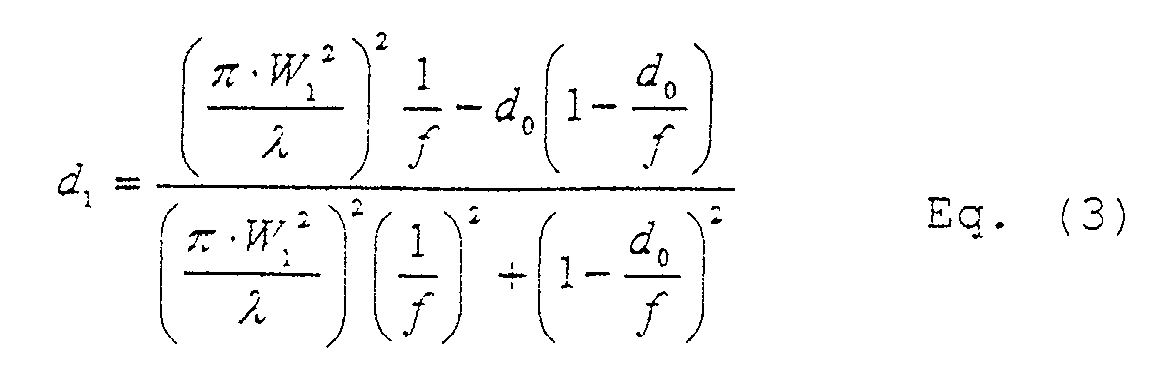
- the beam waist position i.e., the distance d 1 between each input optical element 12 and the beam waist position is expressed as: where W 1 is the radius of the core of each optical fiber 10 at the input side, ⁇ is the wavelength of the laser beam, d 0 is the distance between the output end of each optical fiber 10 and the corresponding input optical element 12, and f is the focal distance of the input optical element 12.
- the distance between the output ends of the optical fibers 10 and the input optical elements 12 is 3.60 mm, each input optical element 12 has a focal distance of 3.5 mm, the wavelength is 1.55 ⁇ m, and the core radius of each optical fiber 10 is 5 ⁇ m, as stated earlier. Therefore, the beam waist position d 1 is 100.97 mm as produced by the Eq. (3).
- the minimum optical distance DS and the maximum optical distance DL are 192.91 mm and 205.35 mm, respectively, so that (DL + DS)/4 is 99.6 mm.
- the beam waist position d 1 is therefore 0.9 (DL + DS)/4 or above, but 1.1 (DL + DS)/4 or below, which is the prerequisite.
- the beam waist position d 1 is DS/2 or above, but DS/2 or below. It follows that the input reflectors (micromirrors) and output reflectors can both be reduced in size in good balance. This allows the input reflectors and output reflectors and therefore the entire optical transmission system to be reduced in size.
- the distance between the beam waist position and the input reflector 40 closest to the input side i.e., (d 1 - Lu 1 ) is 69.97 mm.
- the distance between the beam waist position and the output reflector 40 closest to the output side i.e., (DL - Lu 2 - d 1 ) is 73.38 mm.
- the distances from the beam waist position do not exceed such distances. That is, such a distance is the maximum distance between the input reflectors 40 and the output reflectors 41.
- the beam waist radius W 2 at the beam waist position is determined in accordance with the Eq. (4).
- the maximum beam radius on the input reflectors 40 is determined to be 0.280 mm.
- W 2 is substituted for W 0 while 73.38 mm is substituted for x , producing the maximum beam radius of 0.271 mm on the output reflectors 40.
- each micromirror 101 has a circular configuration with a radius of 0.3 mm, it is 0.9 times (0.252 mm) as great as the maximum beam radius (0.271 mm) of the output reflectors 40 or above, but 1.6 times (0.448 mm) or below, which is the prerequisite. This implements an optical loss of less than 1 dB throughout the input reflectors and output reflectors (micromirrors), thereby insuring the same high signal quality over the entire output port.
- the maximum and minimum optical power losses between the input and the output were 5.2 dB and 4.42 dB, respectively.
- the optical power loss is therefore 6 dB or below, as expected, and fully acceptable in practice.
- the difference between the maximum optical power loss and the minimum optical power loss was as small as 0.78 dB smaller than 1 dB. Such a difference means that signal quality is little susceptible to the switching operation and therefore desirable.
- the present invention provides an optical transmission system capable of preventing signal quality from differing in dependence on the output port and therefore insuring uniform, high signal quality.
Landscapes
- Physics & Mathematics (AREA)
- General Physics & Mathematics (AREA)
- Optics & Photonics (AREA)
- Mechanical Light Control Or Optical Switches (AREA)
- Optical Communication System (AREA)
Abstract
Description
Claims (4)
- An optical transmission system comprising:wherein, assuming that a maximum optical distance and a minimum optical distance between the input optical element closest to the input port and the output optical element closest to the output port are DL and DS, respectively, a beam radius of the laser beam at an output end of said input port, a wavelength of said laser beam, a distance between said output end and said input optical element and a focal distance of said input optical element are selected such that a beam waist position Q of said laser beam output from said input optical element closest to said input port satisfies a relation:a plurality of input ports to which a plurality of laser beams are respectively input;a plurality of input optical elements corresponding one-to-one to said plurality of input ports each for condensing a particular laser beam;a plurality of input reflectors corresponding one-to-one to said plurality of input optical elements each for reflecting a particular condensed laser beam;a plurality of output reflectors each for further reflecting a particular laser beam;a plurality of output optical elements corresponding one-to-one to said plurality of output reflectors each for further condensing the reflected laser beam; anda plurality of output ports corresponding one-to-one to said plurality of output optical elements each for receiving the condensed laser beam;
- An optical transmission system comprising:wherein assuming that a maximum optical distance and a minimum optical distance between the input optical element closest to the input port and the output optical element closest to the output port are DL and DS, respectively, a beam radius of the laser beam at an output end of said input port, a wavelength of said laser beam, a distance between said output end and said input optical element and a focal distance of said input optical element are selected such that a beam waist position Q of said laser beam output from said input optical element closest to said input port satisfies a relation:a plurality of input ports to which a plurality of laser beams are respectively input;a plurality of input optical elements corresponding one-to-one to said plurality of ports each for condensing a particular laser beam;a plurality of input reflectors corresponding one-to-one to said plurality of input optical elements each for reflecting a particular condensed laser beam;a plurality of output reflectors each for further reflecting the laser beam;a plurality of output optical elements corresponding one-to-one to said plurality of output reflectors each for further condensing the reflected laser beam; anda plurality of output ports corresponding one-to-one to said plurality of output optical elements each for receiving the condensed laser beam;
- The system as claimed in claim 1 or 2, wherein the input reflector closest to the input port has a circular configuration whose radius R has the following relation or a configuration containing said circular configuration:
there is a relation: - The system as claimed in claim 3, wherein said reflector closest to said output port has a circular configuration having the followingradius or a configuration containing said circular configuration:
Applications Claiming Priority (2)
| Application Number | Priority Date | Filing Date | Title |
|---|---|---|---|
| JP2001258703 | 2001-08-28 | ||
| JP2001258703A JP2003066348A (en) | 2001-08-28 | 2001-08-28 | Optical transmission system |
Publications (2)
| Publication Number | Publication Date |
|---|---|
| EP1288686A2 true EP1288686A2 (en) | 2003-03-05 |
| EP1288686A3 EP1288686A3 (en) | 2004-05-26 |
Family
ID=19086174
Family Applications (1)
| Application Number | Title | Priority Date | Filing Date |
|---|---|---|---|
| EP02090304A Withdrawn EP1288686A3 (en) | 2001-08-28 | 2002-08-27 | Optical transmission system |
Country Status (4)
| Country | Link |
|---|---|
| US (1) | US7095962B2 (en) |
| EP (1) | EP1288686A3 (en) |
| JP (1) | JP2003066348A (en) |
| CN (1) | CN1402445A (en) |
Families Citing this family (3)
| Publication number | Priority date | Publication date | Assignee | Title |
|---|---|---|---|---|
| US7697115B2 (en) * | 2006-06-23 | 2010-04-13 | Asml Holding N.V. | Resonant scanning mirror |
| US8224189B1 (en) | 2007-02-02 | 2012-07-17 | Sunlight Photonics Inc. | Retro-directive target for free-space optical communication and method of producing the same |
| WO2018236664A1 (en) * | 2017-06-20 | 2018-12-27 | Boston Scientific Scimed, Inc. | LASER SYSTEMS AND METHODS |
Family Cites Families (11)
| Publication number | Priority date | Publication date | Assignee | Title |
|---|---|---|---|---|
| US5208880A (en) | 1992-04-30 | 1993-05-04 | General Electric Company | Microdynamical fiber-optic switch and method of switching using same |
| JPH112769A (en) | 1997-06-13 | 1999-01-06 | Seiko Epson Corp | Optical scanning device |
| JPH1195154A (en) | 1997-09-16 | 1999-04-09 | Oki Electric Ind Co Ltd | Optical lens device for free space optical network and its production |
| JPH1190665A (en) | 1997-09-25 | 1999-04-06 | Mitsubishi Electric Corp | Laser processing equipment |
| US6295154B1 (en) | 1998-06-05 | 2001-09-25 | Texas Instruments Incorporated | Optical switching apparatus |
| US6445841B1 (en) * | 1999-05-28 | 2002-09-03 | Omm, Inc. | Optomechanical matrix switches including collimator arrays |
| EP1102096B1 (en) | 1999-11-17 | 2005-03-23 | Lucent Technologies Inc. | Optical crossconnect using tilting mirror MEMS array |
| US6253001B1 (en) * | 2000-01-20 | 2001-06-26 | Agilent Technologies, Inc. | Optical switches using dual axis micromirrors |
| JP2001305376A (en) * | 2000-02-17 | 2001-10-31 | Nippon Sheet Glass Co Ltd | Method for designing collimator array device and collimator array device manufactured by the method |
| US6363182B2 (en) * | 2000-07-31 | 2002-03-26 | James D. Mills | Optical switch for reciprocal traffic |
| US6493139B1 (en) * | 2001-03-16 | 2002-12-10 | Hongdu Liu | Optical switch |
-
2001
- 2001-08-28 JP JP2001258703A patent/JP2003066348A/en active Pending
-
2002
- 2002-08-27 EP EP02090304A patent/EP1288686A3/en not_active Withdrawn
- 2002-08-27 US US10/228,057 patent/US7095962B2/en not_active Expired - Fee Related
- 2002-08-28 CN CN02142145.5A patent/CN1402445A/en active Pending
Also Published As
| Publication number | Publication date |
|---|---|
| US7095962B2 (en) | 2006-08-22 |
| US20030048515A1 (en) | 2003-03-13 |
| CN1402445A (en) | 2003-03-12 |
| EP1288686A3 (en) | 2004-05-26 |
| JP2003066348A (en) | 2003-03-05 |
Similar Documents
| Publication | Publication Date | Title |
|---|---|---|
| EP1291690B1 (en) | Optical switch with converging element | |
| US20220244360A1 (en) | Hybrid two-dimensional steering lidar | |
| US7982957B2 (en) | Optical apparatus using a lens array | |
| US6415067B1 (en) | N x M optical switch | |
| EP1331709A1 (en) | Laser diode collimating system | |
| US11394461B2 (en) | Free space optical communication terminal with actuator system and optical relay system | |
| US6483961B1 (en) | Dual refraction index collimator for an optical switch | |
| JP2002055276A (en) | Fine aspherical collimator lens | |
| WO1997042533A1 (en) | High efficiency fiber optic coupler that reduces beam divergence | |
| US9326050B2 (en) | Wavelength selective switch and method of manufacturing same | |
| US6687428B2 (en) | Optical switch | |
| JP5935465B2 (en) | Optical device | |
| US8310766B2 (en) | Two-dimensional lensing arrangment for optical beam collimation and beam orientation | |
| JPH11101923A (en) | Optical fiber wavelength multiplexer-demultiplexer | |
| US6832859B1 (en) | Free space optical system with multiple function detectors | |
| US7095962B2 (en) | Optical transmission system | |
| US6253005B1 (en) | Apparatus and method for compensating for misalignment in reflective packages | |
| CA2355918C (en) | M x n optical matrix switch | |
| US6400512B1 (en) | Refractive/reflective optical element multiple beam spacer | |
| US6219473B1 (en) | Optical fiber wavelength multiplexer-demultiplexer | |
| EP1223456B1 (en) | Low polarisation dependent loss beam splitter | |
| JP2002107566A (en) | Optical functional module | |
| US7181102B1 (en) | Optical switching systems and methods | |
| US6407867B1 (en) | Multiple beam spacer with a beam splitter cube and two roof mirrors | |
| EP0602832B1 (en) | Methods and apparatus for combining arrays of light beams |
Legal Events
| Date | Code | Title | Description |
|---|---|---|---|
| PUAI | Public reference made under article 153(3) epc to a published international application that has entered the european phase |
Free format text: ORIGINAL CODE: 0009012 |
|
| AK | Designated contracting states |
Kind code of ref document: A2 Designated state(s): AT BE BG CH CY CZ DE DK EE ES FI FR GB GR IE IT LI LU MC NL PT SE SK TR Designated state(s): AT BE BG CH CY CZ DE DK EE ES FI FR GB GR IE IT LI LU MC NL PT SE SK TR |
|
| AX | Request for extension of the european patent |
Extension state: AL LT LV MK RO SI |
|
| PUAL | Search report despatched |
Free format text: ORIGINAL CODE: 0009013 |
|
| AK | Designated contracting states |
Kind code of ref document: A3 Designated state(s): AT BE BG CH CY CZ DE DK EE ES FI FR GB GR IE IT LI LU MC NL PT SE SK TR |
|
| AX | Request for extension of the european patent |
Extension state: AL LT LV MK RO SI |
|
| 17P | Request for examination filed |
Effective date: 20040803 |
|
| 17Q | First examination report despatched |
Effective date: 20041103 |
|
| AKX | Designation fees paid |
Designated state(s): DE FR GB |
|
| STAA | Information on the status of an ep patent application or granted ep patent |
Free format text: STATUS: THE APPLICATION IS DEEMED TO BE WITHDRAWN |
|
| 18D | Application deemed to be withdrawn |
Effective date: 20050315 |