EP1288673A2 - Mobile Navigationsvorrichtung für ein zellulares Funknetz - Google Patents
Mobile Navigationsvorrichtung für ein zellulares Funknetz Download PDFInfo
- Publication number
- EP1288673A2 EP1288673A2 EP02019018A EP02019018A EP1288673A2 EP 1288673 A2 EP1288673 A2 EP 1288673A2 EP 02019018 A EP02019018 A EP 02019018A EP 02019018 A EP02019018 A EP 02019018A EP 1288673 A2 EP1288673 A2 EP 1288673A2
- Authority
- EP
- European Patent Office
- Prior art keywords
- navigation device
- base station
- mobile navigation
- building
- radio
- Prior art date
- Legal status (The legal status is an assumption and is not a legal conclusion. Google has not performed a legal analysis and makes no representation as to the accuracy of the status listed.)
- Granted
Links
Images
Classifications
-
- H—ELECTRICITY
- H04—ELECTRIC COMMUNICATION TECHNIQUE
- H04W—WIRELESS COMMUNICATION NETWORKS
- H04W64/00—Locating users or terminals or network equipment for network management purposes, e.g. mobility management
-
- G—PHYSICS
- G01—MEASURING; TESTING
- G01S—RADIO DIRECTION-FINDING; RADIO NAVIGATION; DETERMINING DISTANCE OR VELOCITY BY USE OF RADIO WAVES; LOCATING OR PRESENCE-DETECTING BY USE OF THE REFLECTION OR RERADIATION OF RADIO WAVES; ANALOGOUS ARRANGEMENTS USING OTHER WAVES
- G01S5/00—Position-fixing by co-ordinating two or more direction or position line determinations; Position-fixing by co-ordinating two or more distance determinations
- G01S5/02—Position-fixing by co-ordinating two or more direction or position line determinations; Position-fixing by co-ordinating two or more distance determinations using radio waves
- G01S5/0252—Radio frequency fingerprinting
- G01S5/02521—Radio frequency fingerprinting using a radio-map
-
- G—PHYSICS
- G01—MEASURING; TESTING
- G01C—MEASURING DISTANCES, LEVELS OR BEARINGS; SURVEYING; NAVIGATION; GYROSCOPIC INSTRUMENTS; PHOTOGRAMMETRY OR VIDEOGRAMMETRY
- G01C21/00—Navigation; Navigational instruments not provided for in groups G01C1/00 - G01C19/00
- G01C21/20—Instruments for performing navigational calculations
- G01C21/206—Instruments for performing navigational calculations specially adapted for indoor navigation
-
- G—PHYSICS
- G01—MEASURING; TESTING
- G01S—RADIO DIRECTION-FINDING; RADIO NAVIGATION; DETERMINING DISTANCE OR VELOCITY BY USE OF RADIO WAVES; LOCATING OR PRESENCE-DETECTING BY USE OF THE REFLECTION OR RERADIATION OF RADIO WAVES; ANALOGOUS ARRANGEMENTS USING OTHER WAVES
- G01S5/00—Position-fixing by co-ordinating two or more direction or position line determinations; Position-fixing by co-ordinating two or more distance determinations
- G01S5/02—Position-fixing by co-ordinating two or more direction or position line determinations; Position-fixing by co-ordinating two or more distance determinations using radio waves
- G01S5/14—Determining absolute distances from a plurality of spaced points of known location
Definitions
- the present invention relates to accessory systems for cellular radio networks and especially on a mobile one Navigation device for a cellular radio network.
- the navigation in buildings includes support a mobile subscriber, such as B. a robot, a person, a vehicle, etc. regarding the Orientation, pathfinding and other localization-based Actions in a building.
- RSSI Radio Signal Strength Indicator
- a disadvantage of these systems is the fact that in particular the entire problem in the field strength measurement the transmission channel, the multiple reflections, in particular is present in buildings etc., so that an exact position can be determined only under idealized conditions sufficient accuracy is possible. In real scenarios, such as B. a larger building, an airport, etc. the positioning is therefore very imprecise, especially if a variety of base stations and other radio subscribers is available.
- U.S. Patent No. 5,208,756 discloses a vehicle positioning and navigation system that in conjunction with a cellular telephone network works. A little hidden one Device is placed in a vehicle and is by activated a special signal from a telephone station. After activation, the device determines the power with the normally transmitted control channels from several base stations of the network can be received. Then the device calculates the distance between the vehicle and several base stations, to then use triangulation techniques or arculation method the position of the vehicle to be determined and transmitted back to the telephone station, from which the activation signal was received.
- DE 197 03 916 A1 discloses a method for prediction the building attenuation with radio signals, with knowledge the width and floor height of the building practical for the damping of the building can be determined at any location on different floors is.
- predicting radio field attenuation within of the building is initially the building attenuation in Ground floor of the building determined. Then be aware the type of electromagnetic wave propagation and The respective radio field attenuation at each location of any floor of the building can be determined.
- U.S. Patent No. 5,657,487 discloses a navigation assistant for handling calls in mobile phone systems. Using information from base stations can be obtained, the mobile station is able to change its distance from each base station based on a middle one Approximate signal strength to give a rough sector position to determine. Information from the base station are also used by the mobile station to reduce the propagation loss for transmission to the base station and the appropriate power level and timing Determine control for transmissions to the base station.
- the object of the present invention is a mobile navigation device for a cellular radio network to create that can be easily integrated into the cellular radio network is and enables an exact position determination.
- This task is accomplished through a mobile navigation device according to claim 1 and by a method of delivery solved by navigation data according to claim 19.
- the present invention is based on the finding that that the concept of field strength measurement in contrast to Runtime determination as with GPS especially in buildings due to the higher accuracy that can be achieved in principle well suited.
- Building existing transmission link complexity includes a mobile navigation device according to the invention Device for calculating a distance of the mobile navigation device one or more base stations, wherein the means for calculating the distance is arranged is both a radio characteristic of a base station as well as a channel model to take into account the transmission properties for the radio signal in an environment the base station describes.
- cellular radio systems exist not just information about a position Base station, but information also exists about the environment of the base station, which is responsible for the transmission properties are relevant.
- Such information is according to the invention considered and included in a channel model for example the strength of one in the vicinity of the Base station arranged wall or ceiling of the building, distances the base station to ceilings, walls or floors, Propagation parameters of the materials used for the Radio signal, etc.
- the radio characteristic is also the base station takes into account, this Radio characteristics, for example an antenna diagram of the Base station and the transmission field strength of the base station are taken into account. Due to the field strength measurement, the transmit field strength and the antenna characteristics of the transmitting antenna the base station and that through the mobile navigation device measured reception field strength can then with high Accuracy of the distance of the mobile navigation device to the sending base station.
- a base station that is easily identified using the base station can be determined, exploited, but any amount of other information about the transmission properties of radio signals in the building in which navigation information should be determined.
- This Information can be determined and the mobile navigation device provided before a positioning action become.
- An advantage of the mobile navigation device according to the invention is that it can work purely passively, which means that they are only normal operating signals of the Must receive base stations of a cellular radio network, however, no own transmission signals for position determination must send out.
- the cellular radio network need not have the presence of a Navigation device to be informed. This attribute leads to the fact that the mobile navigation device is very flexible can be used and without registration, registration etc. can be distributed to users.
- Another advantage of the mobile navigation device according to the invention is that they have no runtime measurements gets along and on the basis of the reception field strength using the environmental information provided regarding the characteristics of the radio channel and the characteristics of the transmitter, d. H. a base station, enables precise position determination.
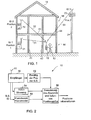
- Fig. 1 shows a building scenario in which an inventive mobile navigation device 10 by a user 12 is held, can be used.
- a building 14 with a ground floor 16 and a first Floor 18 shown.
- the first base station 21 is located on the ground floor 16 of the building.
- the second base station 22 is on the first floor of the building arranged while the third base station 23 outside of building 14, e.g. B. placed on a transmission tower 24 is.
- the position of each base station is fixed.
- Each base station also includes its own base station identification (ID1, ID2 or ID3). Between the mobile Navigation device 10 and the transmission antenna of each base station there is a transmission channel 31, 32 or 33, which is shown in dashed lines in Fig. 1.
- the transmission channels 31, 32 and 33 differ due to the nature of the building and especially the Floor plan of building 14 as follows.
- the transmission channel 31 from the first base station 21 to the mobile one Navigation device comprises two inner walls 41, 42 of the Building 14.
- the transmission channel 32 from the second base station 22 to the mobile navigation device 10 includes on the other hand, in addition to the two inner walls, the ceiling 43 between the upper floor 18 and the first floor 16 of the Building.
- the transmission channel 33 from the third base station 23 extends to the mobile navigation device contrast, by the ceiling 43 and additionally by a Exterior wall 44 of the building.
- the blanket, Interior walls and exterior walls made of different materials constructed what different damping properties for radio signals.
- exterior walls and ceilings be made of reinforced concrete, which has a high damping supplies for electromagnetic waves while interior walls especially in office buildings mostly made of dry construction materials exist, which only a low damping for electromagnetic waves.
- base stations 1 and 2 in particular be designed, mainly the particular one Floor, which is why the transmitting antennas of the base stations 21 and 22 should have a strong directivity, while the base station 3 is intended to the space 14 surrounding the building as evenly as possible "sweep" so that this antenna has a weak directional characteristic should have and is more intended to have a radiation diagram that is as round as possible.
- the base station should reach corresponding ranges 3 equipped with a higher transmission field strength his. According to the invention, this information is used to determine the position used as explained below becomes.
- the mobile navigation device includes a receiver 50 for receiving an over an antenna 51 received radio signal.
- the radio signal comes from a base station and typically contains the base station identification number, which of this base station is permanently assigned.
- the base station identification is determined by a device 52 the specified position of the base station.
- the Device 52 could, for example, have a stored table in which every base station to be expected Location coordinates or information about the position the base station, e.g. B. Room 7 in the second Floor, attached to the outer wall, can include. By simple table access can be provided by the device 52 in this If so, determine the position of the base station.
- the mobile navigation device 10 comprises also a device 54 for measuring the electrical Field strength of the radio signal received by antenna 51.
- the field strength values of the radio signal and the position of the base station are a device 56 for calculating a distance of the mobile navigation device fed from the base station to use the same the position of the base station information about provide the position of the mobile navigation device can.
- the device 56 preferably has access to information about a stored in a memory 58 Radio characteristics of a base station concerned and on information for a channel model that has transmission properties for the radio signal in an environment of the base station describes.
- the mobile navigation device There is only one active base station in the cellular radio network, that is the mobile navigation device already able to roughly approximate the position to achieve that only a certain sector exists in which radio signals from the base station exist can be received. This happens because of the base station identification (ID) and thus connected position of the base station.
- ID base station identification
- the invention mobile navigation device already one calculate rough distance.
- the navigation device according to the invention can then z. B. two different Channel models that e.g. B. take into account that either a single inner wall or two inner walls between the receiver 10 and the transmitter 21, determine in which room on the ground floor the mobile navigation device is arranged.
- the mobile receiver receives signals from several base stations, their position and characteristics as well as their different channel models 31-33 (Fig. 1) of the mobile navigation device are known is an even more precise position determination possible.
- Using the radio characteristics from Z. B. three base stations and using different channel models again with the number of Inner walls or a ceiling or outer wall as parameters in The position can be linked to a plausibility check the mobile navigation device is already essential can be determined more precisely.
- 1 receives radio signals from Base stations 21-23, so it first becomes the base station identifications determine and then, based on the Base station identifications the radio characteristics of the find out three base stations from which it receives radio signals.
- the recipient could then, for example, for the base station is based on a channel model that only includes an inner wall.
- base station 2 could he used a duct model that was just an inner wall and includes a blanket. This would mean that the mobile navigation device in the middle room of the ground floor 16 of the building 14 of FIG. 1 would.
- the received signal of the base station 2 in Compared to the signal from base station 1 identified as too weak would be assumed for the sake of illustration, that this difference is not yet at the plausibility limit fails.
- the navigation device When evaluating the signal from the base station 3, however, the navigation device find that the received field strength for a model an outer wall, an inner wall and a ceiling, the would apply if the mobile navigation device would be located in the middle room of the ground floor is strong. A plausibility check therefore becomes Result come out that the mobile navigation device cannot be located in the middle room on the ground floor. Using the building's floor plan information the next step is therefore a channel model situation in which the user, as in FIG. 1 drawn, located in the right room of the ground floor 16. Here the mobile navigation device becomes a sensible one plausible match of the three received signals from the determine three base stations, so that a distance evaluation and subsequent positioning, for example by triangulation processes can.
- the mobile navigation device in addition the receiver system 50 for acquiring the base station identification and RSSI data collection to bring them all together Time receivable signals from individual base stations to include a so-called RSSI smoothing unit in device 56 which contains the measured RSSI values algorithmic using the base station parameters, mathematical channel models, floor plan data of the building and by evaluating parameterized environmental data of the building corrected.
- a so-called RSSI smoothing unit in device 56 which contains the measured RSSI values algorithmic using the base station parameters, mathematical channel models, floor plan data of the building and by evaluating parameterized environmental data of the building corrected.
- the mobile navigation device is preferably in one portable terminal, d. H. a PDA, a cell phone, a notebook, a clock, etc. to position the positioning algorithms, the navigation functionality and preferably an output in the form of speech or graphics of the Provide results and help for a user the mobile navigation device further comprising a Has input interface so the user special Can direct questions to the mobile navigation device.
- the means 56 for calculating further comprises a module, the distances from the preferably optimized RSSI measured values to calculate.
- the mobile navigation device preferably further comprises a positioning module, which is adapted by using recursive and heuristic procedures, such as B. using a Kalman filter, one continuously Carries out position calculation.
- a positioning module which is adapted by using recursive and heuristic procedures, such as B. using a Kalman filter, one continuously Carries out position calculation.
- An optimization module which is based on logical evaluations the floor plan data and the resulting plausibility checks of the building works, contributes to one further optimization of those determined in the positioning module Position at.
- another Be provided module which by using the optimized position of the user by a user requested assistance is generated and sent to the user in Outputs language, graphic etc.
- the mobile navigation device can thereby be added that for the required environmental data own infrastructure of Reference transmitters, sensors and other external information sources provided.
- This additional infrastructure can be used the mobile navigation device constantly update to an adaptive Operation of the navigation device in different environments to enable.
- the adaptivity is then on the one hand useful when changes are made to a building.
- adaptivity is essential when the mobile navigation device is universal for different Environments should be used. It will be like this at some point lack memory resources when environmental data or channel models for not just a single airport, but are fed in for several airports or hotels should.
- the adaptive functionality also allows when in one and the same system is used, an even more precise one Determining the distance of the mobile navigation device from different base stations and thus leads to an increase in the stability of the system and the positional accuracy.
- At least two antennas on the mobile navigation device it is also preferred to have at least two antennas on the mobile navigation device to install through the achieved antenna diversity compared to multipath propagation or constructive and destructive interference less sensitive to be what is also in a more precise and more reliable determination of the RSSI values result becomes.
- the mobile navigation device can also be a compass to be supplemented by the spatial orientation of the user to improve.
- additional inertial sensor system for example with Speed or acceleration sensors, used, which are based on special applications, e.g. B. running, driving, etc., are adapted, so this also enables an optimized Determination of position and orientation.
- Speed or acceleration sensors used, which are based on special applications, e.g. B. running, driving, etc., are adapted, so this also enables an optimized Determination of position and orientation.
- the "on-board" sensor system also provides navigation when in there is insufficient radio field strength in a building due to, for example, destructive interference. In such a case, your own navigation system be used. So it doesn't have to be in every case navigation by means of a telephone signal. In order to the overall accuracy of the system can be improved.
- a receiver for a cellular Radio system such as B. the DECT system or a To provide DECT derivative, but also for other systems, such as B. WLAN, Bluetooth.
- B. the DECT system or a To provide DECT derivative but also for other systems, such as B. WLAN, Bluetooth.
- This can cover the area of the navigation system and the accuracy of the position determination be improved.
- This functionality enables it further a user, his mobile navigation device not only to be used in a DECT system, but also in any other systems, which is special should be advantageous for travelers.
- the concept according to the invention is also characterized by its parameterizability using channel models, Base station information or environment information as a parameter, from and is to different environments adaptable or dynamically reloadable on site.
- the concept according to the invention can be particularly favorable in synchronism Networks such as B.
- a cellular DECT network can be used as RSSI values differ Base stations can be measured almost simultaneously because a DECT frame comprises only 10 ms, in which 10 Send all base stations to ms-Frame.
- An exact position determination is in such a synchronous network therefore also for a mobile navigation device moving relatively quickly possible.
- the temporal resolution of the mobile navigation device is in synchronous networks therefore particularly good since the fixed relationship of the transmission properties of the base stations can be used to each other can.
- the mobile navigation device can e.g. B. in a PDA be accommodated. This comes with a DECT-PCMCIA plug-in card extended. This allows the DECT module the base stations and the associated RSSI values determined become.
- a driver software can then all other Devices shown in Fig. 2 in connection realize with the processor of the PDA, and can also provide a visualization interface on which on request Position data can be made available. As The driver software uses input parameters for information about the base stations, the environment and other configuration data. So there is a management or information system that the mobile communication device according to of the present invention, which is inexpensive is flexible in use and provides precise information.
Landscapes
- Engineering & Computer Science (AREA)
- Radar, Positioning & Navigation (AREA)
- Remote Sensing (AREA)
- Physics & Mathematics (AREA)
- General Physics & Mathematics (AREA)
- Automation & Control Theory (AREA)
- Computer Networks & Wireless Communication (AREA)
- Signal Processing (AREA)
- Mobile Radio Communication Systems (AREA)
- Position Fixing By Use Of Radio Waves (AREA)
- Fittings On The Vehicle Exterior For Carrying Loads, And Devices For Holding Or Mounting Articles (AREA)
- Telephone Function (AREA)
Abstract
Description
- Fig. 1
- ein Gebäudeszenario, in dem die mobile Navigationsvorrichtung gemäß der vorliegenden Erfindung einsetzbar ist; und
- Fig. 2
- ein Blockdiagramm einer erfindungsgemäßen mobilen Navigationsvorrichtung.
Claims (19)
- Mobile Navigationsvorrichtung für ein zellulares Funknetz, das in und/oder um ein Gebäude (14) herum angeordnet ist und zumindest eine Basisstation (21, 22, 23) mit einer Basisstation-Identifikation (ID1, ID2, ID3) aufweist, wobei die Basisstation an einer vorgegebenen Position angeordnet ist, mit folgenden Merkmalen:wobei die Einrichtung (56) zum Berechnen des Abstandes ausgebildet ist, um eine Funkcharakteristik der Basisstation, Informationen über einen Grundriß des Gebäudes und eine Mehrzahl von Kanalmodellen (58), die Übertragungseigenschaften für das Funksignal in einer Umgebung der Basisstation für unterschiedliche Positionen der mobilen Navigationsvorrichtung bezüglich des durch den Grundriß definierten Gebäudes beschreiben, bei der Berechnung des Abstandes zu berücksichtigen, undeinem Empfänger (50) zum Empfangen eines Funksignals mit einer elektrischen Feldstärke, das die Basisstations-Identifikation aufweist;einer Einrichtung (52) zum Ermitteln der vorgegebenen Position der Basisstation aufgrund der Basisstations-Identifikation;einer Einrichtung (54) zum Messen der Feldstärke des Funksignals;einer Einrichtung (56) zum Berechnen eines Abstandes der mobilen Navigationsvorrichtung von der Basisstation, um unter Verwendung der vorgegebenen Position der Basisstation Informationen über die Position der mobilen Navigationsvorrichtung zu erhalten,
wobei die Einrichtung (56) zum Berechnen des Abstandes ferner ausgebildet ist, um unter Verwendung eines ersten Kanalmodells der Mehrzahl von Kanalmodellen eine erste Position bezüglich des Gebäudes zu bestimmen, um unter Verwendung eines zweiten Kanalmodells der Mehrzahl von Kanalmodellen eine zweite Position bezüglich des Gebäudes zu bestimmen, und um aufgrund einer Plausibilitätsüberprüfung der ersten und der zweiten Position einen Raum bezüglich der Grundrisses des Gebäudes zu bestimmen, in dem sich die mobile Navigationsvorrichtung befindet. - Mobile Navigationsvorrichtung nach Anspruch 1, bei der die Mehrzahl von Kanalmodellen (58) Ausbreitungseigenschaften für das Funksignal in einem Material berücksichtigen, das das Gebäude aufweist.
- Mobile Navigationsvorrichtung nach Anspruch 1 oder 2, bei der das zellulare Funknetz eine Mehrzahl von Basisstationen (21, 22, 23) aufweist, wobei jede Basisstation an einer vorgegebenen Position angeordnet ist und eine eigene Basisstations-Identifikation aufweist, und
wobei die mobile Navigationsvorrichtung ferner einen Speicher aufweist, in dem die vorgegebene Position der Basisstation in Zuordnung zu der Basisstations-Identifikation jeder Basisstation gespeichert ist, und bei der die Einrichtung (56) zum Berechnen angeordnet ist, um unter Verwendung von Funksignalen der Mehrzahl von Basisstationen Ortskoordinaten der Navigationsvorrichtung zu berechnen. - Mobile Navigationsvorrichtung nach einem der vorhergehenden Ansprüche,
bei der die Funkcharakteristik (58) ein Antennendiagramm und eine Sendefeldstärke der Basisstation aufweist. - Mobile Navigationsvorrichtung nach einem der vorhergehenden Ansprüche,
bei der das zellulare Funknetz ein synchrones Funknetz ist, bei dem vorhandene Basisstationen in einer festen Beziehung hinsichtlich der Zeit und/oder der Frequenz zueinander stehen, und
bei der der Empfänger (50) angeordnet ist, um in Kenntnis der festen Beziehung Funksignale der Basisstationen zu empfangen. - Mobile Navigationsvorrichtung nach Anspruch 5, bei der das zellulare Funknetz ein Funknetz gemäß dem DECT-Standard oder einem Derivat desselben ist.
- Mobile Navigationsvorrichtung nach einem der Ansprüche 2 bis 6,
bei der die Mehrzahl von Kanalmodellen parametrisiert sind, wobei ein Parameter eine Anzahl und/oder ein Material von Innenwänden des Gebäudes ist. - Mobile Navigationsvorrichtung nach einem der vorhergehenden Ansprüche,
die ferner ein Positionierungsmodul aufweist, das unter Verwendung von rekursiven und/oder heuristischen Verfahren eine kontinuierliche Positionsberechnung durchführt. - Mobile Navigationsvorrichtung nach Anspruch 8, bei der das Positionierungsmodul ein Kalman-Filter aufweist.
- Mobile Navigationsvorrichtung nach einem der Ansprüche 2 bis 9, die ferner ein Optimierungsmodul aufweist, das angeordnet ist, um unter Verwendung der Grundrißdaten des Gebäudes (14) eine Plausibilitätsüberprüfung der Informationen über die Position der mobilen Navigationsvorrichtung durchzuführen.
- Mobile Navigationsvorrichtung nach einem der vorhergehenden Ansprüche, die ferner eine Schnittstelle für einen Benutzer aufweist, um unter Verwendung der Informationen über die Position der mobilen Navigationsvorrichtung Hilfsinformationen für den Benutzer zu erzeugen und auszugeben.
- Mobile Navigationsvorrichtung nach einem der vorhergehenden Ansprüche,
bei der der Empfänger (50) eine Mehrzahl von Antennen aufweist, und
bei der die Einrichtung (56) zum Berechnen des Abstandes angeordnet ist, um über die Mehrzahl von Antennen empfangene Funksignale derselben Basisstation zu verwenden. - Mobile Navigationsvorrichtung nach einem der vorhergehenden Ansprüche,
bei der das zellulare Funknetz angeordnet ist, um über zumindest einen Referenzsender der mobilen Navigationsvorrichtung Informationen über eine Funkstrecke von einer Basisstation zu der Navigationsvorrichtung zur Verfügung zu stellen, und
bei der der Empfänger (50) angeordnet ist, um die Informationen zu empfangen, und
bei der die Einrichtung (56) zum Berechnen die Informationen berücksichtigt. - Mobile Navigationsvorrichtung nach einem der vorhergehenden Ansprüche, die ferner einen Beschleunigungssensor aufweist, und
bei der die Einrichtung zum Berechnen (56) angeordnet ist, um bei den Informationen über die Position ein Ausgangssignal des Beschleunigungssensors zu berücksichtigen. - Mobile Navigationsvorrichtung nach einem der vorhergehenden Ansprüche,
die ferner einen Kompaß aufweist. - Mobile Navigationsvorrichtung nach einem der vorhergehenden Ansprüche,
bei der der Empfänger (50) angeordnet ist, um Funksignale von zumindest zwei zellularen Funknetzen, die nach einer unterschiedlichen Spezifikation arbeiten, zu empfangen. - Mobile Navigationsvorrichtung nach einem der vorhergehenden Ansprüche, die angeordnet ist, um rein passiv ohne Aussendung eigener Funksignale zu arbeiten.
- Mobile Navigationsvorrichtung nach einem der vorhergehenden Ansprüche, wobei die Funkcharakteristik der Basisstation und die Kanalmodelle in der mobilen Navigationsvorrichtung gespeichert sind oder mittels einer Datenübertragungsschnittstelle adaptiv zur Verfügung gestellt werden.
- Verfahren zum Liefern von Navigationsinformationen in einem zellularen Funknetz, das in und/oder um ein Gebäude (14) herum angeordnet ist und das zumindest eine Basisstation (21, 22, 23) mit einer Basisstation-Identifikation (ID1, ID2, ID3) aufweist, wobei die Basisstation an einer vorgegebenen Position angeordnet ist, mit folgenden Schritten:wobei eine Funkcharakteristik der Basisstation, Informationen über einen Grundriß des Gebäudes und eine Mehrzahl von Kanalmodellen, die Übertragungseigenschaften für das Funksignal in einer Umgebung der Basisstation für unterschiedliche Positionen der mobilen Navigationsvorrichtung bezüglich des durch den Grundriß definierten Gebäudes beschreiben, im Schritt des Berechnens des Abstandes berücksichtigt werden, wobei die Funkcharakteristik der Basisstation und das Kanalmodell vorgegeben sind, undEmpfangen (50) eines Funksignals mit einer elektrischen Feldstärke, das die Basisstations-Identifikation aufweist;Ermitteln (52) der vorgegebenen Position der Basisstation aufgrund der Basisstations-Identifikation;Messen (54) der Feldstärke des Funksignals;Berechnen (56) eines Abstandes der mobilen Navigationsvorrichtung von der Basisstation, um unter Verwendung der vorgegebenen Position der Basisstation Informationen über die Position der mobilen Navigationsvorrichtung zu erhalten,
wobei im Schritt des Berechnens unter Verwendung eines ersten Kanalmodells der Mehrzahl von Kanalmodellen eine erste Position bezüglich des Gebäudes bestimmt wird, wobei unter Verwendung eines zweiten Kanalmodells der Mehrzahl von Kanalmodellen eine zweite Position bezüglich des Gebäudes bestimmt wird, und wobei aufgrund einer Plausibilitätsüberprüfung der ersten und der zweiten Position ein Raum bezüglich der Grundrisses des Gebäudes bestimmt wird, in dem sich die mobile Navigationsvorrichtung befindet.
Applications Claiming Priority (2)
| Application Number | Priority Date | Filing Date | Title |
|---|---|---|---|
| DE10142156A DE10142156B4 (de) | 2001-08-29 | 2001-08-29 | Mobile Navigationsvorrichtung für ein zellulares Funknetz sowie Verfahren zum Liefern von Navigationsinformationen |
| DE10142156 | 2001-08-29 |
Publications (3)
| Publication Number | Publication Date |
|---|---|
| EP1288673A2 true EP1288673A2 (de) | 2003-03-05 |
| EP1288673A3 EP1288673A3 (de) | 2005-08-03 |
| EP1288673B1 EP1288673B1 (de) | 2007-03-21 |
Family
ID=7696879
Family Applications (1)
| Application Number | Title | Priority Date | Filing Date |
|---|---|---|---|
| EP02019018A Expired - Lifetime EP1288673B1 (de) | 2001-08-29 | 2002-08-26 | Mobile Navigationsvorrichtung für ein zellulares Funknetz |
Country Status (6)
| Country | Link |
|---|---|
| EP (1) | EP1288673B1 (de) |
| AT (1) | ATE357672T1 (de) |
| DE (2) | DE10142156B4 (de) |
| DK (1) | DK1288673T3 (de) |
| ES (1) | ES2281481T3 (de) |
| PT (1) | PT1288673E (de) |
Cited By (5)
| Publication number | Priority date | Publication date | Assignee | Title |
|---|---|---|---|---|
| WO2004098941A1 (en) * | 2003-05-07 | 2004-11-18 | Dawson, Nicole | Accelerator pedal signal controller |
| FR2866774A1 (fr) * | 2004-02-23 | 2005-08-26 | France Telecom | Procede et dispositif de localisation d'un terminal dans un reseau local sans fil |
| EP1762113A4 (de) * | 2004-06-30 | 2012-09-05 | Sk Planet Co Ltd | Verfahren zur bereitstellung eines warndienstes nach bewegung ausserhalb einer sicherheitszone |
| CN116685920A (zh) * | 2020-11-12 | 2023-09-01 | 奥地利西门子公司 | 用于对生产设施的数据进行无线电传输的方法和系统 |
| CN120454906A (zh) * | 2025-05-29 | 2025-08-08 | 北京邮电大学 | 环境特征辅助的信道多径智能预测方法及装置 |
Families Citing this family (3)
| Publication number | Priority date | Publication date | Assignee | Title |
|---|---|---|---|---|
| DE102005026788A1 (de) * | 2005-06-10 | 2006-12-21 | Deutsche Telekom Ag | Verfahren und System zur Lokalisierung eines mobilen WLAN-Clients |
| DE102011011528B4 (de) | 2011-02-17 | 2018-04-26 | Johannes Feuchter | System und Verfahren zur Bestimmung zumindest einer Höhenposition innerhalb eines Gebäudes |
| DE102016200010A1 (de) * | 2016-01-04 | 2017-07-06 | Siemens Schweiz Ag | Kalibrierung der Position von mobilen Objekten in Gebäuden |
Family Cites Families (7)
| Publication number | Priority date | Publication date | Assignee | Title |
|---|---|---|---|---|
| US5208756A (en) * | 1991-01-28 | 1993-05-04 | Song Han L | Vehicle locating and navigating system |
| US5404376A (en) * | 1993-09-09 | 1995-04-04 | Ericsson-Ge Mobile Communications Inc. | Navigation assistance for call handling in mobile telephone systems |
| US5613205A (en) * | 1995-03-31 | 1997-03-18 | Telefonaktiebolaget Lm Ericsson | System and method of locating a mobile terminal within the service area of a cellular telecommunication system |
| US5657487A (en) * | 1995-06-05 | 1997-08-12 | Airnet Communications Corporation | Mobile telephone location process making use of handoff data |
| GB2329801B (en) * | 1996-03-22 | 1999-07-28 | Matsushita Electric Industrial Co Ltd | System for detection of position of radio mobile station |
| DE19703916C2 (de) * | 1997-02-03 | 2001-05-23 | Deutsche Telekom Mobil | Verfahren zur Prädiktion der Gebäudedämpfung bei Funksignalen |
| EP1109031A1 (de) * | 1999-12-10 | 2001-06-20 | Ascom Systec AG | Verfahren und Einrichtung zum Lokalisieren eines mobilen Terminals |
-
2001
- 2001-08-29 DE DE10142156A patent/DE10142156B4/de not_active Expired - Fee Related
-
2002
- 2002-08-26 EP EP02019018A patent/EP1288673B1/de not_active Expired - Lifetime
- 2002-08-26 PT PT02019018T patent/PT1288673E/pt unknown
- 2002-08-26 DE DE50209751T patent/DE50209751D1/de not_active Expired - Lifetime
- 2002-08-26 ES ES02019018T patent/ES2281481T3/es not_active Expired - Lifetime
- 2002-08-26 AT AT02019018T patent/ATE357672T1/de active
- 2002-08-26 DK DK02019018T patent/DK1288673T3/da active
Cited By (6)
| Publication number | Priority date | Publication date | Assignee | Title |
|---|---|---|---|---|
| WO2004098941A1 (en) * | 2003-05-07 | 2004-11-18 | Dawson, Nicole | Accelerator pedal signal controller |
| FR2866774A1 (fr) * | 2004-02-23 | 2005-08-26 | France Telecom | Procede et dispositif de localisation d'un terminal dans un reseau local sans fil |
| EP1575328A1 (de) * | 2004-02-23 | 2005-09-14 | France Telecom | Verfahren und Vorrichtung zur Lokalisierung eines Endgerätes in einem drahtlosen LAN |
| EP1762113A4 (de) * | 2004-06-30 | 2012-09-05 | Sk Planet Co Ltd | Verfahren zur bereitstellung eines warndienstes nach bewegung ausserhalb einer sicherheitszone |
| CN116685920A (zh) * | 2020-11-12 | 2023-09-01 | 奥地利西门子公司 | 用于对生产设施的数据进行无线电传输的方法和系统 |
| CN120454906A (zh) * | 2025-05-29 | 2025-08-08 | 北京邮电大学 | 环境特征辅助的信道多径智能预测方法及装置 |
Also Published As
| Publication number | Publication date |
|---|---|
| PT1288673E (pt) | 2007-04-30 |
| EP1288673A3 (de) | 2005-08-03 |
| DK1288673T3 (da) | 2007-06-25 |
| DE10142156B4 (de) | 2006-01-19 |
| ATE357672T1 (de) | 2007-04-15 |
| DE50209751D1 (de) | 2007-05-03 |
| EP1288673B1 (de) | 2007-03-21 |
| ES2281481T3 (es) | 2007-10-01 |
| DE10142156A1 (de) | 2003-04-03 |
Similar Documents
| Publication | Publication Date | Title |
|---|---|---|
| DE102004035531B4 (de) | Vorrichtung und Verfahren zum Ermitteln einer aktuellen Position eines mobilen Gerätes | |
| EP2999973B1 (de) | Mobiles tragbares gerät und positionsbestimmung | |
| EP2335442B1 (de) | Vorrichtung und verfahren zum schätzen einer orientierung eines mobilen endgeräts | |
| EP2994770B1 (de) | Verfahren und vorrichtungen zum bestimmen der position einer beweglichen kommunikationseinrichtung | |
| DE60319571T2 (de) | Entfernungsbestimmungs- und positionierungsverfahren und vorrichtung | |
| DE102015121384B4 (de) | Verfahren und Vorrichtung zur hochpräzisen Positionsbestimmung eines mobilen Gerätes sowie Verfahren zur Lokalisierung oder Positionierung von ortsfesten Geräten | |
| EP2689616B1 (de) | Ortsabhängige auswahl eines funkbasierten lokalisierungsverfahrens für ein mobiles endgerät | |
| EP3959483A1 (de) | Zugangskontrollsystem und verfahren zum betreiben eines zugangskontrollsystems | |
| DE10142156B4 (de) | Mobile Navigationsvorrichtung für ein zellulares Funknetz sowie Verfahren zum Liefern von Navigationsinformationen | |
| EP1109031A1 (de) | Verfahren und Einrichtung zum Lokalisieren eines mobilen Terminals | |
| DE102012214203A1 (de) | Verfahren zur Positionsbestimmung in einem Funknetz | |
| DE112015005451T5 (de) | Drahtloses Positionsbestimmungssystem, drahtloses Positionsbestimmungsendgerät und Punktinformationssender | |
| EP1153314B1 (de) | Verfahren und vorrichtung zur positionsbestimmung | |
| DE20114245U1 (de) | Mobile Navigationsvorrichtung für ein zellulares Funknetz | |
| EP3736596B1 (de) | Zusatzmodul für ein gerät, servereinrichtung, lokalisierungsverfahren, computerprogramm und entsprechendes speichermedium | |
| DE102014101296A1 (de) | Positionsbestimmung eines Nutzer-Endgeräts mittels Schallwellen | |
| EP3688743A1 (de) | EINRICHTUNG ZUR UNTERSTÜTZUNG DER MOBILITÄT SEHBEHINDERTER PERSONEN IM STRAßENVERKEHR | |
| WO2020074360A1 (de) | System und verfahren zur positionsbestimmung in einem gebäude | |
| EP1482323B1 (de) | Verfahren und System zur Identifikation und Ortsbestimmung von Objekten | |
| EP2963450B1 (de) | Verfahren und Positionsbestimmungssystem zur Positionsbestimmung einer mobilen Kommunikationseinrichtung unter Verwendung eines Messplans | |
| WO2004095868A2 (de) | Verfahren und anordnung sowie computerprogramm mit programmcode-mitteln und computerprogramm-produkt zur ermittlung einer ausgewählten position einer mobilen kommunikationseinrichtung in einem kommunikationsnetz | |
| DE102009039879B4 (de) | Verfahren zum Steuern der Freigabe einer Einrichtung oder eines Dienstes, als Master ausgebildete Sendeempfangseinrichtung sowie System mit derartiger Einrichtung | |
| DE102012214190A1 (de) | Verfahren zur Positionsbestimmung eines bewegten Objektes in einer Innenraumumgebung | |
| DE102015209755A1 (de) | ID-Geber gestützte Ermittlung von insbesondere Körperabmessungen für insbesondere eine Sitzeinstellung in einem Kraftfahrzeug | |
| DE10221649A1 (de) | Verfahren und Vorrichtung zur Positionsbestimmung |
Legal Events
| Date | Code | Title | Description |
|---|---|---|---|
| PUAI | Public reference made under article 153(3) epc to a published international application that has entered the european phase |
Free format text: ORIGINAL CODE: 0009012 |
|
| AK | Designated contracting states |
Kind code of ref document: A2 Designated state(s): AT BE BG CH CY CZ DE DK EE ES FI FR GB GR IE IT LI LU MC NL PT SE SK TR |
|
| AX | Request for extension of the european patent |
Extension state: AL LT LV MK RO SI |
|
| RAP1 | Party data changed (applicant data changed or rights of an application transferred) |
Owner name: FRAUNHOFER-GESELLSCHAFT ZUR FOERDERUNG DERANGEWAND |
|
| PUAL | Search report despatched |
Free format text: ORIGINAL CODE: 0009013 |
|
| AK | Designated contracting states |
Kind code of ref document: A3 Designated state(s): AT BE BG CH CY CZ DE DK EE ES FI FR GB GR IE IT LI LU MC NL PT SE SK TR |
|
| AX | Request for extension of the european patent |
Extension state: AL LT LV MK RO SI |
|
| 17P | Request for examination filed |
Effective date: 20060124 |
|
| AKX | Designation fees paid |
Designated state(s): AT BE BG CH CY CZ DE DK EE ES FI FR GB GR IE IT LI LU MC NL PT SE SK TR |
|
| GRAP | Despatch of communication of intention to grant a patent |
Free format text: ORIGINAL CODE: EPIDOSNIGR1 |
|
| RAP1 | Party data changed (applicant data changed or rights of an application transferred) |
Owner name: FRAUNHOFER-GESELLSCHAFT ZUR FOERDERUNG DER ANGEWAN |
|
| GRAS | Grant fee paid |
Free format text: ORIGINAL CODE: EPIDOSNIGR3 |
|
| GRAA | (expected) grant |
Free format text: ORIGINAL CODE: 0009210 |
|
| AK | Designated contracting states |
Kind code of ref document: B1 Designated state(s): AT BE BG CH CY CZ DE DK EE ES FI FR GB GR IE IT LI LU MC NL PT SE SK TR |
|
| REG | Reference to a national code |
Ref country code: GB Ref legal event code: FG4D Free format text: NOT ENGLISH |
|
| REG | Reference to a national code |
Ref country code: CH Ref legal event code: EP |
|
| REG | Reference to a national code |
Ref country code: PT Ref legal event code: SC4A Free format text: AVAILABILITY OF NATIONAL TRANSLATION Effective date: 20070409 |
|
| REF | Corresponds to: |
Ref document number: 50209751 Country of ref document: DE Date of ref document: 20070503 Kind code of ref document: P |
|
| REG | Reference to a national code |
Ref country code: IE Ref legal event code: FG4D Free format text: LANGUAGE OF EP DOCUMENT: GERMAN |
|
| REG | Reference to a national code |
Ref country code: SE Ref legal event code: TRGR |
|
| REG | Reference to a national code |
Ref country code: GR Ref legal event code: EP Ref document number: 20070401481 Country of ref document: GR |
|
| REG | Reference to a national code |
Ref country code: DK Ref legal event code: T3 |
|
| GBT | Gb: translation of ep patent filed (gb section 77(6)(a)/1977) |
Effective date: 20070608 |
|
| ET | Fr: translation filed | ||
| REG | Reference to a national code |
Ref country code: ES Ref legal event code: FG2A Ref document number: 2281481 Country of ref document: ES Kind code of ref document: T3 |
|
| PG25 | Lapsed in a contracting state [announced via postgrant information from national office to epo] |
Ref country code: SK Free format text: LAPSE BECAUSE OF FAILURE TO SUBMIT A TRANSLATION OF THE DESCRIPTION OR TO PAY THE FEE WITHIN THE PRESCRIBED TIME-LIMIT Effective date: 20070321 |
|
| PG25 | Lapsed in a contracting state [announced via postgrant information from national office to epo] |
Ref country code: CZ Free format text: LAPSE BECAUSE OF FAILURE TO SUBMIT A TRANSLATION OF THE DESCRIPTION OR TO PAY THE FEE WITHIN THE PRESCRIBED TIME-LIMIT Effective date: 20070321 |
|
| PLBE | No opposition filed within time limit |
Free format text: ORIGINAL CODE: 0009261 |
|
| STAA | Information on the status of an ep patent application or granted ep patent |
Free format text: STATUS: NO OPPOSITION FILED WITHIN TIME LIMIT |
|
| 26N | No opposition filed |
Effective date: 20071227 |
|
| PG25 | Lapsed in a contracting state [announced via postgrant information from national office to epo] |
Ref country code: MC Free format text: LAPSE BECAUSE OF NON-PAYMENT OF DUE FEES Effective date: 20070831 |
|
| PG25 | Lapsed in a contracting state [announced via postgrant information from national office to epo] |
Ref country code: EE Free format text: LAPSE BECAUSE OF FAILURE TO SUBMIT A TRANSLATION OF THE DESCRIPTION OR TO PAY THE FEE WITHIN THE PRESCRIBED TIME-LIMIT Effective date: 20070321 |
|
| PG25 | Lapsed in a contracting state [announced via postgrant information from national office to epo] |
Ref country code: CY Free format text: LAPSE BECAUSE OF FAILURE TO SUBMIT A TRANSLATION OF THE DESCRIPTION OR TO PAY THE FEE WITHIN THE PRESCRIBED TIME-LIMIT Effective date: 20070321 |
|
| PG25 | Lapsed in a contracting state [announced via postgrant information from national office to epo] |
Ref country code: BG Free format text: LAPSE BECAUSE OF FAILURE TO SUBMIT A TRANSLATION OF THE DESCRIPTION OR TO PAY THE FEE WITHIN THE PRESCRIBED TIME-LIMIT Effective date: 20070621 |
|
| PG25 | Lapsed in a contracting state [announced via postgrant information from national office to epo] |
Ref country code: TR Free format text: LAPSE BECAUSE OF FAILURE TO SUBMIT A TRANSLATION OF THE DESCRIPTION OR TO PAY THE FEE WITHIN THE PRESCRIBED TIME-LIMIT Effective date: 20070321 |
|
| REG | Reference to a national code |
Ref country code: FR Ref legal event code: PLFP Year of fee payment: 15 |
|
| PGFP | Annual fee paid to national office [announced via postgrant information from national office to epo] |
Ref country code: NL Payment date: 20160824 Year of fee payment: 15 Ref country code: LU Payment date: 20160830 Year of fee payment: 15 |
|
| PGFP | Annual fee paid to national office [announced via postgrant information from national office to epo] |
Ref country code: IE Payment date: 20160822 Year of fee payment: 15 Ref country code: CH Payment date: 20160824 Year of fee payment: 15 Ref country code: DK Payment date: 20160824 Year of fee payment: 15 Ref country code: DE Payment date: 20160823 Year of fee payment: 15 Ref country code: FI Payment date: 20160822 Year of fee payment: 15 Ref country code: GB Payment date: 20160824 Year of fee payment: 15 Ref country code: IT Payment date: 20160823 Year of fee payment: 15 |
|
| PGFP | Annual fee paid to national office [announced via postgrant information from national office to epo] |
Ref country code: GR Payment date: 20160822 Year of fee payment: 15 Ref country code: SE Payment date: 20160823 Year of fee payment: 15 Ref country code: PT Payment date: 20160824 Year of fee payment: 15 Ref country code: AT Payment date: 20160822 Year of fee payment: 15 Ref country code: FR Payment date: 20160825 Year of fee payment: 15 |
|
| PGFP | Annual fee paid to national office [announced via postgrant information from national office to epo] |
Ref country code: ES Payment date: 20160829 Year of fee payment: 15 Ref country code: BE Payment date: 20160824 Year of fee payment: 15 |
|
| REG | Reference to a national code |
Ref country code: DE Ref legal event code: R119 Ref document number: 50209751 Country of ref document: DE |
|
| REG | Reference to a national code |
Ref country code: DK Ref legal event code: EBP Effective date: 20170831 |
|
| REG | Reference to a national code |
Ref country code: CH Ref legal event code: PL |
|
| REG | Reference to a national code |
Ref country code: NL Ref legal event code: MM Effective date: 20170901 |
|
| REG | Reference to a national code |
Ref country code: AT Ref legal event code: MM01 Ref document number: 357672 Country of ref document: AT Kind code of ref document: T Effective date: 20170826 |
|
| GBPC | Gb: european patent ceased through non-payment of renewal fee |
Effective date: 20170826 |
|
| PG25 | Lapsed in a contracting state [announced via postgrant information from national office to epo] |
Ref country code: SE Free format text: LAPSE BECAUSE OF NON-PAYMENT OF DUE FEES Effective date: 20170827 Ref country code: LI Free format text: LAPSE BECAUSE OF NON-PAYMENT OF DUE FEES Effective date: 20170831 Ref country code: FI Free format text: LAPSE BECAUSE OF NON-PAYMENT OF DUE FEES Effective date: 20170826 Ref country code: CH Free format text: LAPSE BECAUSE OF NON-PAYMENT OF DUE FEES Effective date: 20170831 |
|
| REG | Reference to a national code |
Ref country code: FR Ref legal event code: ST Effective date: 20180430 |
|
| REG | Reference to a national code |
Ref country code: IE Ref legal event code: MM4A |
|
| PG25 | Lapsed in a contracting state [announced via postgrant information from national office to epo] |
Ref country code: GR Free format text: LAPSE BECAUSE OF NON-PAYMENT OF DUE FEES Effective date: 20180305 Ref country code: PT Free format text: LAPSE BECAUSE OF NON-PAYMENT OF DUE FEES Effective date: 20180226 Ref country code: AT Free format text: LAPSE BECAUSE OF NON-PAYMENT OF DUE FEES Effective date: 20170826 |
|
| REG | Reference to a national code |
Ref country code: BE Ref legal event code: MM Effective date: 20170831 |
|
| PG25 | Lapsed in a contracting state [announced via postgrant information from national office to epo] |
Ref country code: NL Free format text: LAPSE BECAUSE OF NON-PAYMENT OF DUE FEES Effective date: 20170901 Ref country code: LU Free format text: LAPSE BECAUSE OF NON-PAYMENT OF DUE FEES Effective date: 20170826 |
|
| PG25 | Lapsed in a contracting state [announced via postgrant information from national office to epo] |
Ref country code: GB Free format text: LAPSE BECAUSE OF NON-PAYMENT OF DUE FEES Effective date: 20170826 Ref country code: DE Free format text: LAPSE BECAUSE OF NON-PAYMENT OF DUE FEES Effective date: 20180301 Ref country code: DK Free format text: LAPSE BECAUSE OF NON-PAYMENT OF DUE FEES Effective date: 20170831 Ref country code: IE Free format text: LAPSE BECAUSE OF NON-PAYMENT OF DUE FEES Effective date: 20170826 |
|
| PG25 | Lapsed in a contracting state [announced via postgrant information from national office to epo] |
Ref country code: FR Free format text: LAPSE BECAUSE OF NON-PAYMENT OF DUE FEES Effective date: 20170831 Ref country code: BE Free format text: LAPSE BECAUSE OF NON-PAYMENT OF DUE FEES Effective date: 20170831 Ref country code: IT Free format text: LAPSE BECAUSE OF NON-PAYMENT OF DUE FEES Effective date: 20170826 |
|
| REG | Reference to a national code |
Ref country code: ES Ref legal event code: FD2A Effective date: 20181025 |
|
| PG25 | Lapsed in a contracting state [announced via postgrant information from national office to epo] |
Ref country code: ES Free format text: LAPSE BECAUSE OF NON-PAYMENT OF DUE FEES Effective date: 20170827 |