EP1288636A2 - Electronic balance - Google Patents
Electronic balance Download PDFInfo
- Publication number
- EP1288636A2 EP1288636A2 EP02016881A EP02016881A EP1288636A2 EP 1288636 A2 EP1288636 A2 EP 1288636A2 EP 02016881 A EP02016881 A EP 02016881A EP 02016881 A EP02016881 A EP 02016881A EP 1288636 A2 EP1288636 A2 EP 1288636A2
- Authority
- EP
- European Patent Office
- Prior art keywords
- electronic balance
- balance
- base frame
- roberval
- movable part
- Prior art date
- Legal status (The legal status is an assumption and is not a legal conclusion. Google has not performed a legal analysis and makes no representation as to the accuracy of the status listed.)
- Granted
Links
Images

Classifications
-
- G—PHYSICS
- G01—MEASURING; TESTING
- G01G—WEIGHING
- G01G3/00—Weighing apparatus characterised by the use of elastically-deformable members, e.g. spring balances
- G01G3/12—Weighing apparatus characterised by the use of elastically-deformable members, e.g. spring balances wherein the weighing element is in the form of a solid body stressed by pressure or tension during weighing
- G01G3/14—Weighing apparatus characterised by the use of elastically-deformable members, e.g. spring balances wherein the weighing element is in the form of a solid body stressed by pressure or tension during weighing measuring variations of electrical resistance
- G01G3/1402—Special supports with preselected places to mount the resistance strain gauges; Mounting of supports
- G01G3/1412—Special supports with preselected places to mount the resistance strain gauges; Mounting of supports the supports being parallelogram shaped
Definitions
- the present invention relates to an electronic balance for measuring a weight of an article including a Roberval's mechanism for keeping a balance pan in horizontal and a lever mechanism as a lever for transmitting a displacement of a height of a balance pan to a load sensor, which are integrated into one body by hollowing out a base material of the electronic balance.
- JP-B-6-29761 disclosed an example of an electronic balance of the related art.
- an aluminum alloy body like a parallelepiped is hollowed out from a side thereof so that the aluminum alloy body is formed into a predetermined shape.
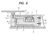
- a mechanism body of the electronic balance including a detecting part has an integral structure in which the hollowed aluminum alloy body and elastic parts are integrally formed into one body. The structure is shown in Figs. 5 and 6.
- a mechanism body 1 is fixed to a base frame 2 by screws 3.
- Sheet-shaped Roberval's parts 4, 5 are respectively formed in an upper and a lower end portion of the mechanism body 1.
- a force coil 7 is fixed to an end portion of the lever 6.
- the other end portion of the lever 6 is connected to a movable part 10 by a connecting part 9.
- the contracted parts are formed at both ends of the connecting part 9.
- a receiving rod 11 is fastened to an upper end portion of the movable part 10.
- a balance pan 12 for measurement is fixed to the receiving rod 11.
- a periphery of the force coil 7 is hollowed out.
- a magnet 8 is fixed to the hollowed portion of the force coil 7.
- a zero position sensor for detecting the displacement using a photo sensor.
- a control circuit is provided except for the aforementioned components. (not shown)
- an object to be measured is put on the balance pan 12.
- the movable part 10 is displaced downward while the balance pan 12 keeping in horizontal position because the upper and the lower face of the movable part 12 are supported by the Roberval's parts 4, 5.
- This downward displacement of the movable part 10 is transmitted to an end portion of the lever 6 by the connecting part 9, and then the end portion of the lever 6 on the force coil 7 side is displaced upward as a fulcrum of the contracted part 6a.
- This displacement of the end portion of the lever 6 is detected by the zero position sensor.
- An electronic current flows in the force coil 7 by the control circuit so that the above displacement can become zero by an attraction force generated by the force coil 7 and the magnet 8. Accordingly, the electronic current proportional to the load of the object put on the balance pan 12, flows in the force coil 7. At this time, an intensity of the electronic current flowing in the force coil 7 is converted into a weight and displayed on a display part, which is not shown in the drawing.
- the electronic balance is composed as described above. Therefore, it is necessary to conduct machining such as screw thread cutting for connecting the base frame 2 to the mechanism body 1. it is also necessary to fasten the receiving rod 11 to the mechanism body 1.
- stress strain parts 3a, 11a are generated in the periphery of a screw thread cutting part 14 of the mechanism body 1. By an influence of this stress strain given to the stress strain parts 3a, 11a, an error is caused when the object to be measured is biased and put on the balance pan 12.
- a distance from the Roberval's parts, 4, 5 to the screw thread cutting part 14 may be sufficiently long so that the measurement cannot be affected by the screw thread cutting part 14.
- the mechanism body 1 is extended in a longitudinal direction.
- the longitudinal direction is defined as a direction from the receiving rod 11 to a joining portion, at which the mechanism body 1 is connected to the base frame 2). Further, it is necessary to optimize a shape of the slit and a position at which the slit is formed. Therefore, it is necessary to apply a complicated technique.
- the mechanism body 1 is extended in the longitudinal direction.
- the balance pan using for measurement is set at the center of the balance. Therefore, when a size only in one direction is extended, it becomes difficult to downsize the electronic balance.
- the present invention has been accomplished in view of the above problems.
- the present invention intends to overcome at least some of the above problems.
- the object is solved by the electronic balance according to independent claim 1. Further advantages, features, aspects and details of the invention are evident from the dependent claims, the description and the accompanying drawings.
- the present invention generally relates to electronic balances.
- an electronic balance for measuring a weight of an article including a Roberval's mechanism for keeping a balance pan in horizontal and a lever mechanism as a lever for transmitting a displacement of a height of a balance pan to a load sensor, which are integrated into one body by hollowing out a base material of the electronic balance.
- the longitudinal direction is defined as a direction from a receiving rod to a joining portion, at which a mechanism body is connected to a base frame.
- an electronic balance comprising:
- a distance from the joining portion to the Roberval's mechanism can be made sufficiently long.
- the electronic balance of the invention has a structure in such a manner that the Roberval's mechanism is not affected by stress strain, which is caused when the screw is fastened, without extending the size of the electronic balance in the longitudinal direction.
- a mechanism body 1 of an electronic balance of the present invention is shown in Figs. 1 and 2.
- protruding portions 1a, 1b which are wide in width, are formed in the mechanism body 1.
- the mechanism body 1 and the base frame 2 are attached to each other.
- a movable part 10 and a receiving rod 11 are also attached to each other via the protruding portions 1a, 1b.
- a screw thread cutting part 14 which is screwed for connecting.
- Fig. 1 is a perspective view showing a state in which the screws are attached.
- the protruding portions 1a, 1b By the protruding portions 1a, 1b, a distance from the screw thread cutting part 14 to the Roberval's parts 4, 5 can be made sufficiently long without extending a size of the electronic balance in a longitudinal direction.
- the longitudinal direction is defined as a direction from the receiving rod 11 to a joining portion, at which the mechanism body 1 is connected to the base frame 2). Therefore, the Roberval's parts 4, 5 are not affected by stress strain generated in a machining portion. Since machining is conducted on the protruding portions 1a, 1b, the size of the electronic balance is transversely increased. However, even if the size in the longitudinal direction is reduced as compared with the conventional structure, the measurement is not affected by the stress strain caused in the screw thread cutting portion 14. Therefore, it becomes possible to put a compact electronic balance of high performance into practical use.
- Fig. 1 is a perspective view showing an appearance of a primary portion of the electronic balance.
- auxiliary connecting metallic fittings 13 are arranged between the movable part 10 and the receiving rod 11. That is, the auxiliary connecting metallic fittings 13 are fixed to the protruding portion 1b by the screws 3.
- the protruding portion 1b is formed so that the width of the side of the movable part 10 is extended transversely.
- the receiving rod 11 is fixed to an upper portion of the auxiliary connecting metallic fittings 13.
- the protruding portion 1a of the mechanism body 1 is fixed to the base frame 2 by the screws 3.
- the electronic balance provided by the present invention is characterized by the shape of the mechanism body 1 as the details are described above.
- the present invention is not limited to the above specific embodiments shown in the drawings. It is possible to adopt a structure in which at least one of the protruding portions 1a, 1b, is arranged.
- the present invention includes various constructions.
- Fig. 3 is a view showing an embodiment of the mechanism body 1 of the present invention.
- the structure of the protruding portion 1a is changed.
- the screw thread cutting portion 14 of the wide width portion 1b relating to the attaching part of the auxiliary connecting metallic fittings 13 can be machined in any direction.
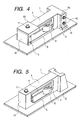
- Fig. 4 is a view showing still another embodiment. In this embodiment, screw thread cutting is not conducted on the protruding portion 1a, but through-holes are formed in the protruding portion 1a, and then the bolts 15 having screws at both end portions are held by the base frame 2 with the nuts 16.
- the connecting method is not limited to joining by screw. It is also possible to join by adhesion or welding.
- the electromagnetic load sensor is used, however, the load sensor is not limited to the electromagnetic type load sensor. It may use various types of load sensors.
- the sensor is arranged inside the integral construction, however, the position at which the sensor is arranged may be an end portion of the integral construction and any other positions.
Landscapes
- Physics & Mathematics (AREA)
- General Physics & Mathematics (AREA)
- Measurement Of Force In General (AREA)
Abstract
Description
Claims (4)
- An electronic balance comprising:wherein at least one of the balance pan and the base frame is connected at the protruding portion.a balance pan for putting an article thereon;a movable part (10) fixed to the balance pan; anda Roberval's mechanism for moving the movable part in parallel in the vertical direction,wherein the movable part, Roberval's mechanism, and each connecting part of the movable part and Roberval's mechanism are formed into an integral construction,a lever mechanism for transmitting a displacement of the movable part to a load sensor;a display device for displaying a weight of the article detected by the load sensor;a base frame for fixing the integral construction; anda protruding portion (1a, 1b) formed at least in a connecting portion where the integral construction is fixed to the base frame (2) and in an attached portion where the balance pan is attached in the integral construction, a width of the protruding portion being larger than that of the Roberval's mechanism,
- The electronic balance according to claim 1, wherein at least one of the balance pan and the base frame is connected at the protruding portion by at least one screw.
- The electronic balance according to claim 1, wherein at least one of the balance pan and the base frame is connected at the protruding portion by adhesion.
- The electronic balance according to claim 1, wherein at least one of the balance pan and the base frame is joined at the protruding portion by welding.
Applications Claiming Priority (2)
| Application Number | Priority Date | Filing Date | Title |
|---|---|---|---|
| JP2001259159 | 2001-08-29 | ||
| JP2001259159A JP2003065834A (en) | 2001-08-29 | 2001-08-29 | Electronic balance |
Publications (3)
| Publication Number | Publication Date |
|---|---|
| EP1288636A2 true EP1288636A2 (en) | 2003-03-05 |
| EP1288636A3 EP1288636A3 (en) | 2003-11-19 |
| EP1288636B1 EP1288636B1 (en) | 2005-09-28 |
Family
ID=19086576
Family Applications (1)
| Application Number | Title | Priority Date | Filing Date |
|---|---|---|---|
| EP02016881A Expired - Lifetime EP1288636B1 (en) | 2001-08-29 | 2002-07-30 | Electronic balance |
Country Status (5)
| Country | Link |
|---|---|
| US (1) | US6787714B2 (en) |
| EP (1) | EP1288636B1 (en) |
| JP (1) | JP2003065834A (en) |
| CN (1) | CN1211646C (en) |
| DE (1) | DE60206339T2 (en) |
Cited By (1)
| Publication number | Priority date | Publication date | Assignee | Title |
|---|---|---|---|---|
| WO2019004898A1 (en) * | 2017-06-27 | 2019-01-03 | Daprox Ab | A weighing device |
Families Citing this family (11)
| Publication number | Priority date | Publication date | Assignee | Title |
|---|---|---|---|---|
| JP4942390B2 (en) | 2006-05-02 | 2012-05-30 | 株式会社エー・アンド・デイ | Electronic balance load measurement mechanism |
| CN101680798B (en) * | 2007-06-01 | 2012-05-09 | 梅特勒-托利多公开股份有限公司 | Adjustable parallel guide especially for a gravimetric measuring instrument |
| EP2175249A1 (en) | 2008-10-13 | 2010-04-14 | Mettler-Toledo AG | Force measuring device |
| WO2010143285A1 (en) * | 2009-06-10 | 2010-12-16 | 日東精工株式会社 | Torque sensor |
| US8770044B2 (en) * | 2009-06-30 | 2014-07-08 | Shinko Denshi Co., Ltd. | Load detection sensor |
| EP2434265B1 (en) * | 2010-09-22 | 2014-03-05 | Wipotec Wiege- und Positioniersysteme GmbH | Weighing device with thermal decoupling |
| CN102809412A (en) * | 2012-08-14 | 2012-12-05 | 昆山大百科实验室设备工程有限公司 | High-performance electromagnetic scale |
| US9400207B2 (en) * | 2013-03-15 | 2016-07-26 | Illinois Tool Works Inc. | Sensor mounting bracket |
| EP3153830B1 (en) * | 2015-10-06 | 2018-06-20 | Mettler-Toledo GmbH | Load receiver with locking means |
| CN105466540A (en) * | 2015-12-13 | 2016-04-06 | 倪德米 | A double-rebound weighing apparatus |
| SE543789C2 (en) * | 2019-09-12 | 2021-07-20 | Daprox Ab | A weighing arrangement configured to be mounted on a lift device |
Family Cites Families (16)
| Publication number | Priority date | Publication date | Assignee | Title |
|---|---|---|---|---|
| US3927560A (en) | 1973-12-20 | 1975-12-23 | Transducers Inc | Moment desensitization of load cells |
| AU515370B2 (en) | 1977-08-01 | 1981-04-02 | Tokyo Electric Co. Ltd. | Integral beam strain gauge weigher |
| US4128001A (en) * | 1977-09-16 | 1978-12-05 | Transducers, Inc. | Parallel beam load cell insensitive to point of application of load |
| US4208905A (en) | 1978-09-22 | 1980-06-24 | Bofors America, Inc. | Miniature load beams |
| US4338825A (en) * | 1980-10-15 | 1982-07-13 | Eaton Corporation | Strain gage load cell |
| DE3568081D1 (en) * | 1985-03-25 | 1989-03-09 | Tron Patent Ag K | Mass-and-force measuring device |
| DE3710997C1 (en) * | 1987-04-01 | 1988-05-26 | Sartorius Gmbh | Upper pan electronic scale with corner load adjustment |
| CN1013709B (en) | 1987-05-09 | 1991-08-28 | 株式会社岛津制作所 | electronic scale |
| DE3802153A1 (en) * | 1988-01-26 | 1989-08-03 | Soehnle Waagen Gmbh & Co | FORCE MEASUREMENT ELEMENT FOR A SCALE |
| SE468023B (en) * | 1991-02-25 | 1992-10-19 | Asea Brown Boveri | LOAD CELL HOUSE WITH BUILT-IN POWER |
| CH682108A5 (en) * | 1991-04-30 | 1993-07-15 | Mettler Toledo Ag | |
| US5220971A (en) * | 1991-09-24 | 1993-06-22 | Sensortronics | Shear beam, single-point load cell |
| US5187448A (en) | 1992-02-03 | 1993-02-16 | Motorola, Inc. | Differential amplifier with common-mode stability enhancement |
| US6472618B1 (en) * | 1999-03-30 | 2002-10-29 | A&D Co., Ltd. | Electronic weighing scale using general purpose block member |
| JP3593954B2 (en) * | 2000-05-31 | 2004-11-24 | 株式会社島津製作所 | Electronic balance |
| US6555767B1 (en) * | 2000-08-22 | 2003-04-29 | Flintec, Inc. | Composite load cell |
-
2001
- 2001-08-29 JP JP2001259159A patent/JP2003065834A/en active Pending
-
2002
- 2002-07-29 US US10/207,724 patent/US6787714B2/en not_active Expired - Fee Related
- 2002-07-30 CN CNB021271968A patent/CN1211646C/en not_active Expired - Fee Related
- 2002-07-30 DE DE60206339T patent/DE60206339T2/en not_active Expired - Lifetime
- 2002-07-30 EP EP02016881A patent/EP1288636B1/en not_active Expired - Lifetime
Cited By (1)
| Publication number | Priority date | Publication date | Assignee | Title |
|---|---|---|---|---|
| WO2019004898A1 (en) * | 2017-06-27 | 2019-01-03 | Daprox Ab | A weighing device |
Also Published As
| Publication number | Publication date |
|---|---|
| EP1288636A3 (en) | 2003-11-19 |
| JP2003065834A (en) | 2003-03-05 |
| CN1401973A (en) | 2003-03-12 |
| US20030042052A1 (en) | 2003-03-06 |
| US6787714B2 (en) | 2004-09-07 |
| EP1288636B1 (en) | 2005-09-28 |
| DE60206339T2 (en) | 2006-07-06 |
| DE60206339D1 (en) | 2005-11-03 |
| CN1211646C (en) | 2005-07-20 |
Similar Documents
| Publication | Publication Date | Title |
|---|---|---|
| US6787714B2 (en) | Electronic balance | |
| JP3234213B2 (en) | Weighing detector | |
| US6693245B2 (en) | Electronic balance which is easily assembled, maintained, downsized and improved with respect to weighing performance, and method for manufacturing the same | |
| US6865961B2 (en) | Force sensor | |
| JP3188784B2 (en) | Load measuring device, especially weigh scale | |
| US20050211003A1 (en) | Foil strain gage | |
| EP0706035B1 (en) | Top pan balance | |
| US7091428B2 (en) | Weighing apparatus with Roberval mechanism | |
| JP3570373B2 (en) | Electronic balance | |
| JPS63277936A (en) | electronic balance | |
| JP6752725B2 (en) | Weighing module with parallel guide mechanism module | |
| JP3117410B2 (en) | Strain body | |
| JP2002296101A (en) | Electronic balance | |
| JP2003247886A (en) | Scale | |
| JP5575129B2 (en) | Load detection sensor | |
| EP1612525B1 (en) | Weighing apparatus with roberval mechanism | |
| JPH07907Y2 (en) | Force detector | |
| JP2002107213A (en) | Electronic force balance | |
| JPWO2000006977A1 (en) | weighing scale | |
| JP3774172B2 (en) | Load cell | |
| EP3645984A1 (en) | A weighing device | |
| JP2002107214A (en) | Electronic force balance | |
| JP5097510B2 (en) | Force measuring mechanism | |
| JP2004239827A (en) | Scale mechanism | |
| JPH0989643A (en) | Balance |
Legal Events
| Date | Code | Title | Description |
|---|---|---|---|
| PUAI | Public reference made under article 153(3) epc to a published international application that has entered the european phase |
Free format text: ORIGINAL CODE: 0009012 |
|
| AK | Designated contracting states |
Kind code of ref document: A2 Designated state(s): AT BE BG CH CY CZ DE DK EE ES FI FR GB GR IE IT LI LU MC NL PT SE SK TR |
|
| AX | Request for extension of the european patent |
Extension state: AL LT LV MK RO SI |
|
| PUAL | Search report despatched |
Free format text: ORIGINAL CODE: 0009013 |
|
| AK | Designated contracting states |
Kind code of ref document: A3 Designated state(s): AT BE BG CH CY CZ DE DK EE ES FI FR GB GR IE IT LI LU MC NL PT SE SK TR |
|
| AX | Request for extension of the european patent |
Extension state: AL LT LV MK RO SI |
|
| 17P | Request for examination filed |
Effective date: 20040120 |
|
| 17Q | First examination report despatched |
Effective date: 20040326 |
|
| AKX | Designation fees paid |
Designated state(s): CH DE LI |
|
| GRAP | Despatch of communication of intention to grant a patent |
Free format text: ORIGINAL CODE: EPIDOSNIGR1 |
|
| GRAS | Grant fee paid |
Free format text: ORIGINAL CODE: EPIDOSNIGR3 |
|
| GRAA | (expected) grant |
Free format text: ORIGINAL CODE: 0009210 |
|
| AK | Designated contracting states |
Kind code of ref document: B1 Designated state(s): CH DE LI |
|
| REG | Reference to a national code |
Ref country code: CH Ref legal event code: EP |
|
| REF | Corresponds to: |
Ref document number: 60206339 Country of ref document: DE Date of ref document: 20051103 Kind code of ref document: P |
|
| REG | Reference to a national code |
Ref country code: CH Ref legal event code: NV Representative=s name: BOVARD AG PATENTANWAELTE |
|
| PLBE | No opposition filed within time limit |
Free format text: ORIGINAL CODE: 0009261 |
|
| STAA | Information on the status of an ep patent application or granted ep patent |
Free format text: STATUS: NO OPPOSITION FILED WITHIN TIME LIMIT |
|
| 26N | No opposition filed |
Effective date: 20060629 |
|
| PGFP | Annual fee paid to national office [announced via postgrant information from national office to epo] |
Ref country code: CH Payment date: 20100714 Year of fee payment: 9 |
|
| REG | Reference to a national code |
Ref country code: CH Ref legal event code: PFA Owner name: SHIMADZU CORPORATION Free format text: SHIMADZU CORPORATION#1, NISHINOKYO-KUWABARACHO, NAKAGYO-KU KYOTO-SHI,#KYOTO 604-8511 (JP) -TRANSFER TO- SHIMADZU CORPORATION#1, NISHINOKYO-KUWABARACHO, NAKAGYO-KU KYOTO-SHI,#KYOTO 604-8511 (JP) |
|
| REG | Reference to a national code |
Ref country code: CH Ref legal event code: PL |
|
| PG25 | Lapsed in a contracting state [announced via postgrant information from national office to epo] |
Ref country code: CH Free format text: LAPSE BECAUSE OF NON-PAYMENT OF DUE FEES Effective date: 20110731 Ref country code: LI Free format text: LAPSE BECAUSE OF NON-PAYMENT OF DUE FEES Effective date: 20110731 |
|
| PGFP | Annual fee paid to national office [announced via postgrant information from national office to epo] |
Ref country code: DE Payment date: 20130724 Year of fee payment: 12 |
|
| REG | Reference to a national code |
Ref country code: DE Ref legal event code: R119 Ref document number: 60206339 Country of ref document: DE |
|
| PG25 | Lapsed in a contracting state [announced via postgrant information from national office to epo] |
Ref country code: DE Free format text: LAPSE BECAUSE OF NON-PAYMENT OF DUE FEES Effective date: 20150203 |
|
| REG | Reference to a national code |
Ref country code: DE Ref legal event code: R119 Ref document number: 60206339 Country of ref document: DE Effective date: 20150203 |