EP1288591A2 - Gas heat pump type air conditioning device, and combustion device for heating exhaust gas - Google Patents
Gas heat pump type air conditioning device, and combustion device for heating exhaust gas Download PDFInfo
- Publication number
- EP1288591A2 EP1288591A2 EP02292142A EP02292142A EP1288591A2 EP 1288591 A2 EP1288591 A2 EP 1288591A2 EP 02292142 A EP02292142 A EP 02292142A EP 02292142 A EP02292142 A EP 02292142A EP 1288591 A2 EP1288591 A2 EP 1288591A2
- Authority
- EP
- European Patent Office
- Prior art keywords
- gas
- exhaust gas
- engine
- heat
- heating
- Prior art date
- Legal status (The legal status is an assumption and is not a legal conclusion. Google has not performed a legal analysis and makes no representation as to the accuracy of the status listed.)
- Withdrawn
Links
Images

Classifications
-
- F—MECHANICAL ENGINEERING; LIGHTING; HEATING; WEAPONS; BLASTING
- F25—REFRIGERATION OR COOLING; COMBINED HEATING AND REFRIGERATION SYSTEMS; HEAT PUMP SYSTEMS; MANUFACTURE OR STORAGE OF ICE; LIQUEFACTION SOLIDIFICATION OF GASES
- F25B—REFRIGERATION MACHINES, PLANTS OR SYSTEMS; COMBINED HEATING AND REFRIGERATION SYSTEMS; HEAT PUMP SYSTEMS
- F25B30/00—Heat pumps
- F25B30/06—Heat pumps characterised by the source of low potential heat
-
- F—MECHANICAL ENGINEERING; LIGHTING; HEATING; WEAPONS; BLASTING
- F25—REFRIGERATION OR COOLING; COMBINED HEATING AND REFRIGERATION SYSTEMS; HEAT PUMP SYSTEMS; MANUFACTURE OR STORAGE OF ICE; LIQUEFACTION SOLIDIFICATION OF GASES
- F25B—REFRIGERATION MACHINES, PLANTS OR SYSTEMS; COMBINED HEATING AND REFRIGERATION SYSTEMS; HEAT PUMP SYSTEMS
- F25B30/00—Heat pumps
-
- F—MECHANICAL ENGINEERING; LIGHTING; HEATING; WEAPONS; BLASTING
- F01—MACHINES OR ENGINES IN GENERAL; ENGINE PLANTS IN GENERAL; STEAM ENGINES
- F01N—GAS-FLOW SILENCERS OR EXHAUST APPARATUS FOR MACHINES OR ENGINES IN GENERAL; GAS-FLOW SILENCERS OR EXHAUST APPARATUS FOR INTERNAL-COMBUSTION ENGINES
- F01N3/00—Exhaust or silencing apparatus having means for purifying, rendering innocuous, or otherwise treating exhaust
- F01N3/08—Exhaust or silencing apparatus having means for purifying, rendering innocuous, or otherwise treating exhaust for rendering innocuous
- F01N3/10—Exhaust or silencing apparatus having means for purifying, rendering innocuous, or otherwise treating exhaust for rendering innocuous by thermal or catalytic conversion of noxious components of exhaust
- F01N3/18—Exhaust or silencing apparatus having means for purifying, rendering innocuous, or otherwise treating exhaust for rendering innocuous by thermal or catalytic conversion of noxious components of exhaust characterised by methods of operation; Control
- F01N3/20—Exhaust or silencing apparatus having means for purifying, rendering innocuous, or otherwise treating exhaust for rendering innocuous by thermal or catalytic conversion of noxious components of exhaust characterised by methods of operation; Control specially adapted for catalytic conversion
- F01N3/2006—Periodically heating or cooling catalytic reactors, e.g. at cold starting or overheating
- F01N3/2033—Periodically heating or cooling catalytic reactors, e.g. at cold starting or overheating using a fuel burner or introducing fuel into exhaust duct
-
- F—MECHANICAL ENGINEERING; LIGHTING; HEATING; WEAPONS; BLASTING
- F01—MACHINES OR ENGINES IN GENERAL; ENGINE PLANTS IN GENERAL; STEAM ENGINES
- F01N—GAS-FLOW SILENCERS OR EXHAUST APPARATUS FOR MACHINES OR ENGINES IN GENERAL; GAS-FLOW SILENCERS OR EXHAUST APPARATUS FOR INTERNAL-COMBUSTION ENGINES
- F01N5/00—Exhaust or silencing apparatus combined or associated with devices profiting by exhaust energy
- F01N5/02—Exhaust or silencing apparatus combined or associated with devices profiting by exhaust energy the devices using heat
-
- F—MECHANICAL ENGINEERING; LIGHTING; HEATING; WEAPONS; BLASTING
- F02—COMBUSTION ENGINES; HOT-GAS OR COMBUSTION-PRODUCT ENGINE PLANTS
- F02G—HOT GAS OR COMBUSTION-PRODUCT POSITIVE-DISPLACEMENT ENGINE PLANTS; USE OF WASTE HEAT OF COMBUSTION ENGINES; NOT OTHERWISE PROVIDED FOR
- F02G5/00—Profiting from waste heat of combustion engines, not otherwise provided for
- F02G5/02—Profiting from waste heat of exhaust gases
- F02G5/04—Profiting from waste heat of exhaust gases in combination with other waste heat from combustion engines
-
- F—MECHANICAL ENGINEERING; LIGHTING; HEATING; WEAPONS; BLASTING
- F25—REFRIGERATION OR COOLING; COMBINED HEATING AND REFRIGERATION SYSTEMS; HEAT PUMP SYSTEMS; MANUFACTURE OR STORAGE OF ICE; LIQUEFACTION SOLIDIFICATION OF GASES
- F25B—REFRIGERATION MACHINES, PLANTS OR SYSTEMS; COMBINED HEATING AND REFRIGERATION SYSTEMS; HEAT PUMP SYSTEMS
- F25B27/00—Machines, plants or systems, using particular sources of energy
-
- F—MECHANICAL ENGINEERING; LIGHTING; HEATING; WEAPONS; BLASTING
- F01—MACHINES OR ENGINES IN GENERAL; ENGINE PLANTS IN GENERAL; STEAM ENGINES
- F01N—GAS-FLOW SILENCERS OR EXHAUST APPARATUS FOR MACHINES OR ENGINES IN GENERAL; GAS-FLOW SILENCERS OR EXHAUST APPARATUS FOR INTERNAL-COMBUSTION ENGINES
- F01N2240/00—Combination or association of two or more different exhaust treating devices, or of at least one such device with an auxiliary device, not covered by indexing codes F01N2230/00 or F01N2250/00, one of the devices being
- F01N2240/02—Combination or association of two or more different exhaust treating devices, or of at least one such device with an auxiliary device, not covered by indexing codes F01N2230/00 or F01N2250/00, one of the devices being a heat exchanger
-
- F—MECHANICAL ENGINEERING; LIGHTING; HEATING; WEAPONS; BLASTING
- F25—REFRIGERATION OR COOLING; COMBINED HEATING AND REFRIGERATION SYSTEMS; HEAT PUMP SYSTEMS; MANUFACTURE OR STORAGE OF ICE; LIQUEFACTION SOLIDIFICATION OF GASES
- F25B—REFRIGERATION MACHINES, PLANTS OR SYSTEMS; COMBINED HEATING AND REFRIGERATION SYSTEMS; HEAT PUMP SYSTEMS
- F25B13/00—Compression machines, plants or systems, with reversible cycle
-
- F—MECHANICAL ENGINEERING; LIGHTING; HEATING; WEAPONS; BLASTING
- F25—REFRIGERATION OR COOLING; COMBINED HEATING AND REFRIGERATION SYSTEMS; HEAT PUMP SYSTEMS; MANUFACTURE OR STORAGE OF ICE; LIQUEFACTION SOLIDIFICATION OF GASES
- F25B—REFRIGERATION MACHINES, PLANTS OR SYSTEMS; COMBINED HEATING AND REFRIGERATION SYSTEMS; HEAT PUMP SYSTEMS
- F25B2313/00—Compression machines, plants or systems with reversible cycle not otherwise provided for
- F25B2313/023—Compression machines, plants or systems with reversible cycle not otherwise provided for using multiple indoor units
-
- F—MECHANICAL ENGINEERING; LIGHTING; HEATING; WEAPONS; BLASTING
- F25—REFRIGERATION OR COOLING; COMBINED HEATING AND REFRIGERATION SYSTEMS; HEAT PUMP SYSTEMS; MANUFACTURE OR STORAGE OF ICE; LIQUEFACTION SOLIDIFICATION OF GASES
- F25B—REFRIGERATION MACHINES, PLANTS OR SYSTEMS; COMBINED HEATING AND REFRIGERATION SYSTEMS; HEAT PUMP SYSTEMS
- F25B2313/00—Compression machines, plants or systems with reversible cycle not otherwise provided for
- F25B2313/025—Compression machines, plants or systems with reversible cycle not otherwise provided for using multiple outdoor units
- F25B2313/0253—Compression machines, plants or systems with reversible cycle not otherwise provided for using multiple outdoor units in parallel arrangements
- F25B2313/02531—Compression machines, plants or systems with reversible cycle not otherwise provided for using multiple outdoor units in parallel arrangements during cooling
-
- F—MECHANICAL ENGINEERING; LIGHTING; HEATING; WEAPONS; BLASTING
- F25—REFRIGERATION OR COOLING; COMBINED HEATING AND REFRIGERATION SYSTEMS; HEAT PUMP SYSTEMS; MANUFACTURE OR STORAGE OF ICE; LIQUEFACTION SOLIDIFICATION OF GASES
- F25B—REFRIGERATION MACHINES, PLANTS OR SYSTEMS; COMBINED HEATING AND REFRIGERATION SYSTEMS; HEAT PUMP SYSTEMS
- F25B2327/00—Compressor driving means
-
- F—MECHANICAL ENGINEERING; LIGHTING; HEATING; WEAPONS; BLASTING
- F25—REFRIGERATION OR COOLING; COMBINED HEATING AND REFRIGERATION SYSTEMS; HEAT PUMP SYSTEMS; MANUFACTURE OR STORAGE OF ICE; LIQUEFACTION SOLIDIFICATION OF GASES
- F25B—REFRIGERATION MACHINES, PLANTS OR SYSTEMS; COMBINED HEATING AND REFRIGERATION SYSTEMS; HEAT PUMP SYSTEMS
- F25B2500/00—Problems to be solved
- F25B2500/02—Increasing the heating capacity of a reversible cycle during cold outdoor conditions
-
- F—MECHANICAL ENGINEERING; LIGHTING; HEATING; WEAPONS; BLASTING
- F25—REFRIGERATION OR COOLING; COMBINED HEATING AND REFRIGERATION SYSTEMS; HEAT PUMP SYSTEMS; MANUFACTURE OR STORAGE OF ICE; LIQUEFACTION SOLIDIFICATION OF GASES
- F25B—REFRIGERATION MACHINES, PLANTS OR SYSTEMS; COMBINED HEATING AND REFRIGERATION SYSTEMS; HEAT PUMP SYSTEMS
- F25B2700/00—Sensing or detecting of parameters; Sensors therefor
- F25B2700/21—Temperatures
- F25B2700/2106—Temperatures of fresh outdoor air
-
- Y—GENERAL TAGGING OF NEW TECHNOLOGICAL DEVELOPMENTS; GENERAL TAGGING OF CROSS-SECTIONAL TECHNOLOGIES SPANNING OVER SEVERAL SECTIONS OF THE IPC; TECHNICAL SUBJECTS COVERED BY FORMER USPC CROSS-REFERENCE ART COLLECTIONS [XRACs] AND DIGESTS
- Y02—TECHNOLOGIES OR APPLICATIONS FOR MITIGATION OR ADAPTATION AGAINST CLIMATE CHANGE
- Y02B—CLIMATE CHANGE MITIGATION TECHNOLOGIES RELATED TO BUILDINGS, e.g. HOUSING, HOUSE APPLIANCES OR RELATED END-USER APPLICATIONS
- Y02B30/00—Energy efficient heating, ventilation or air conditioning [HVAC]
- Y02B30/52—Heat recovery pumps, i.e. heat pump based systems or units able to transfer the thermal energy from one area of the premises or part of the facilities to a different one, improving the overall efficiency
-
- Y—GENERAL TAGGING OF NEW TECHNOLOGICAL DEVELOPMENTS; GENERAL TAGGING OF CROSS-SECTIONAL TECHNOLOGIES SPANNING OVER SEVERAL SECTIONS OF THE IPC; TECHNICAL SUBJECTS COVERED BY FORMER USPC CROSS-REFERENCE ART COLLECTIONS [XRACs] AND DIGESTS
- Y02—TECHNOLOGIES OR APPLICATIONS FOR MITIGATION OR ADAPTATION AGAINST CLIMATE CHANGE
- Y02P—CLIMATE CHANGE MITIGATION TECHNOLOGIES IN THE PRODUCTION OR PROCESSING OF GOODS
- Y02P80/00—Climate change mitigation technologies for sector-wide applications
- Y02P80/10—Efficient use of energy, e.g. using compressed air or pressurized fluid as energy carrier
- Y02P80/15—On-site combined power, heat or cool generation or distribution, e.g. combined heat and power [CHP] supply
-
- Y—GENERAL TAGGING OF NEW TECHNOLOGICAL DEVELOPMENTS; GENERAL TAGGING OF CROSS-SECTIONAL TECHNOLOGIES SPANNING OVER SEVERAL SECTIONS OF THE IPC; TECHNICAL SUBJECTS COVERED BY FORMER USPC CROSS-REFERENCE ART COLLECTIONS [XRACs] AND DIGESTS
- Y02—TECHNOLOGIES OR APPLICATIONS FOR MITIGATION OR ADAPTATION AGAINST CLIMATE CHANGE
- Y02T—CLIMATE CHANGE MITIGATION TECHNOLOGIES RELATED TO TRANSPORTATION
- Y02T10/00—Road transport of goods or passengers
- Y02T10/10—Internal combustion engine [ICE] based vehicles
- Y02T10/12—Improving ICE efficiencies
Definitions
- This invention relates to a gas heat pump type air conditioning device in which a compression device for circulating a refrigerant is driven by a gas engine as a driving source, and the invention particularly relates to a gas heat pump type air conditioning device which can enhance heating capacity when outdoor air temperature is low.
- An air conditioning device which performs air conditioning such as air cooling and air heating by using a heat pump is provided with a refrigerant circuit including components such as an indoor heat exchanger, a compression device, an outdoor heat exchanger, and a throttling structure.
- Air cooling and heating indoors is realized by exchanging heat of indoor air and outdoor air by the indoor heat exchanger and the outdoor heat exchanger during the circulation of a refrigerant.
- the receipt of heat during air heating does not rely on only the outdoor heat exchanger, and a refrigerant heating device may sometimes by provided for directly heating the refrigerant.
- GHP gas heat pump type air conditioning device
- a GHP in a GHP, outstanding air heating effects can be achieved if so-called waste heat such as high temperature exhaust gas exhausted from a gas engine or heat of engine-coolant-water is used as a heat source for the refrigerant during air heating operations, and more efficient use of energy is possible as compared with an EHP (electric heat pump).
- EHP electric heat pump
- the efficiency percentage of energy use of the GHP is 1.2 to 1.5 times higher compared to an EHP.
- apparatuses above, such as a refrigerant heating device need not be installed in the refrigerant circuit if this kind of structure is used.
- defrosting operations necessary for the outdoor heat exchanging device in air heating can be performed by using the exhaust heat of the gas engine.
- the defrosting operation in an EHP is done in such a way that the air heating operation stops and the air cooling operation is temporarily performed to defrost the outdoor heat exchanging device.
- the air heating operation stops and the air cooling operation is temporarily performed to defrost the outdoor heat exchanging device.
- the air heating operation stops and the air cooling operation is temporarily performed to defrost the outdoor heat exchanging device.
- the air heating operation stops and the air cooling operation is temporarily performed to defrost the outdoor heat exchanging device.
- the air heating operation stops and the air cooling operation is temporarily performed to defrost the outdoor heat exchanging device.
- the air heating operation stops and the air cooling operation is temporarily performed to defrost the outdoor heat exchanging device.
- the air cooling operation is temporarily performed to defrost the outdoor heat exchanging device.
- continuous air heating operation is possible because of the above conditions, and problems occuring in the case of an EHP do
- the exhaust heat such as high temperature exhaust gas exhausted from gas engines or waste heat of engine-coolant-water is introduced to a heat exchanging device such as an exhausted gas heat exchanging device or water heat exchanging device during air heating operation; thus, collecting exhaust heat is possible by using such exhaust heat as a heat source for the refrigerant, and outstanding air heating capacity can be obtained differently from EHP.
- engine-coolant-water is heated by exhaust heat during the flowing of exhaust gas exhausted from the gas engine through an exhaust gas heat exchanging device; in addition, the engine-coolant-water absorbs heat while flowing inside a water jacket of the gas engine and cooling the water jacket of the gas engine; thus the temperature of the engine-coolant-water rises.
- the refrigerant can be heated by heat of the engine-coolant-water; thus, the refrigerant can be evaporated sufficiently by cooperation between a water heat exchanging device and an outdoor heat exchanging device, even in an air heating operation when the outdoor air temperature is low.
- an object of this invention is to provide a gas heat pump type air conditioning device in which air heating capacity during low outdoor air temperatures can be improved to be higher. Also, an object of this invention is to provide a gas heat pump type air conditioning device which can exhibit sufficient air heating capacity even when the outdoor air temperature is low.
- the invention has the following construction.
- a refrigerating cycle is formed by circulating the refrigerant by a compression device for which the driving source is a gas engine, waste heat of exhaust gas exhausted from the gas engine is collected to engine coolant water by an exhaust gas heat exchanging device, and the refrigerant is heated by the engine-coolant-water in order to enhance the heating capacity, exhaust gas exhausted from the gas engine is heated, and a heating device which increases the amount of thermal energy collectable in the exhaust gas heat exchanging device.
- the exhaust gas exhausted from the gas engine is heated, and a heating device for increasing the amount of thermal energy which can be collected in the exhaust gas heat exchanging device is provided.
- a heating device for increasing the amount of thermal energy which can be collected in the exhaust gas heat exchanging device is provided.
- the amount of absorbing heat of the engine coolant water in the exhaust gas heat exchanging device increases, and furthermore, the refrigerant is heated by high temperature engine coolant water to expedite the evaporation, and air heating capacity during low outdoor air temperature can be enhanced.
- the heating device should preferably be a combusting device for heating exhaust gas which supplies combustion gas generated by combusting fuel by the combusting device to the exhaust gas; thus, the amount of thermal energy of exhaust gas can be increased easily and reliably.
- the combusting device for heating exhaust gas should preferably be provided in the exhaust gas heat exchanging device, and the amount of absorbed heat of the engine coolant water in the exhaust gas heat exchanging device can be increased efficiently and directly.
- a catalyst container which contains exhaust gas cleaning catalyst be provided in an exhaust system which connects the gas engine and the exhaust gas heat exchanging device, and that the combusting device of the exhaust gas heating device is provided inside the catalyst container.
- the heating device should preferably be operated when a outdoor air temperature detecting device detects a temperature lower than a predetermined value.
- the heating device is operated only under conditions that air heating capacity is insufficient, and total operating efficiency of the device can be enhanced.
- the fuel to be combusted in the combusting device should be the same fuel as for driving the gas engine.
- heating operation with inexpensive gas fuel is possible by using a fuel supply system similar to the gas engine.
- a combusting device for heating exhaust gas is provided in a exhaust gas channel exhausted from a gas engine of a gas heat pump type air conditioning device so as to heat the exhaust gas
- the combusting device for heating exhaust gas is characterized in comprising a hollow combusting device body, a combustion nozzle provided in the combusting device body, a fuel system for supplying fuel and air to the combustion nozzle in a predetermined ratio, a combustion gas supplying channel which supplies combustion gas generated by combusting the fuel with the combustion nozzle, from the combusting device body to exhaust gas exhausted from the gas engine of the gas heat pump type air conditioning device.
- a combusting device for heating exhaust gas is provided in an exhaust gas channel exhausted from a gas engine of a gas heat pump type air conditioning device so as to heat the exhaust gas
- a combusting device for heating exhaust gas comprises a hollow combustion device body the casing of which is compatibly used by an exhaust gas heat exchanging device, a combustion nozzle provided in the combusting device body, a fuel supplying system which supplies fuel and air to the combustion nozzle in a predetermined ratio, the amount of heat of combustion gas generated in the combusting device body by combusting the fuel with the combustion nozzle being added to the amount of heat of exhaust gas which is exhausted from the gas engine of the gas heat pump type air conditioning device and passes through the combustion device body.
- the amount of heat of the combustion gas generated in the exhaust gas heat exchanging device is equal to the amount of heat of exhaust gas directly, and it is possible to heat engine coolant water in the exhaust gas heat exchanging device efficiently.
- a combustion device for heating exhaust gas according to the seventh aspect of the present invention is provided in an exhaust gas channel exhausted from a gas engine of a gas heat pump type air conditioning device so as to heat the exhaust gas
- this combustion device for heating exhaust gas comprises a hollow combustion device body a casing of which is compatibly used by a catalyst container which contains exhaust gas cleaning catalyst, a combustion nozzle provided in the combustion device body, a fuel supplying system which supplies fuel and air to the combustion nozzle in a predetermined ratio, the amount of heat of combustion gas generated by combusting the fuel with the combustion nozzle being added to the amount of heat of exhaust gas which is exhausted from the gas engine of the gas heat pump type air conditioning device and passes through the combustion device body.
- combustion device for heating exhaust gas it is possible to clean the exhaust gas of a gas engine and the fuel gas by the exhaust gas cleaning catalyst, and it is also possible for the amount of heat in combustion gas to be equal to an amount of heat of exhaust gas so as to raise the temperature of the exhaust gas.
- An additional advantage of raising the temperature of the exhaust gas is that the cleaning operation of the exhaust gas by the catalyst is expedited.
- GHP gas heat pump type air conditioning device
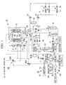
- FIG. 1 is a system diagram showing an overall construction of an air heating system of a GHP as a first embodiment of the present invention.
- This drawing generally shows an indoor unit 1 and an outdoor unit 10 provided with device such as a compression device for driving the gas engine.
- device such as a compression device for driving the gas engine.
- one or a plurality of indoor unit 1 and outdoor unit 10 are connected by refrigerant pipe 2 in such a way that the refrigerant can circulate.
- the indoor unit 1 is provided with an indoor heat exchanging device 1a which functions as an evaporator which evaporates the low temperature low pressure liquid refrigerant so as to remove heat from indoor air (indoor atmosphere) during air cooling operation and functions as a condenser which liquefies the high temperature high pressure gas refrigerant so as to heat the indoor air during air heating operation.
- an indoor heat exchanging device 1a which functions as an evaporator which evaporates the low temperature low pressure liquid refrigerant so as to remove heat from indoor air (indoor atmosphere) during air cooling operation and functions as a condenser which liquefies the high temperature high pressure gas refrigerant so as to heat the indoor air during air heating operation.
- a throttle structure 1b is provided for each indoor heat exchanging device 1a.
- the outdoor unit 10 is internally divided into two major sections.
- the first major section is a section forming a refrigerant circuit primarily by equipment such as a compression device and outdoor heat exchanging device together with the indoor unit 1, and the first major constructing section is called hereinafter the "refrigerant circuit section".
- the second major section is a section provided with equipment such as a gas engine for driving the compression device together with auxiliary equipment, and the second major section is called hereinafter the "gas engine section".
- equipment such as compression device 11, outdoor heat exchanging device 12, water heat exchanging device 13, accumulator 14, receiver 15, oil separator 16, throttling construction 17, 4-way valve 18, solenoid valve 19, check valve 20, and control valve 21 are provided.
- a compression device 11 is operated by a gas engine GE as a driving source (which is to be described later), and the compression device 11 compresses the low temperature low pressure gas refrigerant taken from any one of indoor heat exchanging device 1a or outdoor heat exchanging device 12 and discharges it as high temperature high pressure gas refrigerant.
- the refrigerant can radiate the heat to the outdoor air through the outdoor heat exchanging device 12 during air cooling operation, even if the outdoor air temperature is high. Also, the refrigerant can give heat to indoor air through the indoor heat exchanging device 12 during air heating operation.
- the outdoor heat exchanging device 12 functions as a condenser which liquefies the high temperature high pressure gas refrigerant and radiates it to the outdoor air during the air cooling operation, and in contrast, the outdoor heat exchanging device 12 functions as an evaporator which evaporates the low temperature low pressure liquid refrigerant and removes heat from outdoor air during the air heating operation. That is, the outdoor heat exchanging device 12 performs a reverse operation to the above indoor heat exchanging device 1a during air cooling operation and air heating operation.
- the outdoor heat exchanging device 12 is provided in neighboring radiator 33 of the gas engine GE which is to be described later.
- the radiator 33 is a heat exchanging device which refrigerates the engine-coolant-water of the gas engine GE-by exchanging heat with the outdoor air.
- the water heat exchanging device 13 provided in order that the refrigerant collect heat from the engine-coolant-water of the gas engine GE (which is to be mentioned later). That is, in the air heating operation, the refrigerant does not rely only on the exchange of heat in the indoor heat exchanging device 12, and it becomes possible to collect waste heat from the engine-coolant-water of the gas engine GE; thus, the effect of air heating operation can be enhanced.
- Accumulator 14 is provided in order to store the liquid contained in the gas refrigerant flowing into the compression device 11.
- Receiver 15 is provided in order to separate the refrigerant liquefied by the heat exchanging device which functions as a condenser into gas and liquid, and to store the surplus refrigerant as liquid in the refrigerating cycle.
- Oil separator 16 is provided in order to separate oil contained in the refrigerant and to return the refrigerant back to the compression device 11.
- Throttling construction 17 is provided in order to reduce the pressure of condensed high temperature high pressure liquid refrigerant and to expand the liquid refrigerant so as to produce low temperature low pressure liquid refrigerant.
- a constant pressure expansion valve, thermostatic expansion valve, and capillary tube are selectively used as a throttling construction 17 according to the purpose.
- 4-way valve 18 is provided on the refrigerant pipe 2 in order to selectively change the channel of refrigerant and the direction of flow.
- four ports such as D, C, S, and E are provided.
- Port D is connected to the discharging side of the compression device 11 by the refrigerant pipe 2.
- Port C is connected to the outdoor heat exchanging device 12 by the refrigerant pipe 2.
- Port S is connected to the absorbing side of the compression device 11 by the refrigerant pipe 2.
- Port E is connected to the indoor heat exchanging device 1a by the refrigerant pipe 2.
- the gas engine GE is connected to a compression device 11 which is provided in the refrigerant circuit by a shaft, a belt and the like; thus, the driving force is conducted from the gas engine GE to the compression device 11.
- the coolant water system 30 is provided with a water pump 31, reservoir tank 32, a radiator 33 and the like.
- This coolant water system 30 chills the gas engine GE by the engine-coolant-water which circulates in the circuit shown by a dashed line organized by connecting these elements by pipes.
- a water pump 31 is provided for circulating the coolant water of the gas engine GE in the circuit.
- a reservoir tank 32 is provided for storing the surplus of the coolant water flowing in this circuit temporarily, and for supplying the surplus to the circuit in case the coolant water is in short supply.
- a radiator 33 is constructed integrally with an outdoor heat exchanging device 12.
- a radiator 33 is provided for radiating the heat which the engine-coolant-water removes from the gas engine GE to the outdoor air.
- an exhaust gas heat exchanging device 34 is provided in the coolant water system 30, in addition to the above elements.
- This exhaust gas heat exchanging device 34 is provided for collecting the heat of exhaust gas exhausted from the gas engine GE to the engine-coolant-water.
- a water heat exchanging device 13 (which was mentioned hereinbefore) is disposed in such a way that the coolant water system 30 spans two systems such as the refrigerant circuit section and the coolant water system 30.
- the total construction of the coolant water system 30 is such that the engine-coolant-water not only removes heat from the gas engine GE but also collects heat from exhaust gas during air heating operation; thus, the collected heat is given to the refrigerant from the engine-coolant-water through the water heat exchanging device 13.
- flow control of engine-coolant-water in the coolant water system 30 is performed by flow control valves 35A and 35B provided in two places.
- An exhaust gas system 50 is a system for releasing the exhaust gas of the gas engine GE to the atmosphere, and an exhaust gas system 50 is provided with a muffler 51 and a top of exhaust flue 52.
- exhaust gas exhausted from the gas engine GE passes through above exhaust gas heat exchanging device 34 and heats the engine coolant water; it is then released to the atmosphere from the top of exhaust flue 52.
- a fuel absorbing system 60 is provided with a gas regulator 61, a gas solenoid valve 62, a gas connection port 63 and the like.
- This fuel absorbing system 60 is a system for supplying municipal gas such as liquefied natural gas (LNG) as gas fuel to the gas engine GE.
- a gas regulator 61 is provided for adjusting the delivery pressure of gas fuel which is supplied externally via a gas solenoid valve 62 and a gas connection port 63. The gas fuel for which the pressure is adjusted by this gas regulator 61 is supplied to a combustion chamber of the gas engine GE after being mixed with the air absorbed from the absorbing port (not shown in the drawing).
- an exhaust gas heating device 55 for heating exhaust gas exhausted from the gas engine and for increasing the quantity of thermal energy collectable in the exhaust gas heat exchanging device 34 is provided in exhaust gas system 50 which connects the gas engine GE and the exhaust gas heat exchanging device 34.
- This exhaust gas heating device 55 increases the quantity of thermal energy which is retained by further heating high temperature exhaust gas exhausted from the gas engine GE with another heating source, or by adding (mixing) high temperature combustion gas retaining large quantity of thermal energy.
- valves if a valve in the drawing is filled in black, the valve is open.
- the direction of the flow of the refrigerant and the engine-coolant-water are shown by arrows.
- High temperature high pressure gas refrigerant exchanges heat with the indoor air in the indoor heat exchanging device 1a to be liquefied.
- the gas refrigerant radiates heat to heat the indoor air, and after that, the gas refrigerant becomes high temperature high pressure liquid refrigerant.
- This liquid refrigerant flows passing a throttling construction 1b, an operating valve 21 and a receiver 15, consequently this liquid refrigerant is separated into gas and liquid content.
- the liquid refrigerant discharged from the receiver 15 is introduced to the refrigerant pipe 2 to be divided, either portion of which is sent to the water heat exchanging device 13 via the throttling construction 17a of the constant pressure expansion valve.
- the other liquid refrigerant is sent to the outdoor heat exchanging device 12 through the solenoid valve 18 which is made to open and the throttling construction 17b of the thermal expansion valve.
- the pressure of liquid refrigerant sent to the water heat exchanging device 13 is reduced by passing through the throttling construction 17a; thus, the liquid refrigerant becomes low temperature low pressure refrigerant.
- low temperature low pressure liquid refrigerant is evaporated by absorbing heat from the engine-coolant-water, thus becoming low temperature low pressure gas refrigerant.
- water heat exchanging device 13 and the outdoor heat exchanging device 12 for evaporating the liquid refrigerant either one can be chosen favorably according to the operating conditions such as outdoor air temperature. Also combined use is possible according to the construction of the device.
- Such a refrigerant which becomes low temperature low pressure gas is introduced to the accumulator 14 from the port C of 4-way valve 18 via the port S, the gas and liquid content of the refrigerant is separated and are then taken into the compression device 11.
- the gas refrigerant taken into the compression device 11 is compressed by the operation of the compression device 11 to become high temperature high pressure gas refrigerant, and is sent to the indoor heat exchanging device 1a again; thus, the refrigerating cycle in which the refrigerant repeatedly changes state can be formed.
- the exhaust gas heating device 55 is operated to increase the quantity of thermal energy of exhaust gas exhausted from the gas engine GE.
- the quantity of thermal energy for heating the engine coolant water in the exhaust gas heat exchanging device 34 increases; thus, the temperature of the engine coolant water can be higher; in other words, the engine coolant water retaining a larger quantity of thermal energy can be supplied to the water heat exchanging device 13.
- low temperature low pressure liquid refrigerant can be evaporated by receiving more thermal energy from the engine-coolant-water in the water heat exchanging device 13. Therefore, for example, even in cold areas where the outdoor air temperature may be below -15°C, a sufficient amount of heat can be obtained without relying on the heat to be absorbed from the outdoor air. That is, even if it is impossible to absorb heat from outdoor air, it is possible to obtain a sufficient amount of heat for the heating operation to enable the refrigerating cycle to properly function and to demonstrate the heating capacity satisfactorily.
- the high temperature high pressure gas refrigerant is evaporated in the outdoor heat exchanging device 12 to discharge heat to outdoor air; thus, the refrigerant becomes high temperature high pressure liquid refrigerant.
- This liquid refrigerant is introduced to the receiver 15 through the check valve 20.
- the liquid refrigerant separated into gas and liquid components in the receiver 15 is introduced to the throttling construction 1b through the operating valve 21; then the pressure is reduced in the process of passing through the throttling construction 1b resulting in low temperature low pressure liquid refrigerant, then the liquid refrigerant is sent to the indoor heat exchanging device 1a which functions as an evaporator.
- the low temperature low pressure liquid refrigerant sent to the indoor heat exchanging device 1 a removes heat from the indoor air and is evaporated. In this process, this refrigerant chills the indoor air and becomes low temperature low pressure gas refrigerant, and is introduced to the 4-way valve 18 through the operating valve 21 and the refrigerant pipe 2.
- the low temperature low pressure gas refrigerant introduced to the 4-way valve 18 flows into the accumulator 14 from the port E via the port S. After the liquid content is separated here, the gas refrigerant is absorbed in the compression device 11. The gas refrigerant absorbed by the compression device 11 is compressed by the operation of the compression device and becomes high temperature high pressure gas refrigerant to be sent to the outdoor heat exchanging device 12; thus, the refrigerating cycle where the refrigerant repeatedly changes state can be formed.
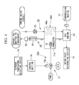
- a combustion device for heating exhaust gas 70 is provided as a exhaust gas heating device exhausted from the gas engine GE and for increasing quantity of thermal energy collectable in the exhaust gas heat exchanging device 34.
- This combustion device for heating exhaust gas 70 comprises a hollow combusting device body 71, a combustion nozzle 72 provided in the combusting device body 71, a fuel supplying system 73 which supplies fuel and air to the combustion nozzle in a predetermined mixture ratio, a combustion gas supplying channel 94 which supplies combustion gas generated by combusting the fuel with the combustion nozzle 72, from the combustor 71 to exhaust gas exhausted from the gas engine GE.
- combustion gas generated by combusting fuel in the combustor 71 is mixed with the exhaust gas exhausted from the gas engine GE of the gas heat pump type air conditioning device via combustion gas supplying channel 94 so as to be supplied to the exhaust gas system 50.
- combustion gas supplying channel 94 joins to a piping of the exhaust system 50 between the gas engine GE and the exhaust gas heat exchanging device 34
- combustion gas may be supplied directly inside the exhaust gas heat exchanging device 34.
- a control valve 73a is provided, air-fuel mixture in which fuel and air are mixed in appropriate ratio is supplied to the combustion nozzle 72 via this control valve 73a.
- the control valve 73a opens when a combustion device for heating exhaust gas 70 operates, in other words, when an outdoor air temperature detecting device 74 detects a temperature lower than a predetermined value during air heating operation and a control signal output from the control section 75 is received.
- a temperature sensor which can be provided in an appropriate place near the outdoor unit.
- the condition of outdoor air can be determined depending on the condition of the refrigerant such as temperature and pressure detected by various sensors which are provided in the channel for circulating the refrigerant.
- control section 75 When a detecting signal indicating a low outdoor temperature is input to the control section 75, the control section 75 opens the control valve 73a to supply fuel and air to the combustion nozzle 72, and the air-fuel mixture is ignited in the combustion nozzle 72.
- the fuel to be used in above combusting device for heating exhaust gas 70 should preferably be the gas fuel such as municipal gas which is used similarly as gas engine GE. This is because the gas engine GE and the fuel system can used compatibly, and additionally the cost of the fuel is low.
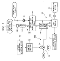
- the combustion nozzle 72 of the combusting device for heating exhaust gas 70A is provided inside the hollow combustion device body 71A which can be compatible with the exhaust gas heat exchanging device 34A and the casing.
- Other factors are similar to the second embodiment as shown in FIG. 3, and the same reference numerals are used and detailed explanation is omitted.
- this combustion device for heating exhaust gas 70A which is constructed in such a way, the amount of heat of the combustion gas generated inside the combustion device body 71A is directly added to the exhaust gas passing through the exhaust gas heat exchanging device 34A by combusting the air-fuel mixture in the combustion nozzle 72.
- the engine coolant water flowing through the group of pipes 34a can be heated highly efficiently with no thermal loss, and also, it can be expected that exhaust gas and engine coolant water are heated by radiated heat from the flame.
- the combustion nozzle 72 of the combustion device for heating exhaust gas 70B is provided in hollow combusting device body 71B which is compatible with the catalyst container which contains the exhaust gas cleaning catalyst 80.
- Other factors are similar to the third embodiment as shown in FIG. 3, and the same reference numerals are used and detailed explanation is omitted.
- the combusting device for heating exhaust gas 70B containing the exhaust gas cleaning catalyst 80 is provided in the exhaust system 50 to be located between the gas engine and the exhaust gas heat exchanging device 34.
- an exhaust gas cleaning catalyst 80 for example, a rhodium catalytic converter is preferably used. By constructing it in this way, it is possible to increase the heat for heating the engine coolant water at the same time as cleaning the exhaust gas of gas engine GE and the exhaust gas.
- the cleaning of exhaust gas by the exhaust gas cleaning catalyst 80 can be done more efficiently under conditions in which the exhaust gas is at a high temperature; therefore, raising the temperature of the exhaust gas by adding combustion gas can also lead to the promotion of clearing the combustion gas by the catalyst.
- the exhaust gas heating device 55 which can heat the exhaust gas according to necessity during air heating operation is provided; thus, more heat is added to the waste heat of the engine, and therefore it is possible to supply more thermal energy to exhaust gas heat exchanging device 34 and the engine coolant water can be heated to higher temperatures than conventionally.
- the refrigerant can be evaporated in the water heat exchanging device 13 by exchanging heat with high temperature engine coolant water retaining large amounts of thermal energy. Accordingly, the refrigerating cycle can be maintained by using heat supplied from the waste heat of the engine and the exhaust gas heating device 55 even during periods of low outdoor air temperature in which sufficient amounts of heat necessary to evaporate the refrigerant in outdoor heat exchanging device 12 cannot be obtained from outdoor air; thus, sufficient air heating operating capacity is obtained, and air heating capacity can be enhanced even during periods of low outdoor air temperature.
- present invention is not limited to above embodiment, and for example, factors such as the number or variations of devices relating to the refrigerating cycle can be preferably changed within the scope of the features of present invention.
Landscapes
- Engineering & Computer Science (AREA)
- Mechanical Engineering (AREA)
- General Engineering & Computer Science (AREA)
- Chemical & Material Sciences (AREA)
- Combustion & Propulsion (AREA)
- Thermal Sciences (AREA)
- Physics & Mathematics (AREA)
- Chemical Kinetics & Catalysis (AREA)
- Health & Medical Sciences (AREA)
- Toxicology (AREA)
- Compression-Type Refrigeration Machines With Reversible Cycles (AREA)
- Exhaust Gas After Treatment (AREA)
- Air Conditioning Control Device (AREA)
Abstract
In order to obtain more enhanced air heating capacity during low outdoor air
temperature, a gas heat pump type air conditioning device which
circulates refrigerant by a compressing device (11) of which driving source is a gas engine, forms a refrigerating cycle, collects waste heat of exhaust gas exhausted from the gas engine to engine coolant water by an exhaust gas heat exchanging device (34), and heats the refrigerant by the engine coolant water to enhance the heating capacity, the exhaust gas exhausted from the gas engine is heated, and a heating device for increasing amount of thermal energy which can be collected in the exhaust gas heat exchanging device (34) is provided.
circulates refrigerant by a compressing device (11) of which driving source is a gas engine, forms a refrigerating cycle, collects waste heat of exhaust gas exhausted from the gas engine to engine coolant water by an exhaust gas heat exchanging device (34), and heats the refrigerant by the engine coolant water to enhance the heating capacity, the exhaust gas exhausted from the gas engine is heated, and a heating device for increasing amount of thermal energy which can be collected in the exhaust gas heat exchanging device (34) is provided.
Description
This invention relates to a gas heat pump type air conditioning device in which a
compression device for circulating a refrigerant is driven by a gas engine as a driving
source, and the invention particularly relates to a gas heat pump type air conditioning
device which can enhance heating capacity when outdoor air temperature is low.
An air conditioning device which performs air conditioning such as air cooling
and air heating by using a heat pump is provided with a refrigerant circuit including
components such as an indoor heat exchanger, a compression device, an outdoor heat
exchanger, and a throttling structure. Air cooling and heating indoors is realized by
exchanging heat of indoor air and outdoor air by the indoor heat exchanger and the
outdoor heat exchanger during the circulation of a refrigerant. Also, in this refrigerant
circuit, the receipt of heat during air heating does not rely on only the outdoor heat
exchanger, and a refrigerant heating device may sometimes by provided for directly
heating the refrigerant.
Recently, regarding a driving source for the compression device which is
provided in the above refrigerant circuit, a driving source employing a gas engine has been
developed to replace electric motors which are commonly used. This air conditioning
device employing a gas engine is generally called a gas heat pump type air conditioning
device (hereinafter called a GHP). By this GHP, because municipal gas or the like,
which are relatively inexpensive, can be used as fuel, the running cost is not increased
because it is different from an electric heat pump provided with a compression device
using electric motors (hereinafter called EHP), therefore cost can be reduced for
consumers.
Also, in a GHP, outstanding air heating effects can be achieved if so-called waste
heat such as high temperature exhaust gas exhausted from a gas engine or heat of
engine-coolant-water is used as a heat source for the refrigerant during air heating
operations, and more efficient use of energy is possible as compared with an EHP (electric
heat pump). In addition, in this case, the efficiency percentage of energy use of the GHP
is 1.2 to 1.5 times higher compared to an EHP. Also, apparatuses above, such as a
refrigerant heating device, need not be installed in the refrigerant circuit if this kind of
structure is used.
Additionally, in a GHP, defrosting operations necessary for the outdoor heat
exchanging device in air heating can be performed by using the exhaust heat of the gas
engine. Generally, the defrosting operation in an EHP is done in such a way that the air
heating operation stops and the air cooling operation is temporarily performed to defrost
the outdoor heat exchanging device. In this case, because cold air flows into the room,
comfortableness inside the room is deteriorated. In contrast, in a GHP, continuous air
heating operation is possible because of the above conditions, and problems occuring in
the case of an EHP do not arise.
As mentioned above, in a GHP, the exhaust heat such as high temperature exhaust
gas exhausted from gas engines or waste heat of engine-coolant-water is introduced to a
heat exchanging device such as an exhausted gas heat exchanging device or water heat
exchanging device during air heating operation; thus, collecting exhaust heat is possible
by using such exhaust heat as a heat source for the refrigerant, and outstanding air heating
capacity can be obtained differently from EHP.
In conventional GHPs, engine-coolant-water is heated by exhaust heat during the
flowing of exhaust gas exhausted from the gas engine through an exhaust gas heat
exchanging device; in addition, the engine-coolant-water absorbs heat while flowing
inside a water jacket of the gas engine and cooling the water jacket of the gas engine; thus
the temperature of the engine-coolant-water rises.
If such high temperature engine-coolant-water, which collected the exhaust heat
from the gas engine, is sent to a water heat exchanging device, the refrigerant can be
heated by heat of the engine-coolant-water; thus, the refrigerant can be evaporated
sufficiently by cooperation between a water heat exchanging device and an outdoor heat
exchanging device, even in an air heating operation when the outdoor air temperature is
low.
However, there is a limit to the above improvement of the heating capacity
achieved by collecting exhaust heat; thus, in other words, there is a limit to the amount of
exhaust heat which is collectable; therefore, there has been a limit on the improvement of
air heating capacity when the outdoor air temperature is low. In particular, in a case such
as that above when a GHP is used in cold areas where the outdoor air temperatures are
very low, the amount of heat absorbed from outdoor air in the outdoor heat exchanging
device decreases extremely; thus, it is difficult to obtain necessary amounts of heat to
sufficiently evaporate the refrigerant.
Accordingly, in order to enable a gas heat pump type air conditioning device to
demonstrate sufficient air heating capacity even in an air heating operation in cold areas
where outdoor air temperature may be below -15°C so as to provide a comfortable indoor
environment, it is necessary to obtain sufficient amounts of heat to evaporate the
refrigerant when the outdoor air temperature is low, and to improve the air heating
capacity to be higher.
This invention was made in consideration of above conditions. Thus an object of
this invention is to provide a gas heat pump type air conditioning device in which air
heating capacity during low outdoor air temperatures can be improved to be higher. Also,
an object of this invention is to provide a gas heat pump type air conditioning device
which can exhibit sufficient air heating capacity even when the outdoor air temperature is
low.
In order to solve the above problems, the invention has the following
construction.
In a gas heat pump type air conditioning device according to the first aspect of
this invention, a refrigerating cycle is formed by circulating the refrigerant by a
compression device for which the driving source is a gas engine, waste heat of exhaust gas
exhausted from the gas engine is collected to engine coolant water by an exhaust gas heat
exchanging device, and the refrigerant is heated by the engine-coolant-water in order to
enhance the heating capacity, exhaust gas exhausted from the gas engine is heated, and a
heating device which increases the amount of thermal energy collectable in the exhaust
gas heat exchanging device.
According to such gas heat pump type air conditioning device, the exhaust gas
exhausted from the gas engine is heated, and a heating device for increasing the amount of
thermal energy which can be collected in the exhaust gas heat exchanging device is
provided. Thus, the amount of absorbing heat of the engine coolant water in the exhaust
gas heat exchanging device increases, and furthermore, the refrigerant is heated by high
temperature engine coolant water to expedite the evaporation, and air heating capacity
during low outdoor air temperature can be enhanced.
In the gas heat pump type air conditioning device according to the first aspect of
the present invention, the heating device should preferably be a combusting device for
heating exhaust gas which supplies combustion gas generated by combusting fuel by the
combusting device to the exhaust gas; thus, the amount of thermal energy of exhaust gas
can be increased easily and reliably.
In the gas heat pump type air conditioning device according to the second aspect
of the present invention, the combusting device for heating exhaust gas should preferably
be provided in the exhaust gas heat exchanging device, and the amount of absorbed heat
of the engine coolant water in the exhaust gas heat exchanging device can be increased
efficiently and directly.
In the gas heat pump type air conditioning device according to the second aspect
of the present invention, it is preferable that a catalyst container which contains exhaust
gas cleaning catalyst be provided in an exhaust system which connects the gas engine and
the exhaust gas heat exchanging device, and that the combusting device of the exhaust gas
heating device is provided inside the catalyst container. Thus, exhaust gas can be
cleaned, and the amount of thermal energy of exhaust gas can be increased.
In the gas heat pump type air conditioning device according to the third aspect of
the present invention, the heating device should preferably be operated when a outdoor air
temperature detecting device detects a temperature lower than a predetermined value.
The heating device is operated only under conditions that air heating capacity is
insufficient, and total operating efficiency of the device can be enhanced.
In the gas heat pump type air conditioning device according to the fourth aspect
of the present invention, the fuel to be combusted in the combusting device should be the
same fuel as for driving the gas engine. Thus heating operation with inexpensive gas
fuel is possible by using a fuel supply system similar to the gas engine.
In the combusting device for heating exhaust gas according to the fifth aspect of
the present invention, a combusting device for heating exhaust gas is provided in a exhaust
gas channel exhausted from a gas engine of a gas heat pump type air conditioning device
so as to heat the exhaust gas, and the combusting device for heating exhaust gas is
characterized in comprising a hollow combusting device body, a combustion nozzle provided in the combusting device body, a fuel system for supplying fuel and air to the combustion nozzle in a predetermined ratio, a combustion gas supplying channel which supplies combustion gas generated by combusting the fuel with the combustion nozzle, from the combusting device body to exhaust gas exhausted from the gas engine of the gas heat pump type air conditioning device.
characterized in comprising a hollow combusting device body, a combustion nozzle provided in the combusting device body, a fuel system for supplying fuel and air to the combustion nozzle in a predetermined ratio, a combustion gas supplying channel which supplies combustion gas generated by combusting the fuel with the combustion nozzle, from the combusting device body to exhaust gas exhausted from the gas engine of the gas heat pump type air conditioning device.
According to such a combusting device for heating exhaust gas, it is possible to
generate high temperature combustion gas easily to supply such combustion gas to
exhaust gas, and it is also possible to raise the temperature of the exhaust gas.
A combusting device for heating exhaust gas according to the sixth aspect of the
present invention is provided in an exhaust gas channel exhausted from a gas engine of a
gas heat pump type air conditioning device so as to heat the exhaust gas, and a combusting
device for heating exhaust gas comprises a hollow combustion device body the casing of
which is compatibly used by an exhaust gas heat exchanging device, a combustion nozzle
provided in the combusting device body, a fuel supplying system which supplies fuel and
air to the combustion nozzle in a predetermined ratio, the amount of heat of combustion
gas generated in the combusting device body by combusting the fuel with the combustion
nozzle being added to the amount of heat of exhaust gas which is exhausted from the gas
engine of the gas heat pump type air conditioning device and passes through the
combustion device body.
According to such a combustion device for heating exhaust gas, the amount of
heat of the combustion gas generated in the exhaust gas heat exchanging device is equal to
the amount of heat of exhaust gas directly, and it is possible to heat engine coolant water
in the exhaust gas heat exchanging device efficiently.
A combustion device for heating exhaust gas according to the seventh aspect of
the present invention is provided in an exhaust gas channel exhausted from a gas engine of
a gas heat pump type air conditioning device so as to heat the exhaust gas, and this
combustion device for heating exhaust gas comprises a hollow combustion device body a
casing of which is compatibly used by a catalyst container which contains exhaust gas
cleaning catalyst, a combustion nozzle provided in the combustion device body, a fuel
supplying system which supplies fuel and air to the combustion nozzle in a predetermined
ratio, the amount of heat of combustion gas generated by combusting the fuel with the
combustion nozzle being added to the amount of heat of exhaust gas which is exhausted
from the gas engine of the gas heat pump type air conditioning device and passes through
the combustion device body.
According to such a combustion device for heating exhaust gas, it is possible to
clean the exhaust gas of a gas engine and the fuel gas by the exhaust gas cleaning catalyst,
and it is also possible for the amount of heat in combustion gas to be equal to an amount
of heat of exhaust gas so as to raise the temperature of the exhaust gas. An additional
advantage of raising the temperature of the exhaust gas is that the cleaning operation of
the exhaust gas by the catalyst is expedited.
An embodiment of a gas heat pump type air conditioning device (hereinafter
called a GHP) according to the present invention is explained with reference to drawings
as follows.
FIG. 1 is a system diagram showing an overall construction of an air heating
system of a GHP as a first embodiment of the present invention. This drawing generally
shows an indoor unit 1 and an outdoor unit 10 provided with device such as a compression
device for driving the gas engine. In addition, one or a plurality of indoor unit 1 and
outdoor unit 10 are connected by refrigerant pipe 2 in such a way that the refrigerant can
circulate.
The indoor unit 1 is provided with an indoor heat exchanging device 1a which
functions as an evaporator which evaporates the low temperature low pressure liquid
refrigerant so as to remove heat from indoor air (indoor atmosphere) during air cooling
operation and functions as a condenser which liquefies the high temperature high pressure
gas refrigerant so as to heat the indoor air during air heating operation. In addition, a
throttle structure 1b is provided for each indoor heat exchanging device 1a.
The outdoor unit 10 is internally divided into two major sections.
The first major section is a section forming a refrigerant circuit primarily by
equipment such as a compression device and outdoor heat exchanging device together
with the indoor unit 1, and the first major constructing section is called hereinafter the
"refrigerant circuit section".
The second major section is a section provided with equipment such as a gas
engine for driving the compression device together with auxiliary equipment, and the
second major section is called hereinafter the "gas engine section".
In the refrigerant circuit section, equipment such as compression device 11,
outdoor heat exchanging device 12, water heat exchanging device 13, accumulator 14,
receiver 15, oil separator 16, throttling construction 17, 4-way valve 18, solenoid valve 19,
check valve 20, and control valve 21 are provided.
A compression device 11 is operated by a gas engine GE as a driving source
(which is to be described later), and the compression device 11 compresses the low
temperature low pressure gas refrigerant taken from any one of indoor heat exchanging
device 1a or outdoor heat exchanging device 12 and discharges it as high temperature high
pressure gas refrigerant. By this construction, the refrigerant can radiate the heat to the
outdoor air through the outdoor heat exchanging device 12 during air cooling operation,
even if the outdoor air temperature is high. Also, the refrigerant can give heat to indoor
air through the indoor heat exchanging device 12 during air heating operation.
The outdoor heat exchanging device 12 functions as a condenser which liquefies
the high temperature high pressure gas refrigerant and radiates it to the outdoor air during
the air cooling operation, and in contrast, the outdoor heat exchanging device 12 functions
as an evaporator which evaporates the low temperature low pressure liquid refrigerant and
removes heat from outdoor air during the air heating operation. That is, the outdoor heat
exchanging device 12 performs a reverse operation to the above indoor heat exchanging
device 1a during air cooling operation and air heating operation.
Also, the outdoor heat exchanging device 12 is provided in neighboring radiator
33 of the gas engine GE which is to be described later. The radiator 33 is a heat
exchanging device which refrigerates the engine-coolant-water of the gas engine GE-by
exchanging heat with the outdoor air.
The water heat exchanging device 13 provided in order that the refrigerant collect
heat from the engine-coolant-water of the gas engine GE (which is to be mentioned later).
That is, in the air heating operation, the refrigerant does not rely only on the exchange of
heat in the indoor heat exchanging device 12, and it becomes possible to collect waste heat
from the engine-coolant-water of the gas engine GE; thus, the effect of air heating
operation can be enhanced.
Throttling construction 17 is provided in order to reduce the pressure of
condensed high temperature high pressure liquid refrigerant and to expand the liquid
refrigerant so as to produce low temperature low pressure liquid refrigerant. In an
example in the drawing, a constant pressure expansion valve, thermostatic expansion
valve, and capillary tube are selectively used as a throttling construction 17 according to
the purpose.
4-way valve 18 is provided on the refrigerant pipe 2 in order to selectively change
the channel of refrigerant and the direction of flow. On this 4-way valve 18, four ports
such as D, C, S, and E are provided. Port D is connected to the discharging side of the
compression device 11 by the refrigerant pipe 2. Port C is connected to the outdoor heat
exchanging device 12 by the refrigerant pipe 2. Port S is connected to the absorbing side
of the compression device 11 by the refrigerant pipe 2. Port E is connected to the indoor
heat exchanging device 1a by the refrigerant pipe 2.
On the other hand, in the gas engine section, in the center of the gas engine, a
coolant water system 30, exhaust gas system 50, a fuel absorbing system 60, and an
engine oil system which is not shown in the drawing are provided.
The gas engine GE is connected to a compression device 11 which is provided in
the refrigerant circuit by a shaft, a belt and the like; thus, the driving force is conducted
from the gas engine GE to the compression device 11.
The coolant water system 30 is provided with a water pump 31, reservoir tank 32,
a radiator 33 and the like. This coolant water system 30 chills the gas engine GE by the
engine-coolant-water which circulates in the circuit shown by a dashed line organized by
connecting these elements by pipes. A water pump 31 is provided for circulating the
coolant water of the gas engine GE in the circuit. A reservoir tank 32 is provided for
storing the surplus of the coolant water flowing in this circuit temporarily, and for
supplying the surplus to the circuit in case the coolant water is in short supply. A
radiator 33 is constructed integrally with an outdoor heat exchanging device 12. A
radiator 33 is provided for radiating the heat which the engine-coolant-water removes
from the gas engine GE to the outdoor air.
In the coolant water system 30, in addition to the above elements, an exhaust gas
heat exchanging device 34 is provided. This exhaust gas heat exchanging device 34 is
provided for collecting the heat of exhaust gas exhausted from the gas engine GE to the
engine-coolant-water. Also, in the coolant water system 30, a water heat exchanging
device 13 (which was mentioned hereinbefore) is disposed in such a way that the coolant
water system 30 spans two systems such as the refrigerant circuit section and the coolant
water system 30. Therefore the total construction of the coolant water system 30 is such
that the engine-coolant-water not only removes heat from the gas engine GE but also
collects heat from exhaust gas during air heating operation; thus, the collected heat is
given to the refrigerant from the engine-coolant-water through the water heat exchanging
device 13.
Additionally, flow control of engine-coolant-water in the coolant water system 30
is performed by flow control valves 35A and 35B provided in two places.
An exhaust gas system 50 is a system for releasing the exhaust gas of the gas
engine GE to the atmosphere, and an exhaust gas system 50 is provided with a muffler 51
and a top of exhaust flue 52. In addition, exhaust gas exhausted from the gas engine GE
passes through above exhaust gas heat exchanging device 34 and heats the engine coolant
water; it is then released to the atmosphere from the top of exhaust flue 52.
A fuel absorbing system 60 is provided with a gas regulator 61, a gas solenoid
valve 62, a gas connection port 63 and the like. This fuel absorbing system 60 is a
system for supplying municipal gas such as liquefied natural gas (LNG) as gas fuel to the
gas engine GE. A gas regulator 61 is provided for adjusting the delivery pressure of gas
fuel which is supplied externally via a gas solenoid valve 62 and a gas connection port 63.
The gas fuel for which the pressure is adjusted by this gas regulator 61 is supplied to a
combustion chamber of the gas engine GE after being mixed with the air absorbed from
the absorbing port (not shown in the drawing).
In the present invention, regarding the above GHP, an exhaust gas heating device
55 for heating exhaust gas exhausted from the gas engine and for increasing the quantity
of thermal energy collectable in the exhaust gas heat exchanging device 34 is provided in
exhaust gas system 50 which connects the gas engine GE and the exhaust gas heat
exchanging device 34.
This exhaust gas heating device 55 increases the quantity of thermal energy
which is retained by further heating high temperature exhaust gas exhausted from the gas
engine GE with another heating source, or by adding (mixing) high temperature
combustion gas retaining large quantity of thermal energy.
In the following paragraphs, regarding the GHP, the operating method of air
cooling and air heating for the indoor environment is explained by describing the flow of
the refrigerant and the engine-coolant-water.
First, the operating method of the air heating operation is explained with
reference to FIG. 1. Regarding the description of the valves, if a valve in the drawing is
filled in black, the valve is open. The direction of the flow of the refrigerant and the
engine-coolant-water are shown by arrows.
In this case, in a 4-way valve 18 of the refrigerant circuit, the interval between the
port D and the port E, and the interval between the port C and the port S are connected.
The discharging side of the compression device 11 is connected to the indoor heat
exchanging device 1a. In such a condition, high temperature high pressure gas
refrigerant discharged from the compression device 11 is sent to the indoor heat
exchanging device 1a through the 4-way valve 18 and the operating valve 21.
High temperature high pressure gas refrigerant exchanges heat with the indoor air
in the indoor heat exchanging device 1a to be liquefied. In this process, the gas
refrigerant radiates heat to heat the indoor air, and after that, the gas refrigerant becomes
high temperature high pressure liquid refrigerant. This liquid refrigerant flows passing a
throttling construction 1b, an operating valve 21 and a receiver 15, consequently this
liquid refrigerant is separated into gas and liquid content.
The liquid refrigerant discharged from the receiver 15 is introduced to the
refrigerant pipe 2 to be divided, either portion of which is sent to the water heat
exchanging device 13 via the throttling construction 17a of the constant pressure
expansion valve. The other liquid refrigerant is sent to the outdoor heat exchanging
device 12 through the solenoid valve 18 which is made to open and the throttling
construction 17b of the thermal expansion valve.
The pressure of liquid refrigerant sent to the water heat exchanging device 13 is
reduced by passing through the throttling construction 17a; thus, the liquid refrigerant
becomes low temperature low pressure refrigerant. In the water heat exchanging device
13, low temperature low pressure liquid refrigerant is evaporated by absorbing heat from
the engine-coolant-water, thus becoming low temperature low pressure gas refrigerant.
In addition, regarding the water heat exchanging device 13 and the outdoor heat
exchanging device 12 for evaporating the liquid refrigerant, either one can be chosen
favorably according to the operating conditions such as outdoor air temperature. Also
combined use is possible according to the construction of the device.
Such a refrigerant which becomes low temperature low pressure gas is introduced
to the accumulator 14 from the port C of 4-way valve 18 via the port S, the gas and liquid
content of the refrigerant is separated and are then taken into the compression device 11.
The gas refrigerant taken into the compression device 11 is compressed by the operation
of the compression device 11 to become high temperature high pressure gas refrigerant,
and is sent to the indoor heat exchanging device 1a again; thus, the refrigerating cycle in
which the refrigerant repeatedly changes state can be formed.
In case it is not possible to absorb sufficient heat from the outdoor air due to
particularly low outdoor air temperature during such an air heating operation, the exhaust
gas heating device 55 is operated to increase the quantity of thermal energy of exhaust gas
exhausted from the gas engine GE. As a result, the quantity of thermal energy for
heating the engine coolant water in the exhaust gas heat exchanging device 34 increases;
thus, the temperature of the engine coolant water can be higher; in other words, the engine
coolant water retaining a larger quantity of thermal energy can be supplied to the water
heat exchanging device 13.
By doing it in this way, low temperature low pressure liquid refrigerant can be
evaporated by receiving more thermal energy from the engine-coolant-water in the water
heat exchanging device 13. Therefore, for example, even in cold areas where the outdoor
air temperature may be below -15°C, a sufficient amount of heat can be obtained without
relying on the heat to be absorbed from the outdoor air. That is, even if it is impossible
to absorb heat from outdoor air, it is possible to obtain a sufficient amount of heat for the
heating operation to enable the refrigerating cycle to properly function and to demonstrate
the heating capacity satisfactorily.
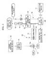
Next, the flow of the refrigerant and the engine-coolant-water in air cooling
operation is explained briefly with reference to the FIG. 2.
In this case, in a 4-way valve 18, spaces are connected between the port D and the
port C, and between the port E and the port S. The discharging side of the compression
device 11 is connected to the outdoor heat exchanging device 12. In this condition, the
high temperature high pressure gas refrigerant discharged from the compression device 11
is sent to the indoor heat exchanging device 12 which functions as a condenser through the
4-way valve 18.
The high temperature high pressure gas refrigerant is evaporated in the outdoor
heat exchanging device 12 to discharge heat to outdoor air; thus, the refrigerant becomes
high temperature high pressure liquid refrigerant. This liquid refrigerant is introduced to
the receiver 15 through the check valve 20. The liquid refrigerant separated into gas and
liquid components in the receiver 15 is introduced to the throttling construction 1b through
the operating valve 21; then the pressure is reduced in the process of passing through the
throttling construction 1b resulting in low temperature low pressure liquid refrigerant, then
the liquid refrigerant is sent to the indoor heat exchanging device 1a which functions as an
evaporator.
The low temperature low pressure liquid refrigerant sent to the indoor heat
exchanging device 1 a removes heat from the indoor air and is evaporated. In this process,
this refrigerant chills the indoor air and becomes low temperature low pressure gas
refrigerant, and is introduced to the 4-way valve 18 through the operating valve 21 and the
refrigerant pipe 2.
The low temperature low pressure gas refrigerant introduced to the 4-way valve
18 flows into the accumulator 14 from the port E via the port S. After the liquid content
is separated here, the gas refrigerant is absorbed in the compression device 11. The gas
refrigerant absorbed by the compression device 11 is compressed by the operation of the
compression device and becomes high temperature high pressure gas refrigerant to be sent
to the outdoor heat exchanging device 12; thus, the refrigerating cycle where the
refrigerant repeatedly changes state can be formed.
Additionally, in air cooling operations, the above exhaust gas heating device 55 is
stopped.
The first embodiment of above exhaust gas heating device is explained with
reference to the drawings as follows. The drawings used in the explanation a feature of
the construction by enlarging a part of FIG. 1.
In the second embodiment shown in FIG. 3, a combustion device for heating
exhaust gas 70 is provided as a exhaust gas heating device exhausted from the gas engine
GE and for increasing quantity of thermal energy collectable in the exhaust gas heat
exchanging device 34.
This combustion device for heating exhaust gas 70 comprises a hollow
combusting device body 71, a combustion nozzle 72 provided in the combusting device
body 71, a fuel supplying system 73 which supplies fuel and air to the combustion nozzle
in a predetermined mixture ratio, a combustion gas supplying channel 94 which supplies
combustion gas generated by combusting the fuel with the combustion nozzle 72, from the
combustor 71 to exhaust gas exhausted from the gas engine GE.
That is, in the combustion device for heating exhaust gas 70, combustion gas
generated by combusting fuel in the combustor 71 is mixed with the exhaust gas
exhausted from the gas engine GE of the gas heat pump type air conditioning device via
combustion gas supplying channel 94 so as to be supplied to the exhaust gas system 50.
In the embodiment shown in the drawing, although the combustion gas supplying
channel 94 joins to a piping of the exhaust system 50 between the gas engine GE and the
exhaust gas heat exchanging device 34, the combustion gas may be supplied directly
inside the exhaust gas heat exchanging device 34.
In the fuel supplying system 73, a control valve 73a is provided, air-fuel mixture
in which fuel and air are mixed in appropriate ratio is supplied to the combustion nozzle
72 via this control valve 73a. The control valve 73a opens when a combustion device for
heating exhaust gas 70 operates, in other words, when an outdoor air temperature
detecting device 74 detects a temperature lower than a predetermined value during air
heating operation and a control signal output from the control section 75 is received. As
an outdoor air temperature detecting device 74, a temperature sensor which can be
provided in an appropriate place near the outdoor unit. Also, as other types of an outdoor
air temperature detecting device. Also, the condition of outdoor air can be determined
depending on the condition of the refrigerant such as temperature and pressure detected by
various sensors which are provided in the channel for circulating the refrigerant.
When a detecting signal indicating a low outdoor temperature is input to the
control section 75, the control section 75 opens the control valve 73a to supply fuel and air
to the combustion nozzle 72, and the air-fuel mixture is ignited in the combustion nozzle
72.
When the air-fuel mixture is combusted, high temperature combustion gas is
generated to be supplied to the exhaust system 50; thus, the thermal energy retained in the
combustion gas is added to the exhaust gas. Because of this, the amount of heat which
can be absorbed in the engine coolant water in the exhaust gas heat exchanging device
increases, and the engine coolant water is more highly heated and can be supplied to the
water heat exchanging device 13. Accordingly, the amount of heat for heating the
refrigerant in the water heat exchanging device 13 increases, and it is possible to evaporate
low temperature low pressure refrigerant even during low outdoor air temperature and to
supply the refrigerant to the refrigerating cycle.
The fuel to be used in above combusting device for heating exhaust gas 70 should
preferably be the gas fuel such as municipal gas which is used similarly as gas engine GE.
This is because the gas engine GE and the fuel system can used compatibly, and
additionally the cost of the fuel is low.
In the third embodiment as shown in the FIG. 4, the combustion nozzle 72 of the
combusting device for heating exhaust gas 70A is provided inside the hollow combustion
device body 71A which can be compatible with the exhaust gas heat exchanging device
34A and the casing. Other factors are similar to the second embodiment as shown in FIG.
3, and the same reference numerals are used and detailed explanation is omitted.
In this combustion device for heating exhaust gas 70A which is constructed in
such a way, the amount of heat of the combustion gas generated inside the combustion
device body 71A is directly added to the exhaust gas passing through the exhaust gas heat
exchanging device 34A by combusting the air-fuel mixture in the combustion nozzle 72.
By doing this, the engine coolant water flowing through the group of pipes 34a can be
heated highly efficiently with no thermal loss, and also, it can be expected that exhaust gas
and engine coolant water are heated by radiated heat from the flame.
In the fourth embodiment shown in FIG. 5, the combustion nozzle 72 of the
combustion device for heating exhaust gas 70B is provided in hollow combusting device
body 71B which is compatible with the catalyst container which contains the exhaust gas
cleaning catalyst 80. Other factors are similar to the third embodiment as shown in FIG.
3, and the same reference numerals are used and detailed explanation is omitted.
The combusting device for heating exhaust gas 70B containing the exhaust gas
cleaning catalyst 80 is provided in the exhaust system 50 to be located between the gas
engine and the exhaust gas heat exchanging device 34. As an exhaust gas cleaning
catalyst 80, for example, a rhodium catalytic converter is preferably used. By
constructing it in this way, it is possible to increase the heat for heating the engine coolant
water at the same time as cleaning the exhaust gas of gas engine GE and the exhaust gas.
Also, it is known that the cleaning of exhaust gas by the exhaust gas cleaning
catalyst 80 can be done more efficiently under conditions in which the exhaust gas is at a
high temperature; therefore, raising the temperature of the exhaust gas by adding
combustion gas can also lead to the promotion of clearing the combustion gas by the
catalyst.
As explained above, the exhaust gas heating device 55 which can heat the exhaust
gas according to necessity during air heating operation is provided; thus, more heat is
added to the waste heat of the engine, and therefore it is possible to supply more thermal
energy to exhaust gas heat exchanging device 34 and the engine coolant water can be
heated to higher temperatures than conventionally.
Because of this, even in cold areas where outdoor air temperature may be quite
low, the refrigerant can be evaporated in the water heat exchanging device 13 by
exchanging heat with high temperature engine coolant water retaining large amounts of
thermal energy. Accordingly, the refrigerating cycle can be maintained by using heat
supplied from the waste heat of the engine and the exhaust gas heating device 55 even
during periods of low outdoor air temperature in which sufficient amounts of heat
necessary to evaporate the refrigerant in outdoor heat exchanging device 12 cannot be
obtained from outdoor air; thus, sufficient air heating operating capacity is obtained, and
air heating capacity can be enhanced even during periods of low outdoor air temperature.
The construction of present invention is not limited to above embodiment, and for
example, factors such as the number or variations of devices relating to the refrigerating
cycle can be preferably changed within the scope of the features of present invention.
Claims (9)
- A gas heat pump type air conditioning device comprising:wherein the refrigerant is heated by the engine-coolant-water to enhance air heating capacity.a compression device (11) having a gas engine as a driving source and forming a refrigerating cycle by circulating a refrigerant;an exhaust gas heat exchanging device (34) which collects waste heat exhausted from the gas engine and returns the heat back to engine-coolant-water; anda heating device (70 ; 70A ; 70B) which heats exhaust gas exhausted from the gas engine so as to increase an amount of thermal energy collectible in the exhaust gas heat exchanging device (34);
- A gas heat pump type air conditioning device according to claim 1, wherein the heating device (70 ; 70A ; 70B) is a combusting device for heating exhaust gas (70) which supplies combustion gas generated by combusting fuel in a combustor (71 ; 71A ; 71B) to the exhaust gas.
- A gas heat pump type air conditioning device according to claim 2, wherein the combustor (71A) of the combusting device for heating exhaust gas (70A) is provided in the exhaust gas heat exchanging device (34A).
- A gas heat pump type air conditioning device according to claim 2, wherein a catalyst container which contains exhaust gas cleaning catalyst (80) is provided in an exhaust system (50) which connects the gas engine and the exhaust gas heat exchanging device (34), and the combustor (71B) for heating exhaust gas (70B) is provided in the catalyst container.
- A gas heat pump type air conditioning device according to claims 1 to 4, wherein the heating device (71 ; 71A ; 71B) is operated when a outdoor air temperature detecting device (74) detects a temperature lower than a predetermined value.
- A gas heat pump type air conditioning device according to claims 2 to 5, wherein the fuel to be combusted in the combustor (71 ; 71A ; 71B) is the same fuel for driving the gas engine.
- A combusting device for heating exhaust gas (70) provided in a channel of exhaust gas exhausted from a gas engine of a gas heat pump type air conditioning device of anyone of claims 1 to 6 so as to heat the exhaust gas comprising:a hollow combustor (71);a combustion nozzle (72) provided in the combustor (71);a fuel system (73) for supplying fuel and air to the combustion nozzle (72) in a predetermined ratio;a combustion gas supplying channel (94) which supplies combustion gas generated by combusting the fuel with the combustion nozzle (72), from the combustor (71) to exhaust gas exhausted from the gas engine of the gas heat pump type air conditioning device.
- A combustion device for heating exhaust gas (70A) provided in a channel of exhaust gas exhausted from a gas engine of a gas heat pump type air conditioning device of anyone of claims 1 to 6 so as to heat the exhaust gas comprising:wherein amount of heat of combustion gas generated in the combustor (71A) by combusting the fuel with the combustion nozzle (72) is added to amount of heat of exhaust gas which is exhausted from the gas engine (GE) of the gas heat pump type air conditioning device and passes through the combustor (71A).a combustor (71A) a hollow casing of which is compatibly used by an exhaust gas heat exchanging device (34A);a combustion nozzle (72) provided in the combustor (71A);a fuel supplying system (73) which supplies fuel and air to the combustion nozzle (72) by a predetermined ratio,
- A combusting device for heating exhaust gas (70B) provided in a channel of exhaust gas exhausted from a gas engine of a gas heat pump type air conditioning device of anyone of claims 1 to 6 so as to heat the exhaust gas comprising:wherein an amount of heat of combustion gas generated in the combustor (71B) by combusting the fuel with the combustion nozzle (72) is added to amount of heat of exhaust gas which is exhausted from the gas engine of the gas heat pump type air conditioning device and passes through the combustor (71B).a combustor (71B) which is compatibly a catalyst container which contains exhaust gas cleaning catalyst (80);a combustion nozzle (72) provided in the combustor (71B);a fuel supplying system (73) which supplies fuel and air to the combustion nozzle (72) by a predetermined ratio,
Applications Claiming Priority (2)
| Application Number | Priority Date | Filing Date | Title |
|---|---|---|---|
| JP2001264908 | 2001-08-31 | ||
| JP2001264908A JP2003075019A (en) | 2001-08-31 | 2001-08-31 | Gas heat pump type air conditioning device and combustion device for heating exhaust gas |
Publications (1)
| Publication Number | Publication Date |
|---|---|
| EP1288591A2 true EP1288591A2 (en) | 2003-03-05 |
Family
ID=19091439
Family Applications (1)
| Application Number | Title | Priority Date | Filing Date |
|---|---|---|---|
| EP02292142A Withdrawn EP1288591A2 (en) | 2001-08-31 | 2002-08-30 | Gas heat pump type air conditioning device, and combustion device for heating exhaust gas |
Country Status (7)
| Country | Link |
|---|---|
| US (1) | US20030041613A1 (en) |
| EP (1) | EP1288591A2 (en) |
| JP (1) | JP2003075019A (en) |
| KR (1) | KR20030019224A (en) |
| CN (1) | CN1170099C (en) |
| CA (1) | CA2398434A1 (en) |
| RU (1) | RU2002123227A (en) |
Cited By (4)
| Publication number | Priority date | Publication date | Assignee | Title |
|---|---|---|---|---|
| EP1628092A2 (en) | 2004-08-17 | 2006-02-22 | Lg Electronics Inc. | Air conditioning system combined with an electricity generating system |
| EP1628103A3 (en) * | 2004-08-17 | 2006-11-08 | Lg Electronics Inc. | Electricity generating and air conditioning system with dehumidifier |
| CN111473479A (en) * | 2020-04-21 | 2020-07-31 | 深圳市英维克科技股份有限公司 | Cooling system control method and related equipment |
| CN112212543A (en) * | 2020-09-30 | 2021-01-12 | 北京金茂绿建科技有限公司 | Heat source tower heat pump system |
Families Citing this family (15)
| Publication number | Priority date | Publication date | Assignee | Title |
|---|---|---|---|---|
| JP2005274412A (en) * | 2004-03-25 | 2005-10-06 | Denso Corp | Temperature sensor integrated pressure sensor device |
| KR100579576B1 (en) * | 2004-08-17 | 2006-05-15 | 엘지전자 주식회사 | Cogeneration System |
| KR100579575B1 (en) * | 2004-08-17 | 2006-05-15 | 엘지전자 주식회사 | Power generation air conditioning system |
| KR100644826B1 (en) * | 2004-12-10 | 2006-11-10 | 엘지전자 주식회사 | Cogeneration System |
| KR100634810B1 (en) * | 2005-07-12 | 2006-10-16 | 엘지전자 주식회사 | Cogeneration System |
| JP5191792B2 (en) * | 2008-05-07 | 2013-05-08 | ヤンマー株式会社 | Cooling water circuit for stationary engine |
| DE102012215551A1 (en) * | 2012-09-03 | 2014-03-06 | Robert Bosch Gmbh | Internal combustion engine |
| US10132507B2 (en) * | 2014-08-20 | 2018-11-20 | Intellihot, Inc. | Combined hot water and air heating and conditioning system including heat pump |
| CN104864648B (en) * | 2015-04-30 | 2017-07-28 | 国家电网公司 | Absorption heat pump reclaims circulating water afterheat overall coefficient of performance on-line monitoring method |
| WO2018148096A1 (en) * | 2017-02-08 | 2018-08-16 | The Delfield Company, Llc | Small refrigerant receiver for use with thermostatic expansion valve refrigeration system |
| KR102075459B1 (en) * | 2017-11-20 | 2020-02-10 | 엘지전자 주식회사 | A gas heat-pump system |
| CN110360767A (en) * | 2019-06-05 | 2019-10-22 | 天津城建大学 | A kind of driving compression heat pump system of flexible gas engine with combustion-compensating device |
| CN110332634A (en) * | 2019-07-08 | 2019-10-15 | 上海嘉熙科技有限公司 | Ultra-thin heat pump type air conditioner system |
| DE102021122082A1 (en) * | 2021-08-26 | 2023-03-02 | Purem GmbH | Exhaust gas heater and method of manufacturing an exhaust gas heater |
| CN120777225B (en) * | 2025-09-03 | 2025-11-11 | 上海环保(集团)有限公司 | An adjustable grate seal structure for heat pumps and a method for adjusting axial force. |
Family Cites Families (7)
| Publication number | Priority date | Publication date | Assignee | Title |
|---|---|---|---|---|
| US4366674A (en) * | 1980-06-06 | 1983-01-04 | Caterpillar Tractor Co. | Internal combustion engine with Rankine bottoming cycle |
| JPS60122214A (en) * | 1983-11-30 | 1985-06-29 | Tokyo Roki Kk | Method and device for removing black smoke from exhaust gas of internal combustion engine |
| JPH08261598A (en) * | 1995-03-22 | 1996-10-11 | Mitsubishi Heavy Ind Ltd | Engine-driven type air conditioner |
| JPH11132419A (en) * | 1997-11-04 | 1999-05-21 | Osaka Gas Co Ltd | Burner |
| JPH11248287A (en) * | 1998-03-04 | 1999-09-14 | Mitsubishi Heavy Ind Ltd | Gas engine system; outdoor unit and air conditioner |
| JPH11316062A (en) * | 1998-05-06 | 1999-11-16 | Mitsubishi Heavy Ind Ltd | Outdoor machine unit and air conditioner |
| JP2001227330A (en) * | 2000-02-21 | 2001-08-24 | Osaka Gas Co Ltd | Engine system |
-
2001
- 2001-08-31 JP JP2001264908A patent/JP2003075019A/en active Pending
-
2002
- 2002-08-05 US US10/211,545 patent/US20030041613A1/en not_active Abandoned
- 2002-08-16 CA CA002398434A patent/CA2398434A1/en not_active Abandoned
- 2002-08-23 CN CNB021301468A patent/CN1170099C/en not_active Expired - Fee Related
- 2002-08-28 RU RU2002123227/06A patent/RU2002123227A/en unknown
- 2002-08-30 KR KR1020020051781A patent/KR20030019224A/en not_active Abandoned
- 2002-08-30 EP EP02292142A patent/EP1288591A2/en not_active Withdrawn
Cited By (6)
| Publication number | Priority date | Publication date | Assignee | Title |
|---|---|---|---|---|
| EP1628092A2 (en) | 2004-08-17 | 2006-02-22 | Lg Electronics Inc. | Air conditioning system combined with an electricity generating system |
| EP1628103A3 (en) * | 2004-08-17 | 2006-11-08 | Lg Electronics Inc. | Electricity generating and air conditioning system with dehumidifier |
| US7305840B2 (en) | 2004-08-17 | 2007-12-11 | Lg Electronics Inc. | Electricity generating and air conditioning system with dehumidifier |
| EP1628092A3 (en) * | 2004-08-17 | 2011-06-15 | LG Electronics, Inc. | Air conditioning system combined with an electricity generating system |
| CN111473479A (en) * | 2020-04-21 | 2020-07-31 | 深圳市英维克科技股份有限公司 | Cooling system control method and related equipment |
| CN112212543A (en) * | 2020-09-30 | 2021-01-12 | 北京金茂绿建科技有限公司 | Heat source tower heat pump system |
Also Published As
| Publication number | Publication date |
|---|---|
| CN1170099C (en) | 2004-10-06 |
| CN1403767A (en) | 2003-03-19 |
| US20030041613A1 (en) | 2003-03-06 |
| CA2398434A1 (en) | 2003-02-28 |
| JP2003075019A (en) | 2003-03-12 |
| RU2002123227A (en) | 2004-03-10 |
| KR20030019224A (en) | 2003-03-06 |
Similar Documents
| Publication | Publication Date | Title |
|---|---|---|
| US6735969B2 (en) | Gas heat pump type air conditioning device, engine-coolant-water heating device, and operating method for gas heat pump type air conditioning device | |
| EP1288591A2 (en) | Gas heat pump type air conditioning device, and combustion device for heating exhaust gas | |
| EP1288593A2 (en) | Gas heat pump type air conditioning device | |
| US12392527B2 (en) | Ejector-enhanced heat recovery refrigeration system | |
| US5729985A (en) | Air conditioning apparatus and method for air conditioning | |
| US6883342B2 (en) | Multiform gas heat pump type air conditioning system | |
| JPH02263073A (en) | Freezing device for transportation engine and method for improving capacity of heating cycle | |
| AU8550601A (en) | Outdoor heat exchanger unit, outdoor unit, and gas heat pump type air conditioner | |
| CN101818969A (en) | Water circulation system with cold-producing medium circulation interlock | |
| KR101944831B1 (en) | Gas heat pump | |
| US4612782A (en) | Twin reservoir heat transfer circuit | |
| WO1993002328A1 (en) | Refrigeration and air conditioning system for vehicles | |
| JP2000028186A (en) | Air conditioner | |
| JP3600906B2 (en) | Air conditioner | |
| JP2006234321A (en) | Outdoor unit and air conditioner | |
| JP4773637B2 (en) | Multi-type gas heat pump type air conditioner | |
| KR102044308B1 (en) | Gas engine-driven heat pump type air conditioning and hot water suppling apparatus | |
| JP2002162109A (en) | Hot water supply system | |
| JPH0820139B2 (en) | Heat storage type heat pump device | |
| JPH07280385A (en) | Heat pump device | |
| JPH10306954A (en) | Engine driven refrigerant compression circulation heat transfer device | |
| CN118457157A (en) | Thermal management systems and vehicles | |
| JPH08233404A (en) | Air conditioner | |
| JPH01296056A (en) | Heat-pump type air conditioner | |
| JPH07198226A (en) | Exhaust device for air conditioner |
Legal Events
| Date | Code | Title | Description |
|---|---|---|---|
| PUAI | Public reference made under article 153(3) epc to a published international application that has entered the european phase |
Free format text: ORIGINAL CODE: 0009012 |
|
| AK | Designated contracting states |
Kind code of ref document: A2 Designated state(s): AT BE BG CH CY CZ DE DK EE ES FI FR GB GR IE IT LI LU MC NL PT SE SK TR Designated state(s): AT BE BG CH CY CZ DE DK EE ES FI FR GB GR IE IT LI LU MC NL PT SE SK TR |
|
| AX | Request for extension of the european patent |
Extension state: AL LT LV MK RO SI |
|
| STAA | Information on the status of an ep patent application or granted ep patent |
Free format text: STATUS: THE APPLICATION IS DEEMED TO BE WITHDRAWN |
|
| 18D | Application deemed to be withdrawn |
Effective date: 20070301 |