EP1288550A1 - Electromagnetic valve - Google Patents
Electromagnetic valve Download PDFInfo
- Publication number
- EP1288550A1 EP1288550A1 EP02256028A EP02256028A EP1288550A1 EP 1288550 A1 EP1288550 A1 EP 1288550A1 EP 02256028 A EP02256028 A EP 02256028A EP 02256028 A EP02256028 A EP 02256028A EP 1288550 A1 EP1288550 A1 EP 1288550A1
- Authority
- EP
- European Patent Office
- Prior art keywords
- magnetic
- valve
- opening
- recessed portions
- magnetic case
- Prior art date
- Legal status (The legal status is an assumption and is not a legal conclusion. Google has not performed a legal analysis and makes no representation as to the accuracy of the status listed.)
- Granted
Links
- 230000005291 magnetic effect Effects 0.000 claims abstract description 102
- 238000005520 cutting process Methods 0.000 claims abstract description 31
- XEEYBQQBJWHFJM-UHFFFAOYSA-N Iron Chemical group [Fe] XEEYBQQBJWHFJM-UHFFFAOYSA-N 0.000 claims description 45
- 230000005284 excitation Effects 0.000 claims description 5
- 230000008878 coupling Effects 0.000 description 13
- 238000010168 coupling process Methods 0.000 description 13
- 238000005859 coupling reaction Methods 0.000 description 13
- 239000012530 fluid Substances 0.000 description 5
- 238000003825 pressing Methods 0.000 description 4
- 238000013459 approach Methods 0.000 description 3
- 210000000078 claw Anatomy 0.000 description 3
- 230000000149 penetrating effect Effects 0.000 description 3
- 230000000694 effects Effects 0.000 description 2
- 238000000034 method Methods 0.000 description 2
- 238000004513 sizing Methods 0.000 description 2
- 238000003466 welding Methods 0.000 description 2
- 239000000470 constituent Substances 0.000 description 1
- 239000003302 ferromagnetic material Substances 0.000 description 1
- 238000004519 manufacturing process Methods 0.000 description 1
- 229920003002 synthetic resin Polymers 0.000 description 1
- 239000000057 synthetic resin Substances 0.000 description 1
Images



Classifications
-
- F—MECHANICAL ENGINEERING; LIGHTING; HEATING; WEAPONS; BLASTING
- F16—ENGINEERING ELEMENTS AND UNITS; GENERAL MEASURES FOR PRODUCING AND MAINTAINING EFFECTIVE FUNCTIONING OF MACHINES OR INSTALLATIONS; THERMAL INSULATION IN GENERAL
- F16K—VALVES; TAPS; COCKS; ACTUATING-FLOATS; DEVICES FOR VENTING OR AERATING
- F16K31/00—Actuating devices; Operating means; Releasing devices
- F16K31/02—Actuating devices; Operating means; Releasing devices electric; magnetic
- F16K31/06—Actuating devices; Operating means; Releasing devices electric; magnetic using a magnet, e.g. diaphragm valves, cutting off by means of a liquid
-
- F—MECHANICAL ENGINEERING; LIGHTING; HEATING; WEAPONS; BLASTING
- F16—ENGINEERING ELEMENTS AND UNITS; GENERAL MEASURES FOR PRODUCING AND MAINTAINING EFFECTIVE FUNCTIONING OF MACHINES OR INSTALLATIONS; THERMAL INSULATION IN GENERAL
- F16K—VALVES; TAPS; COCKS; ACTUATING-FLOATS; DEVICES FOR VENTING OR AERATING
- F16K31/00—Actuating devices; Operating means; Releasing devices
- F16K31/02—Actuating devices; Operating means; Releasing devices electric; magnetic
- F16K31/06—Actuating devices; Operating means; Releasing devices electric; magnetic using a magnet, e.g. diaphragm valves, cutting off by means of a liquid
- F16K31/0603—Multiple-way valves
- F16K31/0624—Lift valves
- F16K31/0627—Lift valves with movable valve member positioned between seats
-
- F—MECHANICAL ENGINEERING; LIGHTING; HEATING; WEAPONS; BLASTING
- F16—ENGINEERING ELEMENTS AND UNITS; GENERAL MEASURES FOR PRODUCING AND MAINTAINING EFFECTIVE FUNCTIONING OF MACHINES OR INSTALLATIONS; THERMAL INSULATION IN GENERAL
- F16K—VALVES; TAPS; COCKS; ACTUATING-FLOATS; DEVICES FOR VENTING OR AERATING
- F16K31/00—Actuating devices; Operating means; Releasing devices
- F16K31/02—Actuating devices; Operating means; Releasing devices electric; magnetic
- F16K31/06—Actuating devices; Operating means; Releasing devices electric; magnetic using a magnet, e.g. diaphragm valves, cutting off by means of a liquid
- F16K31/0644—One-way valve
- F16K31/0655—Lift valves
-
- Y—GENERAL TAGGING OF NEW TECHNOLOGICAL DEVELOPMENTS; GENERAL TAGGING OF CROSS-SECTIONAL TECHNOLOGIES SPANNING OVER SEVERAL SECTIONS OF THE IPC; TECHNICAL SUBJECTS COVERED BY FORMER USPC CROSS-REFERENCE ART COLLECTIONS [XRACs] AND DIGESTS
- Y10—TECHNICAL SUBJECTS COVERED BY FORMER USPC
- Y10T—TECHNICAL SUBJECTS COVERED BY FORMER US CLASSIFICATION
- Y10T137/00—Fluid handling
- Y10T137/598—With repair, tapping, assembly, or disassembly means
- Y10T137/5987—Solenoid or electromagnetically operated valve
-
- Y—GENERAL TAGGING OF NEW TECHNOLOGICAL DEVELOPMENTS; GENERAL TAGGING OF CROSS-SECTIONAL TECHNOLOGIES SPANNING OVER SEVERAL SECTIONS OF THE IPC; TECHNICAL SUBJECTS COVERED BY FORMER USPC CROSS-REFERENCE ART COLLECTIONS [XRACs] AND DIGESTS
- Y10—TECHNICAL SUBJECTS COVERED BY FORMER USPC
- Y10T—TECHNICAL SUBJECTS COVERED BY FORMER US CLASSIFICATION
- Y10T137/00—Fluid handling
- Y10T137/8593—Systems
- Y10T137/86493—Multi-way valve unit
- Y10T137/86574—Supply and exhaust
- Y10T137/86622—Motor-operated
Definitions
- the present invention relates to an electromagnetic valve comprising a solenoid portion and a valve portion, and in particular to an electromagnetic valve suitable for small-sizing.
- a known electromagnetic valve is disclosed in JU-A 06-071980.
- the electromagnetic valve has a solenoid portion provided in a cover with one open end and comprising a magnetic frame with a bobbin on which a coil is wound, a fixed iron core mounted in a central hole of the bobbin, a magnetic plate arranged on one side of the bobbin, a movable iron core slidably inserted in the central hole of the bobbin and a central hole of the magnetic plate, and a return spring for biasing the movable iron core.
- the valve also has a valve portion comprising a main valve body with a plurality of ports, a valve seat in a passage causing these ports to communicate with one another, and a valve member driven by the movable iron core to open/close the valve seat.
- the solenoid portion and the valve portion are coupled relative to each other by engaging a claw portion provided in a projecting manner on a side wall of the valve portion and an engagement window provided in a penetrating manner on a side of an opening of the cover with each other and causing the resilient force of a leaf spring provided on a bottom side of the magnetic frame to act on the engaged claw portion and window.
- An electromagnetic valve comprises a solenoid portion where a movable iron core driven by excitation operation to a coil is provided in a magnetic case having an opening at one end and a valve portion where a valve member which is driven by the movable iron core to switch flow paths among a plurality of ports is provided in a valve body, and where the solenoid portion and the valve portion are coupled to each other by fitting one end of the valve body into the opening of the magnetic case.
- Recessed portions for engagement are provided on opposing side faces of the valve body at the end of the valve body which connects with the solenoid portion .
- Inner wall faces of the recessed portions on the solenoid portion side are formed as an inclining face from the solenoid portion side to the other end side thereof towards a depth direction.
- Cuttings for forming caulking pieces are formed on a side wall of the magnetic case positioned on the side of the opening at positions corresponding to the recessed portions.
- the valve portion and the solenoid portion are coupled to each other in a state that the valve portion and the solenoid portion have been biased in a direction in which they are fitted to each other by causing the caulking pieces to abut on the inclining faces of the recessed portions to caulk the caulking pieces into the recessed portions.
- the solenoid portion by positioning a magnetic plate relative to the magnetic case such that a distance between a magnetic pole face of a fixed magnetic pole member which magnetically attracts the movable iron core and which is formed in the magnetic case and a face of the magnetic plate which is positioned at the opening of the magnetic case is fixed and securing the magnetic plate to the side wall of the magnetic case.
- the cuttings may be formed in a U-shape opening towards the opening of the magnetic case and a region surrounded by the U-shape cutting is caulked into the recessed portion as the caulking piece.
- the cutting may be formed as a straight line parallel with the end of the side wall at the opening of the magnetic case and a region positioned between the cutting and the opening of the magnetic case is caulked into the recessed portion as the caulking piece.
- the cutting is formed as a thin hole extending in parallel with the opening of the magnetic case and a region positioned between the thin hole and the opening of the magnetic case is caulked into the recessed portion as the caulking piece.
- the valve portion and the solenoid portion are coupled in a state where they have been biased in the directions in which they are fitted to each other by providing a recessed portion for engagement on opposite faces of the valve body, forming an inner wall face of the recessed portions on the solenoid portion side as an inclining face inclined from the solenoid portion side to the other side in the depth direction, and forming a caulking piece at a location of the magnetic case corresponding to the recessed portion and causing the caulking piece to abut on the inclining face of the recessed portion to caulk it therein, the structure of the solenoid portion is simplified over that of the known valve, and coupling of the solenoid to the valve portion can be performed more simply and more stably. In addition, the coupling strength can be secured simply at a low cost without making the solenoid portion large.
- the solenoid portion When the solenoid portion is formed by positioning the magnetic plate relative to the magnetic case in the state where the fixed iron core is pressure-contacted to the inner end of the magnetic case such that the distance between the end face of the fixed iron core on the side of the movable iron core and the face of the magnetic plate positioned at the opening of the magnetic case is fixed and fixing the magnetic plate to the side wall of the magnetic case, assembling of the solenoid portion itself can be performed with a high accuracy and simultaneously positioning between the solenoid portion and the valve portion can be performed stably and accurately.
- FIG. 1(a) to 1(c) A first embodiment of an electromagnetic valve is shown in Figs. 1(a) to 1(c) and comprises a solenoid portion 10 and a valve portion 20.
- the solenoid portion 10 is constituted by a bobbin 13 on which a coil 12 has been wound, a magnetic case 11 which comprises a side wall with a generally rectangular cross-sectional shape provided around the coil 12 and an end wall formed integrally with the side wall and which has opening at its one end, a magnetic plate 16 which is disposed to the bobbin 13 on the side of the opening of the magnetic plate 11, a movable iron core 15 which is formed in a column shape with a generally oval or elliptic sectional shape and whose one end is fitted from the magnetic plate 16 side slidably into a central hole penetrating the magnetic plate 16 and the bobbin 13, and a fixed iron core 14 (a fixed magnetic pole member) which is formed in a column shape with a generally oval or elliptic sectional shape, which is disposed on an end face of the magnetic case 11 to be inserted in the central hole of the bobbin 13, and which is provided with an end face attracting one end side of the movable iron core 15 by a magnetic force,
- a magnetic path is formed around the coil 12 of the bobbin 13. Also, a stopper 17 which is made from synthetic resin and which abuts on the magnetic plate 16 when the movable iron core 15 is attracted to the fixed iron core 14 is press-fitted into the movable iron core 14 on its valve portion side, and a return spring 18 is confined between a flange portion at a periphery of the stopper 17 and the magnetic plate 16.
- the work stand 30 has a base portion 31, a first core portion 32 which is provided at a center of the base portion in a standing manner to match with an inner diameter of the magnetic case 11, and a second core portion 33 which is provided at a center of the first core portion 32 to match with an inner diameter of the central hole penetrating the bobbin 13 and the magnetic plate 16, and the length of the second core portion 33 is formed in a length L defining an end face of the fixed iron core 14 (the fixed magnetic pole member) inserted into the central hole of the bobbin, or the magnetic pole face, and a face of the magnetic plate 16 positioned on the opening side of the magnetic case 11.
- the magnetic plate 16, the bobbin 13, the fixed iron core 14 and the magnetic case 11 are set on the work stand 30 by fitting the second core portion 33 into the central hole of the magnetic plate 16 and placing the magnetic plate 16 on an upper face of the first core portion 32, by fitting the central hole of the bobbin 13 on the second core portion 33 and placing the bobbin 13 on the magnetic plate 16 and causing an end face of the fixed iron core 14 inserted into the central hole abut on a top face of the second core portion 33 like the above, and finally by fitting the opening portion of the magnetic case 11 to the first core portion 32 so as to align therewith (refer to Fig. 2(a)).
- an outer face of the end face of the magnetic case 11 is pressed by means of a pressing member 40 and an end face of the fixed iron core 14 is pressed against a top face of the second core portion 33 so that the magnetic plate 16 is positioned accurately relative to the magnetic case 11 such that the distance between the end face of the fixed iron core 14 and the a face of the magnetic plate 16 positioned on the side of the opening of the magnetic case 11 becomes the L in a state where the fixed iron core 14 has been brought into contact the inner end of the magnetic case 11 in a pressed manner.
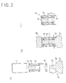
- an outer periphery of the magnetic plate 16 is fixed to the side wall of the magnetic case 11 by such means as welding or the like (refer to Fig. 2(b)), and the solenoid portion 10 (refer to Fig. 2(c)) is completed via these steps.
- the distance between the end face of the fixed iron core 14 and the face of the magnetic plate 16 positioned on the opening side of the magnetic case 11 can be maintained at the defined value L accurately.
- variations in the distance L can be suppressed, so that, even when the movable iron core 15 is attracted to the end face of the fixed iron core 14 and the stopper 17 abuts on the magnetic plate 16, a position relationship between the end face of the fixed iron core 14 in the central hole and the end face of the movable iron core 15 can be maintained properly.
- the valve portion 20 comprises a valve body 21 with a generally rectangular cross-sectional shape formed therein with an input port P, an output port A, a discharge port R and a valve chamber 21a which causes these ports to communicate with one another mutually, a movable orifice 26 and a poppet valve 23 accommodated in the valve chamber 21a, and a push rod 22 which is coupled to the poppet valve 23 and which is pressed by the movable iron core 15.
- the movable orifice 26 is constituted by a supply valve seat 25 which approaches to/separates from the poppet valve 23 to open/close the valve chamber 21a and a pipe passage 26a which causes the input port P and the supply valve seat 25 to communicate with each other and which provides a first acting face 26b and a second acting face 26c for causing the fluid pressure from the input port P in a direction of the poppet valve 23 and in a direction opposed thereto, and the movable orifice is provided in the valve chamber 21a so as to be movable slidably in directions of approaching to/separating from the poppet valve 23.
- the firs acting face 26b has a fluid pressure acting area larger than that of the second acting face 26c on which the fluid pressure acts in the opposing direction.
- the poppet valve 23 is disposed to be movable between the discharge valve seat 24 formed at a position where the discharge port R communicates with the valve chamber 21a and the supply valve seat 25, and it opens/close the both valves according to operation of the solenoid portion 10.
- a poppet spring 23a is confined between the movable orifice 26 and the poppet valve 23. Also, a mouth portion 27 opened in the valve body 21 for inserting the movable orifice 26, the poppet valve 23 and the like in the valve chamber 21a is closed by a bush 28 attached on its periphery with a seal member 29 in an air-tight manner.
- the fluid pressure of fluid supplied from the input port P acts on the both acting faces 26b, 26c of the pipe passage 26a and the movable orifice 26 slides in the direction of the poppet valve 23 due to a differential pressure between pressures on both the faces to cause the supply valve seat 15a to approach to the poppet valve 16. That is, the poppet valve 16 and the movable orifice 16 approach to each other to close the supply valve seat 15a.
- valve portion 20 and the solenoid portion 10 are coupled to each other by fitting to the opening of the magnetic case 11 formed in the generally rectangular cross-sectional shape one end side of the valve body 21 formed in the generally rectangular cross-sectional shape like this, from which the push rod 22 projects and caulking pieces 11b provided on the side wall of the magnetic case 11 which is positioned on the opening side to recessed portions 21b provided on at least one pair of opposing side faces of the valve body 21 which is positioned on the one end side.
- the recessed portion 21b has a sectional shape such as shown in Fig. 1(c) and Fig. 3, namely, an inner wall face 21c positioned on the one end side of the valve body 21 is formed by an inclining face inclining in a direction of the bottom of the recessed portion 21b towards the other end side of the valve body 21, and the section of the recessed portion 21b is entirely formed in a generally trapezoidal shape and a stepped portion 21d is formed on the other end side of the recessed portion 21b.
- Fig. 1(c) and Fig. 3 namely, an inner wall face 21c positioned on the one end side of the valve body 21 is formed by an inclining face inclining in a direction of the bottom of the recessed portion 21b towards the other end side of the valve body 21, and the section of the recessed portion 21b is entirely formed in a generally trapezoidal shape and a stepped portion 21d is formed on the other end side of the recessed portion 21b.
- the valve body 21 is fitted to the magnetic case 11, U-shaped cuttings 11a opened to the opening end side of the side wall are provided at positions of the magnetic case 11 corresponding to the recessed portions 21b of the side wall, and the cuttings 11a, namely, regions which are each surrounded by a first cutting line 11d generally parallel to the opening end of the side wall and two second cutting lines lie provided from both ends of the first cutting line towards the opening end generally perpendicularly thereto form the caulking pieces 11b.
- a region surrounded by the caulking piece 11b and the opening end of the side wall is supported by the stepped portion 21d of the valve body 21.
- Figs. 5 show a second embodiment of an electromagnetic valve according to the present invention, where straight line cuttings 11f which are generally parallel with the opening end of the side wall are provided at positions corresponding to the recessed portions 21b in the side wall of the magnetic case 11 when the valve body 21 is fitted to the magnetic case 11, and regions positioned between the cuttings 11f and the opening end of the side wall form caulking pieces 11g.
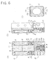
- Fig. 6 shows a third embodiment of an electromagnetic valve according to the present invention, where straight line cuttings 11h, each comprising a thin hole generally parallel with the opening end of the side wall, are generally parallel with the opening end of the side wall are provided at positions corresponding to the recessed portions 21b in the side wall of the magnetic case 11 when the valve body 21 is fitted to the magnetic case 11, and regions positioned between the cuttings 11h and the opening end of the side wall form caulking pieces 11j.
- the magnetic case 11 is opened at one end and it is closed at the other end by an end wall formed integrally with the side wall, but an opening may also be provided at the other end with that second opening being closed by a bottom lid made of ferromagnetic material.
- the cross-sectional shape of the magnetic case 11 is not limited to the depicted generally rectangular shape and it may have other shapes such as a circular shape.
- the movable iron core and the fixed iron core have each been formed of a column with a nearly elliptical cross-section but again they may be made in other shapes.
- the shape of the central hole is of course one matching with the sectional shape of each iron core.
- the fixed iron core serving as the fixed magnetic pole member has been fitted and fixed in the central hole, but the fixed magnetic pole member is not necessarily, provided with the iron core portion fitted into the central hole and it may instead be a plate-shaped one closing the end portion of the central hole.
- the recessed portions which are positioned at one end and opposite sides of the valve body and whose inner wall faces are formed by the inclining faces which incline from the one end of the valve body to the other end towards its depth, the cuttings for forming the caulking pieces which are provided at positions corresponding to the recessed portions on the walls to the sides of the opening of the magnetic case, and coupling of the valve portion and the solenoid portion to each other in the state where they have been biased in directions in which they are fitted to each other by causing the caulking pieces to abut on the inclining faces of the recessed portions to caulk them in the recessed portions, mean that a high coupling strength between the valve portion and the solenoid portion can be secured simply at a low cost without large-sizing the solenoid portion.
Landscapes
- Engineering & Computer Science (AREA)
- General Engineering & Computer Science (AREA)
- Mechanical Engineering (AREA)
- Magnetically Actuated Valves (AREA)
Abstract
Description
- The present invention relates to an electromagnetic valve comprising a solenoid portion and a valve portion, and in particular to an electromagnetic valve suitable for small-sizing.
- A known electromagnetic valve is disclosed in JU-A 06-071980. The electromagnetic valve has a solenoid portion provided in a cover with one open end and comprising a magnetic frame with a bobbin on which a coil is wound, a fixed iron core mounted in a central hole of the bobbin, a magnetic plate arranged on one side of the bobbin, a movable iron core slidably inserted in the central hole of the bobbin and a central hole of the magnetic plate, and a return spring for biasing the movable iron core. The valve also has a valve portion comprising a main valve body with a plurality of ports, a valve seat in a passage causing these ports to communicate with one another, and a valve member driven by the movable iron core to open/close the valve seat. The solenoid portion and the valve portion are coupled relative to each other by engaging a claw portion provided in a projecting manner on a side wall of the valve portion and an engagement window provided in a penetrating manner on a side of an opening of the cover with each other and causing the resilient force of a leaf spring provided on a bottom side of the magnetic frame to act on the engaged claw portion and window.
- Since the above described known electromagnetic valve requires a complicated structure where the resilient force due to the leaf spring is caused to act on the engaged portion of the claw portion and the engagement window for coupling the solenoid portion and the valve portion, the size and cost is increased. In addition, assembling and manufacturing must be performed so as to maintain a relatively accurate positional relationship between the movable iron core in the solenoid portion and the part to be driven in the valve portion. For this reason, it is necessary to perform assembling of the solenoid portion itself with a high accuracy and simultaneously perform positioning between the solenoid portion and the valve portion stably and accurately. It is also necessary to obtain sufficient coupling strength with a simple structure.
- The above described problems with the known electromagnetic valve means that it would be desirable to simplify the structure of the solenoid portion and to allow assembling and coupling of the solenoid portion to the valve portion more simply and more stably.
- It would also be desirable to provide an electromagnetic valve where a strong coupling of the valve portion and the solenoid portion can be achieved simply at low cost without having to make the solenoid portion large.
- An electromagnetic valve according to the present invention comprises a solenoid portion where a movable iron core driven by excitation operation to a coil is provided in a magnetic case having an opening at one end and a valve portion where a valve member which is driven by the movable iron core to switch flow paths among a plurality of ports is provided in a valve body, and where the solenoid portion and the valve portion are coupled to each other by fitting one end of the valve body into the opening of the magnetic case. Recessed portions for engagement are provided on opposing side faces of the valve body at the end of the valve body which connects with the solenoid portion . Inner wall faces of the recessed portions on the solenoid portion side are formed as an inclining face from the solenoid portion side to the other end side thereof towards a depth direction. Cuttings for forming caulking pieces are formed on a side wall of the magnetic case positioned on the side of the opening at positions corresponding to the recessed portions. The valve portion and the solenoid portion are coupled to each other in a state that the valve portion and the solenoid portion have been biased in a direction in which they are fitted to each other by causing the caulking pieces to abut on the inclining faces of the recessed portions to caulk the caulking pieces into the recessed portions.
- It is desirable to construct the solenoid portion by positioning a magnetic plate relative to the magnetic case such that a distance between a magnetic pole face of a fixed magnetic pole member which magnetically attracts the movable iron core and which is formed in the magnetic case and a face of the magnetic plate which is positioned at the opening of the magnetic case is fixed and securing the magnetic plate to the side wall of the magnetic case.
- The cuttings may be formed in a U-shape opening towards the opening of the magnetic case and a region surrounded by the U-shape cutting is caulked into the recessed portion as the caulking piece. Alternatively the cutting may be formed as a straight line parallel with the end of the side wall at the opening of the magnetic case and a region positioned between the cutting and the opening of the magnetic case is caulked into the recessed portion as the caulking piece. In a further alternative the cutting is formed as a thin hole extending in parallel with the opening of the magnetic case and a region positioned between the thin hole and the opening of the magnetic case is caulked into the recessed portion as the caulking piece.
- In the electromagnetic valve having the above described arrangement since the valve portion and the solenoid portion are coupled in a state where they have been biased in the directions in which they are fitted to each other by providing a recessed portion for engagement on opposite faces of the valve body, forming an inner wall face of the recessed portions on the solenoid portion side as an inclining face inclined from the solenoid portion side to the other side in the depth direction, and forming a caulking piece at a location of the magnetic case corresponding to the recessed portion and causing the caulking piece to abut on the inclining face of the recessed portion to caulk it therein, the structure of the solenoid portion is simplified over that of the known valve, and coupling of the solenoid to the valve portion can be performed more simply and more stably. In addition, the coupling strength can be secured simply at a low cost without making the solenoid portion large.
- When the solenoid portion is formed by positioning the magnetic plate relative to the magnetic case in the state where the fixed iron core is pressure-contacted to the inner end of the magnetic case such that the distance between the end face of the fixed iron core on the side of the movable iron core and the face of the magnetic plate positioned at the opening of the magnetic case is fixed and fixing the magnetic plate to the side wall of the magnetic case, assembling of the solenoid portion itself can be performed with a high accuracy and simultaneously positioning between the solenoid portion and the valve portion can be performed stably and accurately.
- The invention will now be described by way of example with reference to the accompanying drawings in which:
- Figs. 1 show a first embodiment of an electromagnetic valve according to the present invention, Fig. 1(a) being a longitudinal sectional view in which the left half shows the state at a time of de-excitation of a coil and the right half shows the state at a time of excitation of the coil, Fig. 1(b) being a side view, and Fig. 1(c) being an enlarged partial sectional view of a caulking portion.
- From Figs. 2(a) to (c) are sectional views for explaining the steps for assembling a solenoid portion of the first embodiment of the electromagnetic valve.
- Fig. 3 is an enlarged partial sectional view for explaining a method of coupling a valve portion and a solenoid portion of the first embodiment of the electromagnetic valve effected by caulking.
- Fig. 4 is a cross-sectional view for explaining the method of coupling the valve portion and the solenoid portion of the first embodiment of the electromagnetic valve by caulking.
- Figs. 5 show a second embodiment of an electromagnetic valve according to the present invention, Fig. 5(a) being a longitudinal sectional view in which the left half shows the state at a time of de-excitation of a coil and the right half shows the state at a time of excitation of the coil, Fig. 5(b) being a side view and Fig. 5(c) being a cross-sectional view taken along line I-I.
- Figs . 6 show a third embodiment of an electromagnetic valve according to the present invention, Fig. 6(a) being a longitudinal sectional view in which the left half shows the state at a time of de-excitation of a coil and the right half shows the state at a time of excitation of the coil, Fig. 6(b) being a partial sectional side view and Fig. 6(c) being a cross-sectional view taken along line II-II.
-
- A first embodiment of an electromagnetic valve is shown in Figs. 1(a) to 1(c) and comprises a
solenoid portion 10 and avalve portion 20. - The
solenoid portion 10 is constituted by abobbin 13 on which acoil 12 has been wound, amagnetic case 11 which comprises a side wall with a generally rectangular cross-sectional shape provided around thecoil 12 and an end wall formed integrally with the side wall and which has opening at its one end, amagnetic plate 16 which is disposed to thebobbin 13 on the side of the opening of themagnetic plate 11, amovable iron core 15 which is formed in a column shape with a generally oval or elliptic sectional shape and whose one end is fitted from themagnetic plate 16 side slidably into a central hole penetrating themagnetic plate 16 and thebobbin 13, and a fixed iron core 14 (a fixed magnetic pole member) which is formed in a column shape with a generally oval or elliptic sectional shape, which is disposed on an end face of themagnetic case 11 to be inserted in the central hole of thebobbin 13, and which is provided with an end face attracting one end side of themovable iron core 15 by a magnetic force, i.e., a magnetic pole face. Thebobbin 13 and the fixediron core 14 are fixed in themagnetic case 11 by fixing an outer periphery of themagnetic plate 16 to the side wall of themagnetic case 11 by means of welding or the like. - Thereby, a magnetic path is formed around the
coil 12 of thebobbin 13. Also, astopper 17 which is made from synthetic resin and which abuts on themagnetic plate 16 when themovable iron core 15 is attracted to the fixediron core 14 is press-fitted into themovable iron core 14 on its valve portion side, and areturn spring 18 is confined between a flange portion at a periphery of thestopper 17 and themagnetic plate 16. - In the solenoid portion, when the
coil 12 is put in a de-excited state, as shown on a left half in Fig. 1(a), themovable iron core 14 is moved by a biasing force of thereturn spring 18 in a direction of separating from thefixed iron core 14 or in a direction of pushing apush rod 22 of thevalve portion 20 described later. On the other hand, when thecoil 12 is excited, as shown on a right half in Fig. 1(a), themovable iron core 15 is attracted to the fixediron core 14 against the biasing force of thereturn spring 18 by a magnetic force so that the pushing force of themovable iron core 15 to thepush rod 22 is released. - As steps for assembling the
solenoid portion 10, as shown in Fig. 2, constituent elements of thesolenoid portion 10 is set on a work stand 30. Thework stand 30 has abase portion 31, afirst core portion 32 which is provided at a center of the base portion in a standing manner to match with an inner diameter of themagnetic case 11, and asecond core portion 33 which is provided at a center of thefirst core portion 32 to match with an inner diameter of the central hole penetrating thebobbin 13 and themagnetic plate 16, and the length of thesecond core portion 33 is formed in a length L defining an end face of the fixed iron core 14 (the fixed magnetic pole member) inserted into the central hole of the bobbin, or the magnetic pole face, and a face of themagnetic plate 16 positioned on the opening side of themagnetic case 11. - Next, the
magnetic plate 16, thebobbin 13, thefixed iron core 14 and themagnetic case 11 are set on the work stand 30 by fitting thesecond core portion 33 into the central hole of themagnetic plate 16 and placing themagnetic plate 16 on an upper face of thefirst core portion 32, by fitting the central hole of thebobbin 13 on thesecond core portion 33 and placing thebobbin 13 on themagnetic plate 16 and causing an end face of the fixediron core 14 inserted into the central hole abut on a top face of thesecond core portion 33 like the above, and finally by fitting the opening portion of themagnetic case 11 to thefirst core portion 32 so as to align therewith (refer to Fig. 2(a)). - Then, an outer face of the end face of the
magnetic case 11 is pressed by means of apressing member 40 and an end face of the fixediron core 14 is pressed against a top face of thesecond core portion 33 so that themagnetic plate 16 is positioned accurately relative to themagnetic case 11 such that the distance between the end face of thefixed iron core 14 and the a face of themagnetic plate 16 positioned on the side of the opening of themagnetic case 11 becomes the L in a state where thefixed iron core 14 has been brought into contact the inner end of themagnetic case 11 in a pressed manner. At that position, an outer periphery of themagnetic plate 16 is fixed to the side wall of themagnetic case 11 by such means as welding or the like (refer to Fig. 2(b)), and the solenoid portion 10 (refer to Fig. 2(c)) is completed via these steps. - In this manner, in assembling the
solenoid portion 10, the distance between the end face of the fixediron core 14 and the face of themagnetic plate 16 positioned on the opening side of themagnetic case 11 can be maintained at the defined value L accurately. Thereby, variations in the distance L can be suppressed, so that, even when themovable iron core 15 is attracted to the end face of the fixediron core 14 and thestopper 17 abuts on themagnetic plate 16, a position relationship between the end face of the fixediron core 14 in the central hole and the end face of themovable iron core 15 can be maintained properly. - Further, the
valve portion 20 will be explained in detail with reference to Fig. 1(a). Thevalve portion 20 comprises avalve body 21 with a generally rectangular cross-sectional shape formed therein with an input port P, an output port A, a discharge port R and avalve chamber 21a which causes these ports to communicate with one another mutually, amovable orifice 26 and apoppet valve 23 accommodated in thevalve chamber 21a, and apush rod 22 which is coupled to thepoppet valve 23 and which is pressed by themovable iron core 15. - The
movable orifice 26 is constituted by asupply valve seat 25 which approaches to/separates from thepoppet valve 23 to open/close thevalve chamber 21a and a pipe passage 26a which causes the input port P and thesupply valve seat 25 to communicate with each other and which provides a first actingface 26b and a second actingface 26c for causing the fluid pressure from the input port P in a direction of thepoppet valve 23 and in a direction opposed thereto, and the movable orifice is provided in thevalve chamber 21a so as to be movable slidably in directions of approaching to/separating from thepoppet valve 23. Incidentally, thefirs acting face 26b has a fluid pressure acting area larger than that of the second actingface 26c on which the fluid pressure acts in the opposing direction. - The
poppet valve 23 is disposed to be movable between thedischarge valve seat 24 formed at a position where the discharge port R communicates with thevalve chamber 21a and thesupply valve seat 25, and it opens/close the both valves according to operation of thesolenoid portion 10. - Incidentally, a
poppet spring 23a is confined between themovable orifice 26 and thepoppet valve 23. Also, amouth portion 27 opened in thevalve body 21 for inserting themovable orifice 26, thepoppet valve 23 and the like in thevalve chamber 21a is closed by abush 28 attached on its periphery with aseal member 29 in an air-tight manner. - In an electromagnetic valve obtained by coupling the
solenoid portion 10 and thevalve portion 20 having such structures to each other, when thesolenoid portion 10 is put in a de-excited state, as shown on the left half in Fig. 1, themovable iron core 15 presses thepoppet valve 23 on thesupply valve seat 25 via thepush rod 22 to open thedischarge valve seat 24, so that the output port A is caused to communicate with the discharge port R via thevalve chamber 21a, and thedischarge valve seat 24 and the output port A and thevalve chamber 21a become the atmospheric pressure. Also, the fluid pressure of fluid supplied from the input port P acts on the both actingfaces movable orifice 26 slides in the direction of thepoppet valve 23 due to a differential pressure between pressures on both the faces to cause the supply valve seat 15a to approach to thepoppet valve 16. That is, thepoppet valve 16 and themovable orifice 16 approach to each other to close the supply valve seat 15a. - On the other hand, when the
solenoid portion 10 is excited, as shown on the right half in Fig. 1, pressing of themovable iron core 15 to thepoppet valve 23 is released and thepoppet valve 23 is separated from thesupply valve seat 25 by the biasing force of thepoppet spring 23a to seat on thedischarge valve 24. Thereby, the discharge port P and thevalve chamber 21a are disconnected from each other, and the output port A communicates with the input port P via thevalve chamber 21a, thesupply valve seat 25 and the pipe passage 26a so that the pressure in thevalve chamber 21a is increased. Therefore, themovable orifice 15 is pushed back in a direction of separating from thepoppet valve 16 so that supply valve seat 15a is opened more widely. - Now, a coupling structure of the
valve portion 20 and thesolenoid portion 10 will be explained in detail with reference to Fig. 1, Fig. 3 and Fig. 4. Thevalve portion 20 and thesolenoid portion 10 are coupled to each other by fitting to the opening of themagnetic case 11 formed in the generally rectangular cross-sectional shape one end side of thevalve body 21 formed in the generally rectangular cross-sectional shape like this, from which thepush rod 22 projects and caulkingpieces 11b provided on the side wall of themagnetic case 11 which is positioned on the opening side to recessedportions 21b provided on at least one pair of opposing side faces of thevalve body 21 which is positioned on the one end side. - Here, the
recessed portion 21b has a sectional shape such as shown in Fig. 1(c) and Fig. 3, namely, aninner wall face 21c positioned on the one end side of thevalve body 21 is formed by an inclining face inclining in a direction of the bottom of the recessedportion 21b towards the other end side of thevalve body 21, and the section of the recessedportion 21b is entirely formed in a generally trapezoidal shape and astepped portion 21d is formed on the other end side of the recessedportion 21b. On the other hand, as shown in Fig. 1(b), thevalve body 21 is fitted to themagnetic case 11, U-shaped cuttings 11a opened to the opening end side of the side wall are provided at positions of themagnetic case 11 corresponding to therecessed portions 21b of the side wall, and the cuttings 11a, namely, regions which are each surrounded by afirst cutting line 11d generally parallel to the opening end of the side wall and two second cutting lines lie provided from both ends of the first cutting line towards the opening end generally perpendicularly thereto form thecaulking pieces 11b. Incidentally, a region surrounded by thecaulking piece 11b and the opening end of the side wall is supported by thestepped portion 21d of thevalve body 21. - As shown in Fig. 3 and Fig. 4, when the
valve body 21 is fitted to the opening of themagnetic case 11 and theopposing caulking pieces 11b are respectively pushed from the outside towards therecessed portions 21b in a state where the opening ends of the side wall have been supported to thestepped portions 21d, as shown in Fig. 1(c), inner side corner portions ofcutting faces 11c of thecaulking pieces 11b provided by thefirst cutting lines 11d abut on the inclined inner wall faces 21c of the recessedportions 21b and thecaulking pieces 11b is bent outward, so that the inner face side corner portions of thecutting faces 11c and/or portions of the inner faces of thecaulking pieces 11b contiguous thereto push the inner wall faces 21c while being deformed plastically. That is, since the pressing force acts to theinner wall face 21c in a direction in which themagnetic case 11 is fitted to thevalve body 21, and the pressing force is maintained by plastic deformation of thecaulking pieces 11b, a sufficient coupling strength between the solenoid portion and the valve portion can eventually be held. - Figs. 5 show a second embodiment of an electromagnetic valve according to the present invention, where
straight line cuttings 11f which are generally parallel with the opening end of the side wall are provided at positions corresponding to therecessed portions 21b in the side wall of themagnetic case 11 when thevalve body 21 is fitted to themagnetic case 11, and regions positioned between thecuttings 11f and the opening end of the side wall formcaulking pieces 11g. - Then, when the
valve body 21 is fitted into the opening of themagnetic case 11 and the opposingcaulking pieces 11g are respectively pressed towards the recessedportions 21b from the outside, like the case of the first embodiment, the inner side corner portions of the cutting faces of thecaulking pieces 11g provided by thecuttings 11f abut on the inclined inner wall faces 21c of the recessedportions 21b and thecaulking pieces 11g are bent outward, so that thecaulking pieces 11g are entirely pressed into the recessedportions 21b while being plastically deformed. Then, the inner side corner portions of the cutting faces and/or one portion of the inner faces of thecaulking pieces 11g contiguous thereto press the inner wall faces 21c. Accordingly, an effect similar to that in the first embodiment can eventually be achieved. - The other structure and operation of the electromagnetic valve of the second embodiment are the same as those in the first embodiment, so explanation thereof will be omitted for avoiding duplication.
- Fig. 6 shows a third embodiment of an electromagnetic valve according to the present invention, where
straight line cuttings 11h, each comprising a thin hole generally parallel with the opening end of the side wall, are generally parallel with the opening end of the side wall are provided at positions corresponding to the recessedportions 21b in the side wall of themagnetic case 11 when thevalve body 21 is fitted to themagnetic case 11, and regions positioned between thecuttings 11h and the opening end of the side wallform caulking pieces 11j. - Then, when the
valve body 21 is fitted into the opening of themagnetic case 11 and the opposingcaulking pieces 11j are respectively pressed towards the recessedportions 21b from the outside, like the case of the first embodiment, the inner side corner portions of the cutting faces of thecaulking pieces 11j abut on the inclined inner wall faces 21c of the recessedportions 21b and thecaulking pieces 11j are bent outward, so that thecaulking pieces 11j are entirely pressed into the recessedportions 21b while being plastically deformed. Then, the inner side corner portions of the cutting faces and/or one portion of the inner faces of thecaulking pieces 11j contiguous thereto press the inner wall faces 21c. Accordingly, an effect similar to that in the first embodiment can eventually be achieved. - The other structure and operation of the electromagnetic valve of the third embodiment are the same as those in the first embodiment, so explanation thereof will be omitted for avoiding duplication.
- In the above embodiments, the
magnetic case 11 is opened at one end and it is closed at the other end by an end wall formed integrally with the side wall, but an opening may also be provided at the other end with that second opening being closed by a bottom lid made of ferromagnetic material. The cross-sectional shape of themagnetic case 11 is not limited to the depicted generally rectangular shape and it may have other shapes such as a circular shape. Also, the movable iron core and the fixed iron core have each been formed of a column with a nearly elliptical cross-section but again they may be made in other shapes. The shape of the central hole is of course one matching with the sectional shape of each iron core. Furthermore, in the depicted embodiments, the fixed iron core serving as the fixed magnetic pole member has been fitted and fixed in the central hole, but the fixed magnetic pole member is not necessarily, provided with the iron core portion fitted into the central hole and it may instead be a plate-shaped one closing the end portion of the central hole. - As will be understood from the above, with an electromagnetic valve according to the present invention, the recessed portions which are positioned at one end and opposite sides of the valve body and whose inner wall faces are formed by the inclining faces which incline from the one end of the valve body to the other end towards its depth, the cuttings for forming the caulking pieces which are provided at positions corresponding to the recessed portions on the walls to the sides of the opening of the magnetic case, and coupling of the valve portion and the solenoid portion to each other in the state where they have been biased in directions in which they are fitted to each other by causing the caulking pieces to abut on the inclining faces of the recessed portions to caulk them in the recessed portions, mean that a high coupling strength between the valve portion and the solenoid portion can be secured simply at a low cost without large-sizing the solenoid portion.
Claims (5)
- An electromagnetic valve comprising a solenoid portion where a movable iron core driven by excitation of a coil is provided in a magnetic case having an opening at one end and a valve portion where a valve member which is driven by the movable iron core to switch flow paths among a plurality of ports is provided in a valve body, the solenoid portion and the valve portion being coupled to each other by fitting one end of the valve body into the opening of the magnetic case, wherein recessed portions are provided on opposing side faces of the valve body at the connection end thereof and an inner wall face of each of the recessed portions on the solenoid portion side is inclined from the solenoid portion side to the other end side thereof towards the bottom of the recessed portion, wherein cuttings for forming caulking pieces are provided on the walls of the magnetic case positioned to the sides of the opening at locations corresponding to the recessed portions, and wherein the valve portion and the solenoid portion are coupled to each other in a state where the valve portion and the solenoid portion are drawn together in the direction in which they are fitted to each other by causing the caulking pieces to abut on the inclining faces of the recessed portions to caulk the caulking pieces into the recessed portions.
- An electromagnetic valve according to Claim 1, wherein the solenoid portion is constructed by positioning a magnetic plate relative to the magnetic case such that a distance between a magnetic pole face of a fixed magnetic pole member which magnetically attracts the movable iron core and which is formed in the magnetic case and a face of the magnetic plate which is located at the opening of the magnetic case is fixed, and securing the magnetic plate to the side wall of the magnetic case.
- An electromagnetic valve according to Claim 1 or 2, wherein the cuttings provided are each formed in a U-shape opened towards the opening the magnetic case and regions surrounded by the U-shape cuttings are caulked into the recessed portions as the caulking pieces.
- An electromagnetic valve according to Claim 1 or 2, wherein the cuttings are each formed in a straight line extending parallel to the opening of the magnetic case and regions positioned between the cuttings and the opening of the magnetic case are caulked into the recessed portions as the caulking pieces.
- An electromagnetic valve according to Claim 1 or 2, wherein the cuttings are narrow holes extending in parallel with the opening and regions positioned between the holes and the opening of the magnetic case are caulked into the recessed portions as the caulking pieces.
Applications Claiming Priority (2)
| Application Number | Priority Date | Filing Date | Title |
|---|---|---|---|
| JP2001267480 | 2001-09-04 | ||
| JP2001267480A JP3863745B2 (en) | 2001-09-04 | 2001-09-04 | solenoid valve |
Publications (2)
| Publication Number | Publication Date |
|---|---|
| EP1288550A1 true EP1288550A1 (en) | 2003-03-05 |
| EP1288550B1 EP1288550B1 (en) | 2004-11-03 |
Family
ID=19093605
Family Applications (1)
| Application Number | Title | Priority Date | Filing Date |
|---|---|---|---|
| EP02256028A Expired - Lifetime EP1288550B1 (en) | 2001-09-04 | 2002-08-30 | Electromagnetic valve |
Country Status (7)
| Country | Link |
|---|---|
| US (1) | US6745790B2 (en) |
| EP (1) | EP1288550B1 (en) |
| JP (1) | JP3863745B2 (en) |
| KR (1) | KR100449145B1 (en) |
| CN (1) | CN1280566C (en) |
| DE (1) | DE60201797T2 (en) |
| TW (1) | TW539820B (en) |
Cited By (4)
| Publication number | Priority date | Publication date | Assignee | Title |
|---|---|---|---|---|
| WO2007025631A1 (en) * | 2005-09-01 | 2007-03-08 | Schaeffler Kg | Hydraulic directional valve |
| US7987871B2 (en) | 2005-04-27 | 2011-08-02 | Eagle Industry Co., Ltd. | Switching valve |
| KR20210057050A (en) * | 2018-09-21 | 2021-05-20 | 에스엠시 가부시키가이샤 | Solenoid valve |
| KR20210083283A (en) * | 2018-10-31 | 2021-07-06 | 에스엠시 가부시키가이샤 | solenoid valve |
Families Citing this family (7)
| Publication number | Priority date | Publication date | Assignee | Title |
|---|---|---|---|---|
| JP3863745B2 (en) * | 2001-09-04 | 2006-12-27 | Smc株式会社 | solenoid valve |
| USD545945S1 (en) * | 2005-10-19 | 2007-07-03 | Smc Corporation | Electromagnetic valve |
| USD545944S1 (en) * | 2005-10-19 | 2007-07-03 | Smc Corporation | Electromagnetic valve |
| JP4453044B2 (en) * | 2007-06-18 | 2010-04-21 | Smc株式会社 | solenoid valve |
| JP6732202B2 (en) * | 2016-05-19 | 2020-07-29 | Smc株式会社 | solenoid valve |
| CN111480024B (en) * | 2017-11-22 | 2022-06-03 | 伊格尔工业股份有限公司 | Electromagnetic valve |
| CN114396504B (en) * | 2022-03-24 | 2022-06-14 | 余姚市三力信电磁阀有限公司 | Miniature high-pressure solenoid valve |
Citations (4)
| Publication number | Priority date | Publication date | Assignee | Title |
|---|---|---|---|---|
| US3661183A (en) * | 1969-07-05 | 1972-05-09 | Bosch Gmbh Robert | Electromagnetically operated valve with two seats |
| US5911400A (en) * | 1995-09-27 | 1999-06-15 | Hydraulik-Ring Antriebs-Und Steuerungstechnik Gmbh | Solenoid valve and method for its manufacture |
| EP1008790A1 (en) * | 1997-08-25 | 2000-06-14 | Mitsubishi Denki Kabushiki Kaisha | Duty driving solenoid valve |
| DE19956160A1 (en) * | 1999-11-23 | 2001-05-31 | Schaeffler Waelzlager Ohg | Magnetic valve, especially hydraulic proportional valve, has electromagnet and valve part joined radially, axially in force-locking and/or shape-locking manner by electromagnet pole shoe |
Family Cites Families (7)
| Publication number | Priority date | Publication date | Assignee | Title |
|---|---|---|---|---|
| JPH076160Y2 (en) * | 1991-06-26 | 1995-02-15 | 昭和パックス株式会社 | Supporting equipment for containers |
| JPH0671980A (en) | 1992-08-31 | 1994-03-15 | Nec Corp | Recording device |
| JP3219611B2 (en) * | 1994-10-04 | 2001-10-15 | 三菱電機株式会社 | Three-way solenoid valve and method of assembling the same |
| JP2841039B2 (en) * | 1995-09-20 | 1998-12-24 | 株式会社ケーヒン | Electromagnetic actuator with coupler |
| KR100261825B1 (en) * | 1997-05-29 | 2000-07-15 | 김계철 | An electronic ballast lamp |
| JP3471568B2 (en) * | 1997-06-18 | 2003-12-02 | 三菱電機株式会社 | Three-way solenoid valve |
| JP3863745B2 (en) * | 2001-09-04 | 2006-12-27 | Smc株式会社 | solenoid valve |
-
2001
- 2001-09-04 JP JP2001267480A patent/JP3863745B2/en not_active Expired - Lifetime
-
2002
- 2002-08-09 TW TW091117998A patent/TW539820B/en not_active IP Right Cessation
- 2002-08-21 US US10/224,609 patent/US6745790B2/en not_active Expired - Lifetime
- 2002-08-30 DE DE60201797T patent/DE60201797T2/en not_active Expired - Lifetime
- 2002-08-30 EP EP02256028A patent/EP1288550B1/en not_active Expired - Lifetime
- 2002-09-02 KR KR10-2002-0052480A patent/KR100449145B1/en not_active Expired - Fee Related
- 2002-09-03 CN CNB021415889A patent/CN1280566C/en not_active Expired - Fee Related
Patent Citations (4)
| Publication number | Priority date | Publication date | Assignee | Title |
|---|---|---|---|---|
| US3661183A (en) * | 1969-07-05 | 1972-05-09 | Bosch Gmbh Robert | Electromagnetically operated valve with two seats |
| US5911400A (en) * | 1995-09-27 | 1999-06-15 | Hydraulik-Ring Antriebs-Und Steuerungstechnik Gmbh | Solenoid valve and method for its manufacture |
| EP1008790A1 (en) * | 1997-08-25 | 2000-06-14 | Mitsubishi Denki Kabushiki Kaisha | Duty driving solenoid valve |
| DE19956160A1 (en) * | 1999-11-23 | 2001-05-31 | Schaeffler Waelzlager Ohg | Magnetic valve, especially hydraulic proportional valve, has electromagnet and valve part joined radially, axially in force-locking and/or shape-locking manner by electromagnet pole shoe |
Cited By (6)
| Publication number | Priority date | Publication date | Assignee | Title |
|---|---|---|---|---|
| US7987871B2 (en) | 2005-04-27 | 2011-08-02 | Eagle Industry Co., Ltd. | Switching valve |
| WO2007025631A1 (en) * | 2005-09-01 | 2007-03-08 | Schaeffler Kg | Hydraulic directional valve |
| KR20210057050A (en) * | 2018-09-21 | 2021-05-20 | 에스엠시 가부시키가이샤 | Solenoid valve |
| EP3828451A4 (en) * | 2018-09-21 | 2022-04-27 | SMC Corporation | SOLENOID VALVE |
| US11378201B2 (en) | 2018-09-21 | 2022-07-05 | Smc Corporation | Solenoid valve |
| KR20210083283A (en) * | 2018-10-31 | 2021-07-06 | 에스엠시 가부시키가이샤 | solenoid valve |
Also Published As
| Publication number | Publication date |
|---|---|
| CN1280566C (en) | 2006-10-18 |
| US6745790B2 (en) | 2004-06-08 |
| JP3863745B2 (en) | 2006-12-27 |
| TW539820B (en) | 2003-07-01 |
| KR100449145B1 (en) | 2004-09-18 |
| EP1288550B1 (en) | 2004-11-03 |
| US20030041909A1 (en) | 2003-03-06 |
| DE60201797D1 (en) | 2004-12-09 |
| JP2003074736A (en) | 2003-03-12 |
| KR20030020835A (en) | 2003-03-10 |
| DE60201797T2 (en) | 2005-11-03 |
| CN1407265A (en) | 2003-04-02 |
Similar Documents
| Publication | Publication Date | Title |
|---|---|---|
| JP3842990B2 (en) | Movable iron core for solenoid valve and method for manufacturing the same | |
| EP1288550B1 (en) | Electromagnetic valve | |
| CN113167405B (en) | The electromagnetic valve | |
| JP3857094B2 (en) | solenoid valve | |
| US6664877B2 (en) | Solenoid for electromagnetic valve | |
| KR20080059079A (en) | Solenoid valve | |
| TWI729123B (en) | Electromagnetic valve | |
| TW201812200A (en) | Electromagnetic valve | |
| EP1284384B1 (en) | Solenoid for solenoid valve | |
| TWI299386B (en) | Poppet-type two-port solenoide valve | |
| JP2005337284A (en) | 3-way solenoid valve | |
| CN108426060B (en) | flow path forming part | |
| JP2003133132A (en) | Solenoid for solenoid valve | |
| JP2533657Y2 (en) | solenoid | |
| JP7556516B2 (en) | Actuator for solenoid valve and solenoid valve | |
| JP7355433B2 (en) | solenoid valve | |
| JP2003314730A (en) | Solenoid valve | |
| JPH0650453A (en) | solenoid valve | |
| JP2006266375A (en) | solenoid valve | |
| JPS62209285A (en) | Normally opened type pilot two-port connection solenoid valve | |
| JPH0596655U (en) | solenoid |
Legal Events
| Date | Code | Title | Description |
|---|---|---|---|
| PUAI | Public reference made under article 153(3) epc to a published international application that has entered the european phase |
Free format text: ORIGINAL CODE: 0009012 |
|
| 17P | Request for examination filed |
Effective date: 20020911 |
|
| AK | Designated contracting states |
Kind code of ref document: A1 Designated state(s): AT BE BG CH CY CZ DE DK EE ES FI FR GB GR IE IT LI LU MC NL PT SE SK TR Designated state(s): AT BE BG CH CY CZ DE DK EE ES FI FR GB GR IE IT LI LU MC NL PT SE SK TR |
|
| AX | Request for extension of the european patent |
Extension state: AL LT LV MK RO SI |
|
| AKX | Designation fees paid |
Designated state(s): DE GB IT |
|
| GRAP | Despatch of communication of intention to grant a patent |
Free format text: ORIGINAL CODE: EPIDOSNIGR1 |
|
| GRAS | Grant fee paid |
Free format text: ORIGINAL CODE: EPIDOSNIGR3 |
|
| GRAA | (expected) grant |
Free format text: ORIGINAL CODE: 0009210 |
|
| AK | Designated contracting states |
Kind code of ref document: B1 Designated state(s): DE GB IT |
|
| PG25 | Lapsed in a contracting state [announced via postgrant information from national office to epo] |
Ref country code: IT Free format text: LAPSE BECAUSE OF FAILURE TO SUBMIT A TRANSLATION OF THE DESCRIPTION OR TO PAY THE FEE WITHIN THE PRESCRIBED TIME-LIMIT;WARNING: LAPSES OF ITALIAN PATENTS WITH EFFECTIVE DATE BEFORE 2007 MAY HAVE OCCURRED AT ANY TIME BEFORE 2007. THE CORRECT EFFECTIVE DATE MAY BE DIFFERENT FROM THE ONE RECORDED. Effective date: 20041103 |
|
| REG | Reference to a national code |
Ref country code: GB Ref legal event code: FG4D |
|
| REF | Corresponds to: |
Ref document number: 60201797 Country of ref document: DE Date of ref document: 20041209 Kind code of ref document: P |
|
| REG | Reference to a national code |
Ref country code: IE Ref legal event code: FG4D |
|
| PLBE | No opposition filed within time limit |
Free format text: ORIGINAL CODE: 0009261 |
|
| STAA | Information on the status of an ep patent application or granted ep patent |
Free format text: STATUS: NO OPPOSITION FILED WITHIN TIME LIMIT |
|
| 26N | No opposition filed |
Effective date: 20050804 |
|
| GBPC | Gb: european patent ceased through non-payment of renewal fee |
Effective date: 20060830 |
|
| PG25 | Lapsed in a contracting state [announced via postgrant information from national office to epo] |
Ref country code: GB Free format text: LAPSE BECAUSE OF NON-PAYMENT OF DUE FEES Effective date: 20060830 |
|
| PGFP | Annual fee paid to national office [announced via postgrant information from national office to epo] |
Ref country code: DE Payment date: 20210819 Year of fee payment: 20 |
|
| REG | Reference to a national code |
Ref country code: DE Ref legal event code: R071 Ref document number: 60201797 Country of ref document: DE |