EP1288544A2 - Diaphragm valved manifold for chemicals - Google Patents
Diaphragm valved manifold for chemicals Download PDFInfo
- Publication number
- EP1288544A2 EP1288544A2 EP02018166A EP02018166A EP1288544A2 EP 1288544 A2 EP1288544 A2 EP 1288544A2 EP 02018166 A EP02018166 A EP 02018166A EP 02018166 A EP02018166 A EP 02018166A EP 1288544 A2 EP1288544 A2 EP 1288544A2
- Authority
- EP
- European Patent Office
- Prior art keywords
- diaphragm
- valve
- conduit
- high purity
- vessel
- Prior art date
- Legal status (The legal status is an assumption and is not a legal conclusion. Google has not performed a legal analysis and makes no representation as to the accuracy of the status listed.)
- Granted
Links
Images

Classifications
-
- F—MECHANICAL ENGINEERING; LIGHTING; HEATING; WEAPONS; BLASTING
- F17—STORING OR DISTRIBUTING GASES OR LIQUIDS
- F17C—VESSELS FOR CONTAINING OR STORING COMPRESSED, LIQUEFIED OR SOLIDIFIED GASES; FIXED-CAPACITY GAS-HOLDERS; FILLING VESSELS WITH, OR DISCHARGING FROM VESSELS, COMPRESSED, LIQUEFIED, OR SOLIDIFIED GASES
- F17C13/00—Details of vessels or of the filling or discharging of vessels
- F17C13/04—Arrangement or mounting of valves
-
- F—MECHANICAL ENGINEERING; LIGHTING; HEATING; WEAPONS; BLASTING
- F17—STORING OR DISTRIBUTING GASES OR LIQUIDS
- F17C—VESSELS FOR CONTAINING OR STORING COMPRESSED, LIQUEFIED OR SOLIDIFIED GASES; FIXED-CAPACITY GAS-HOLDERS; FILLING VESSELS WITH, OR DISCHARGING FROM VESSELS, COMPRESSED, LIQUEFIED, OR SOLIDIFIED GASES
- F17C2205/00—Vessel construction, in particular mounting arrangements, attachments or identifications means
- F17C2205/03—Fluid connections, filters, valves, closure means or other attachments
- F17C2205/0302—Fittings, valves, filters, or components in connection with the gas storage device
- F17C2205/0323—Valves
-
- F—MECHANICAL ENGINEERING; LIGHTING; HEATING; WEAPONS; BLASTING
- F17—STORING OR DISTRIBUTING GASES OR LIQUIDS
- F17C—VESSELS FOR CONTAINING OR STORING COMPRESSED, LIQUEFIED OR SOLIDIFIED GASES; FIXED-CAPACITY GAS-HOLDERS; FILLING VESSELS WITH, OR DISCHARGING FROM VESSELS, COMPRESSED, LIQUEFIED, OR SOLIDIFIED GASES
- F17C2205/00—Vessel construction, in particular mounting arrangements, attachments or identifications means
- F17C2205/03—Fluid connections, filters, valves, closure means or other attachments
- F17C2205/0302—Fittings, valves, filters, or components in connection with the gas storage device
- F17C2205/0382—Constructional details of valves, regulators
- F17C2205/0385—Constructional details of valves, regulators in blocks or units
-
- F—MECHANICAL ENGINEERING; LIGHTING; HEATING; WEAPONS; BLASTING
- F17—STORING OR DISTRIBUTING GASES OR LIQUIDS
- F17C—VESSELS FOR CONTAINING OR STORING COMPRESSED, LIQUEFIED OR SOLIDIFIED GASES; FIXED-CAPACITY GAS-HOLDERS; FILLING VESSELS WITH, OR DISCHARGING FROM VESSELS, COMPRESSED, LIQUEFIED, OR SOLIDIFIED GASES
- F17C2221/00—Handled fluid, in particular type of fluid
- F17C2221/05—Ultrapure fluid
-
- F—MECHANICAL ENGINEERING; LIGHTING; HEATING; WEAPONS; BLASTING
- F17—STORING OR DISTRIBUTING GASES OR LIQUIDS
- F17C—VESSELS FOR CONTAINING OR STORING COMPRESSED, LIQUEFIED OR SOLIDIFIED GASES; FIXED-CAPACITY GAS-HOLDERS; FILLING VESSELS WITH, OR DISCHARGING FROM VESSELS, COMPRESSED, LIQUEFIED, OR SOLIDIFIED GASES
- F17C2227/00—Transfer of fluids, i.e. method or means for transferring the fluid; Heat exchange with the fluid
- F17C2227/04—Methods for emptying or filling
- F17C2227/044—Methods for emptying or filling by purging
-
- F—MECHANICAL ENGINEERING; LIGHTING; HEATING; WEAPONS; BLASTING
- F17—STORING OR DISTRIBUTING GASES OR LIQUIDS
- F17C—VESSELS FOR CONTAINING OR STORING COMPRESSED, LIQUEFIED OR SOLIDIFIED GASES; FIXED-CAPACITY GAS-HOLDERS; FILLING VESSELS WITH, OR DISCHARGING FROM VESSELS, COMPRESSED, LIQUEFIED, OR SOLIDIFIED GASES
- F17C2270/00—Applications
- F17C2270/05—Applications for industrial use
- F17C2270/0518—Semiconductors
-
- Y—GENERAL TAGGING OF NEW TECHNOLOGICAL DEVELOPMENTS; GENERAL TAGGING OF CROSS-SECTIONAL TECHNOLOGIES SPANNING OVER SEVERAL SECTIONS OF THE IPC; TECHNICAL SUBJECTS COVERED BY FORMER USPC CROSS-REFERENCE ART COLLECTIONS [XRACs] AND DIGESTS
- Y10—TECHNICAL SUBJECTS COVERED BY FORMER USPC
- Y10T—TECHNICAL SUBJECTS COVERED BY FORMER US CLASSIFICATION
- Y10T137/00—Fluid handling
- Y10T137/8593—Systems
- Y10T137/87571—Multiple inlet with single outlet
- Y10T137/87676—With flow control
- Y10T137/87684—Valve in each inlet
Definitions
- the present invention relates to chemical delivery systems, and in particular to an apparatus for delivering high-purity or ultra-high purity chemicals to a use point, such as a semiconductor fabrication facility or tool(s) for chemical vapor deposition.
- a use point such as a semiconductor fabrication facility or tool(s) for chemical vapor deposition.
- the invention may have other applications, it is particularly applicable in semiconductor fabrication.
- TDMAT tetrakis(dimethylamido)titanium
- CVD chemical vapor deposition
- Integrated circuit fabricators typically require TDMAT with 99.99+% purity, preferably 99.999999+%(8-9's+%) purity. This high degree of purity is necessary to maintain satisfactory process yields. It also necessitates the use of special equipment to contain and deliver the high-purity or ultra-high purity TDMAT to CVD reaction chambers.
- High-purity chemicals and ultra-high purity chemicals are delivered from a bulk chemical delivery system to a use point, such as a semiconductor fabrication facility or tool(s).
- a delivery system for high-purity chemicals is disclosed in U.S. Pat. No. 5,465,766 (Seigele, et al .). (Related patents include U.S. Pat. Nos.
- the system comprises: a bulk canister located in a remote chemical cabinet with a delivery manifold/purge panel; a refillable stainless steel ampoule to supply high-purity source chemicals to an end user; and a control unit to supervise and control the refill operation and to monitor the level of the bulk container.
- the system has two basic modes of operation: (1) a normal process operation during which high-purity source chemical is supplied to the end user; and (2) the refill mode of operation during which the refillable stainless steel ampoule is refilled with high-purity chemical.
- Solvent purging systems for removal of low vapor pressure chemicals from process conduits are disclosed in US5,964,230 and US6,138,691. Such systems add additional complexity to purging and increase the amount of materials which must be disposed of.
- TDMAT is considered a low vapor pressure, high purity chemical by the semiconductor industry, and thus presents special problems when breaking a process line or changing out a process container where the line must be cleaned prior to such detachment.
- Significant time delays in cleaning down a line or conduit are a disadvantage in the throughput of a wafer processing facility, where expensive tools and large batch processing of expensive wafers, each containing hundreds of integrated circuits require fast processing and avoidance of significant or lengthy offline time for cleaning or changeout of process containers or vessels.
- the Present Invention is more specifically directed to the field of process chemical delivery in the electronics industry and other applications requiring low vapor pressure, high purity chemical delivery. More specifically, the present invention is directed to apparatus and processes for the cleaning of process chemical delivery lines, containers and associated apparatus, particularly during changeout of process chemical or process chemical containers in such process chemical delivery lines, quickly and thoroughly, but without the added complexity of solvent purge systems, when processing with low vapor pressure, high purity chemicals.
- Evacuation and gas purge of process chemical lines has been used to remove residual chemicals from delivery lines. Both vacuum draw and inert gas purge are successful in quickly removing high volatility chemicals, but are not effective with low volatility chemicals. Safety is a problem when extracting highly toxic materials.
- solvents to remove residual chemicals has been suggested to remove low vapor pressure chemicals from process lines when the lines need to be disconnected such as for replacement of a vessel or container for either refill or maintenance.
- solvent systems are complex and require a source of solvent and a means to handle the contaminated solvent after it has been used for its cleaning function.
- the present invention overcomes the drawbacks of the prior art in purging and cleaning chemical process lines for low vapor pressure chemicals without the requirements of lengthy purge cycles of pressurized gas and vacuum or the complexity of solvent systems, as will be more fully set forth below.
- the present invention is a purgeable manifold for transfer of low vapor pressure high purity chemicals in a high purity chemical delivery system, comprising; (a) a first conduit for detachably connecting a first vessel for containing the high purity chemical to a second vessel of high purity chemical, a source of pressurized gas and a source of vacuum; (b) a first block valve assembly having first and second diaphragm valves, each diaphragm valve having a diaphragm and having a valve seat side and a diaphragm side, wherein the valve seat side of each diaphragm valve is juxtaposed to the other valve seat side of the other diaphragm valve, and each valve seat side of each diaphragm valve having high purity chemical flow communication with the first conduit; (c) a first low dead space connector in the first conduit for detaching the conduit from the first vessel; (d) a second conduit, for delivering low vapor pressure, high purity chemicals to the first vessel, the second conduit connected to the diaphragm
- the present invention is a high purity chemical delivery system for refilling a vessel for low vapor pressure, high purity chemical and delivering the chemical to a process tool that uses the chemical, comprising: (a) a vessel for containing a low vapor pressure, high purity chemical; (b) a purgeable manifold for transfer of low vapor pressure high purity chemicals from a source of high purity chemical refill to the vessel, the manifold comprising; (i) a heated first conduit for detachably connecting the vessel to the source of high purity chemical refill, a source of pressurized gas and a source of vacuum; (ii) a heated first block valve assembly having first and second diaphragm valves, each diaphragm valve having a diaphragm and having a valve seat side and a diaphragm side, the diaphragm comprising a flexible disc having a convex side toward the diaphragm side of the valves and a concave side toward the valve seat side of the valve, wherein the valve
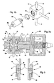
- FIG 1 is a schematic illustration of an embodiment of the present invention.
- FIG 2a is a cross-sectional view of block valve 14 of FIG 1.
- FIG 2b is an exploded perspective view of the block valve of FIG 2a.
- FIG 3 is a cross-sectional view of the low dead space connection 24 of FIG 1.
- the present invention provides a readily cleanable and purgeable manifold for delivery of low vapor pressure, high purity chemical to a process vessel, which in turn dispenses the chemical to a process tool or reactor for consumption.
- the apparatus of the present invention is particularly suited for process chemicals used in the semiconductor industry.
- the apparatus of the present invention is applicable to low vapor pressure chemicals, such as tetrakis(dimethylamido)titanium, it is also applicable to chemicals which do not have a low vapor pressure, i.e., high vapor pressure chemicals, and thus can be used with a wide array of chemicals.
- low vapor pressure chemicals such as tetrakis(dimethylamido)titanium
- high vapor pressure chemicals i.e., high vapor pressure chemicals
- the manifold and chemical delivery system of the present invention may be used in various applications with various fluids, but has particular application for liquid chemicals that have at least a high purity.
- the liquid chemical may be selected from the group consisting of tetraethylorthosilicate (TEOS), borazine, aluminum trisec-butoxide, carbon tetrachloride, trichloroethanes, chloroform, trimethylphosphite, dichloroethylenes, trimethylborate, dichloromethane, titanium n-butoxide, diethylsilane, hexafluoroacetylacetonato-copper(1)trimethylvinylsilane, isopropoxide, triethylphoshate, silicon tetrachloride, tantalum ethoxide, tetrakis(diethylamido)titanium (TDEAT), tetrakis(dimethylamido)titanium (TDMAT), bis-ter
- TDMAT as the low vapor pressure, high purity chemical delivered from a bulk source of such TDMAT (source of high purity chemical refill) to the process vessel and then to a process tool of a semiconductor fab, wherein the TDMAT is supplied to the process vessel from the bulk source container as a liquid by pressurized gas delivery and then to the process tool as a vapor where the process vessel acts as a "bubbler".
- the liquid chemical is entrained in a pressurized gas or carrier gas that is bubbled into the liquid chemical, as it resides in the process vessel, through a diptube which introduces the pressurized gas into the liquid chemical below the surface of the chemical.
- the pressurized gas entrains or vaporizes some of the chemical and the vapor leaves with the pressurized gas through an outlet communicating with the process tool.
- Pressurizing gas can be any inert gas, such as nitrogen, helium or the rare gases.
- a high purity chemical delivery system is illustrated wherein a bulk source of TDMAT 10, i.e., source of high purity chemical refill, provides low vapor pressure, high purity chemical in liquid form through second conduit 12 by means of pressurized gas administered to the head space of the source 10.
- the TDMAT is delivered to the diaphragm side of a first diaphragm valve in a block valve assembly 14.
- the TDMAT is then passed through a conduit 16 of a manifold which connects to a process vessel 28 through first low dead space connection 24 and a manual valve 26.
- Conduit 16 can have a second low dead space connection 22 for further disassembly of the manifold.
- Conduit 16 is preferably heated using heat tracing or other heater elements, electric or heated fluids, 15 and appropriate insulation to maintain conduit 16 at a temperature to volatilize the low vapor pressure, high purity chemical.
- the block valve assembly 14 preferably also has a heating element or tracing 17 similar to what is described for conduit 16.
- Conduit 12 is equipped with connector 19.
- the process vessel 28 is also outfitted with a source 30 of pressurized gas, such as nitrogen, that is connected through yet another, potentially low dead space, connection 32, manual valve 38 and diptube 50.
- the diptube 50 bubbles nitrogen through the chemical in vessel 28 to entrain or vaporize the chemical into the gas for delivery out of manual valve 40, potentially low dead space, connection 36, conduit 34 and valve 46 to the process tool destination 48, such as a titanium deposition reactor for a semiconductor integrated circuit product.
- Conduit 34 can be cleaned by venting through valve 42 to scrubber 44 by application of vacuum at the scrubber 44 and purge gas through conduit 30 in a repeated, cyclic manner until the conduit 34 is clean.
- This conduit 34 is not difficult to clean because it largely sees only vapor TDMAT and not liquid TDMAT (or other low vapor pressure, high purity chemical), in contrast to first conduit 16, which sees liquid chemical, such as TDMAT.
- First conduit 16 is cleaned by sequenced, repeated application of pressurized gas, such as nitrogen, and vacuum to first conduit 16 through the first block valve assembly 14, third conduit 18, second block valve assembly 20, potentially low dead space connection 52, pressurized gas conduit 54, check valve 56 and nitrogen pressurized gas source 58.
- Vacuum is supplied through second block valve assembly 20, potentially low dead space connection 60, vacuum line 62 and vacuum pump source 66. Vacuum can be monitored by vacuum gauge 64 through connector 65.
- FIG 2a shows greater detail of first block valve assembly 14, which is the same valve structure as second block valve assembly 20 (which is not shown separately in detail for that reason).
- FIG 2a is a partial cross-section of first block valve assembly 14 showing liquid low vapor pressure, high purity chemical or second conduit 12 in flow communication with first diaphragm valve 75 comprising diaphragm 74a comprising a flexible metal disk with a convex side and a concave side comprising the valve seat side of the valve and valve seat 78a, as well as an actuator similar to that shown for valve 77.
- Conduit 12 communicates with valve 75 through aperture 12a.
- the diaphragm side of the diaphragm comprises the cross-sectional triangular area between the concave surface of the diaphragm 74a, the floor of core 88 and the surface of valve seat 78a in the closed condition.
- Valve seat 78a engages the concave side of the diaphragm 74a and allows liquid low vapor pressure, high purity TDMAT to pass through the valve when the diaphragm disengages the valve seat 78a, to the short channel 76 to conduit 16 which connects with the process vessel 28.
- Diaphragm 74a is actuated by any means, such as manual actuator, electric solenoid, hydraulic pressure actuation or preferably as illustrated, a pneumatic actuator, illustrated for the other diaphragm valve of block valve assembly 14.
- Pressurizing gas and vacuum are provided to first conduit 16 by way of conduit 18 and a second diaphragm valve 77 comprising diaphragm 74, valve seat 78, actuator connector 70, actuator armature 80, pneumatic actuator 68, bias spring 82, bellows or piston 84, which translates pneumatic pressure to valve actuation through armature 80 and pneumatic source 86.
- Pneumatic gas is supplied to bellows 84 by source 86 and a coaxial channel in armature 80 which communicates with bellows 84 through aperture 83.
- Pneumatic actuator is engaged to the diaphragm by locking nut 72.
- Second diaphragm valve 77 has a diaphragm side of its diaphragm 74 and a valve seat side, just as diaphragm valve 75.
- Valve 75 has a similar actuator structure as illustrated for valve 77.
- valve seat side of the diaphragm valves of the present invention have very little dead space or volume where a low vapor pressure liquid chemical can be retained.
- diaphragm valves 75 and 77 are juxtaposed to one another at their valve seat sides and connect to the conduit 16 via the very short channel 76 bored out of the monoblock of the block valve assembly 14 base. Due to this advantageous arrangement of these two valves, it is possible to clean first conduit 16 by application of sequenced pressurizing gas and vacuum, without the need for additional means, such as solvents.
- Cleanout can be accomplished in a short interval, such as several hours of sequenced pressurized gas and vacuum, in contrast to prior art systems which take several days to reach the prescribed level of residual chemical in the conduits prior to detachment of the conduits for maintenance or changeout of the vessel 28.
- the valve seat side of the diaphragm valves comprises that portion of the valve in direct communication with the common conduit, such as 16, by way of the short channel, such as 76, and up to the sealing surface of the valve seat with the concave surface of the diaphragm when the valve is closed.
- the diaphragm side of the diaphragm valves comprises the other side of the sealing surface of the valve seat in communication with the aperture, such as 12a, and still under the concave side of the diaphragm.
- the diaphragm side of the diaphragm valve can be seen to constitute an annular, generally V-shaped cross-sectional space, as well as potentially areas on the convex side of the diaphragm, all of which can potentially become wetted with chemical and constitute a difficult area to effectively and quickly clean of such chemical. Therefore, the present invention, by having the common conduit or first conduit 16 communicate directly with the valve seat side of the diaphragm valves of the first block valve assembly and by having the diaphragm valves juxtaposed to one another through a very short connection or channel 76, affords a low dead space valve arrangement, which can be readily cleaned by application of sequenced, repeated pressurized gas and vacuum, without the use of solvent or use of extended purging.
- the pneumatic actuator 68 has a source 86 of pressurized air for valve actuation.
- the valve 77 is a normally closed valve which is biased to the closed position by spring 82 operating on baffle 84 and actuator armature 80 which pushes against diaphragm 77 to engage the valve seat 78.
- Pressurized air passes through a coaxial tube through the center of spring 82 to an aperture 83 in the actuator armature 80, which is on the opposite side of baffle 84 from the spring 82.
- the air pressure acts against the baffle and spring to bias the diaphragm 77 open via the armature 80 and allow chemical to flow through the valve.
- Valve 75 is similarly equipped with valve actuation equipment, not illustrated, similar to 68, 70, 72 and 86.
- FIG 2b shows an exploded perspective view of the block valve assembly of FIG 2a, this time showing the pneumatic actuator 68a for valve 75.
- the diaphragm valves locations illustrated for one valve as core 88, are bored out of a single monoblock of material, such as ceramics, plastics such as Teflon, or other suitable materials, but preferably is metal, such as electropolished stainless steel.
- Aperture 12a of second conduit 12 is illustrated to show the diaphragm side connection of the conduits in the valve.
- Valve seat 78a delineates the valve seat side of the sealing surface of the valve seat 78a and the diaphragm 74a, shown removed from its core location 88.
- Pneumatic actuator 68a is shown with its pneumatic gas source connection 86a.
- Chemical source or second conduit 12, pressurizing gas/vacuum source, or third conduit 18 and common or first conduit 16 to the process vessel 28 are shown respectively emanating from the monoblock of block valve assembly 14.
- Second block valve assembly 20 is similar to first block valve assembly 14 as illustrated in FIG 2a, with conduit 18 in this instance with regard to second block valve assembly 20 corresponding to the structure shown for first conduit 16, conduit 54 corresponding to the structure shown for second conduit 12, and conduit 62 corresponding to the structure shown for third conduit 18, as it relates to first block valve assembly.
- First low dead space connection 24 is illustrated in FIG 3.
- Sealing surface 90 of first conduit 16 ends with an annular knife edge 94 depending axially from the sealing surface in the direction of the sealing surface 89 of the conduit comprising the inlet of valve 26, which also has an annular knife edge 96 depending axially from its sealing surface.
- These knife edges 94 and 96 engage an annular sealing gasket 92, which is preferably a relatively soft metal to form a low dead space connection with a superior seal.
- Compression fitting 100 threadably engages ring 98 to force the respective knife edges into sealing engagement with the annular soft metal gasket 92.
- vessel 28 contains chemical, such as TDMAT. It is dispensed by pressurized gas, such as nitrogen, from conduit 30, bubbling through the liquid chemical in vessel 28. The TDMAT is entrained in the gas, which leaves the vessel through conduit 34 to process tool 48, where it is consumed.
- pressurized gas such as nitrogen
- Conduit 12 can have a connector 19 in accordance with FIG 3.
- diaphragm valve 75 is closed, diaphragm valve 77 is opened and the inside of conduit 16 is subject to repeated, sequential exposure to pressurized purge gas and vacuum from the cycling of second block valve assembly 20, to connect alternately gas through conduit 54 and vacuum through conduit 62 by the opening and closing of the two diaphragm valves of block valve assembly 20. Because there is very little dead space on the valve seat side of the diaphragm valves and the channel 76 between the juxtaposed diaphragm valves is very short due to its machining from a single monoblock of material, the conduit 16 is cleaned to the required extent in a matter of hours, rather than the days or solvent purging required prior to the present invention.
- first block valve assembly 14, conduit 16, heaters 15 and 17 and connectors 22 and 24 have been described with regard to refillable vessel 28, it is contemplated that a block valve assembly, heaters and connectors could be placed in conduit 12 to allow vessel 10 to be equipped in a similar manner to vessel 28, and therefore allow the conduit 12 to be quickly purged and cleaned without solvents or lengthy purge times when handling low vapor pressure, high purity chemicals.
Landscapes
- Engineering & Computer Science (AREA)
- Mechanical Engineering (AREA)
- General Engineering & Computer Science (AREA)
- Chemical Vapour Deposition (AREA)
- Feeding, Discharge, Calcimining, Fusing, And Gas-Generation Devices (AREA)
Abstract
Description
- Not applicable.
- Not applicable.
- The present invention relates to chemical delivery systems, and in particular to an apparatus for delivering high-purity or ultra-high purity chemicals to a use point, such as a semiconductor fabrication facility or tool(s) for chemical vapor deposition. Although the invention may have other applications, it is particularly applicable in semiconductor fabrication.
- Semiconductor manufacturers require chemicals having at least a high-purity for production processes to avoid defects in the fabrication of semiconductor devices. The chemicals used in the fabrication of integrated circuits usually must have an ultra-high purity to allow satisfactory process yields. As integrated circuits have decreased in size, there has been an increase in the need to maintain the purity of source chemicals.
- One ultra-high purity chemical used in the fabrication of integrated circuits is tetrakis(dimethylamido)titanium (TDMAT). TDMAT is used widely in integrated circuit manufacturing operations such as chemical vapor deposition (CVD) to form titanium and titanium nitride films, vias and barrier layers.
- Integrated circuit fabricators typically require TDMAT with 99.99+% purity, preferably 99.999999+%(8-9's+%) purity. This high degree of purity is necessary to maintain satisfactory process yields. It also necessitates the use of special equipment to contain and deliver the high-purity or ultra-high purity TDMAT to CVD reaction chambers.
- High-purity chemicals and ultra-high purity chemicals, such as TDMAT, are delivered from a bulk chemical delivery system to a use point, such as a semiconductor fabrication facility or tool(s). A delivery system for high-purity chemicals is disclosed in U.S. Pat. No. 5,465,766 (Seigele, et al.). (Related patents include U.S. Pat. Nos. 5,562,132; 5,590,695; 5,607,002; 5,711,354; 5,878,793 and 5,964,254.) The system comprises: a bulk canister located in a remote chemical cabinet with a delivery manifold/purge panel; a refillable stainless steel ampoule to supply high-purity source chemicals to an end user; and a control unit to supervise and control the refill operation and to monitor the level of the bulk container. The system has two basic modes of operation: (1) a normal process operation during which high-purity source chemical is supplied to the end user; and (2) the refill mode of operation during which the refillable stainless steel ampoule is refilled with high-purity chemical.
- Solvent purging systems for removal of low vapor pressure chemicals from process conduits are disclosed in US5,964,230 and US6,138,691. Such systems add additional complexity to purging and increase the amount of materials which must be disposed of.
- Low dead space couplings are known, such as US6,161,875.
- TDMAT is considered a low vapor pressure, high purity chemical by the semiconductor industry, and thus presents special problems when breaking a process line or changing out a process container where the line must be cleaned prior to such detachment. Significant time delays in cleaning down a line or conduit are a disadvantage in the throughput of a wafer processing facility, where expensive tools and large batch processing of expensive wafers, each containing hundreds of integrated circuits require fast processing and avoidance of significant or lengthy offline time for cleaning or changeout of process containers or vessels.
- The Present Invention is more specifically directed to the field of process chemical delivery in the electronics industry and other applications requiring low vapor pressure, high purity chemical delivery. More specifically, the present invention is directed to apparatus and processes for the cleaning of process chemical delivery lines, containers and associated apparatus, particularly during changeout of process chemical or process chemical containers in such process chemical delivery lines, quickly and thoroughly, but without the added complexity of solvent purge systems, when processing with low vapor pressure, high purity chemicals.
- Evacuation and gas purge of process chemical lines has been used to remove residual chemicals from delivery lines. Both vacuum draw and inert gas purge are successful in quickly removing high volatility chemicals, but are not effective with low volatility chemicals. Safety is a problem when extracting highly toxic materials.
- Use of solvents to remove residual chemicals has been suggested to remove low vapor pressure chemicals from process lines when the lines need to be disconnected such as for replacement of a vessel or container for either refill or maintenance. However, solvent systems are complex and require a source of solvent and a means to handle the contaminated solvent after it has been used for its cleaning function.
- The present invention overcomes the drawbacks of the prior art in purging and cleaning chemical process lines for low vapor pressure chemicals without the requirements of lengthy purge cycles of pressurized gas and vacuum or the complexity of solvent systems, as will be more fully set forth below.
- The present invention is a purgeable manifold for transfer of low vapor pressure high purity chemicals in a high purity chemical delivery system, comprising; (a) a first conduit for detachably connecting a first vessel for containing the high purity chemical to a second vessel of high purity chemical, a source of pressurized gas and a source of vacuum; (b) a first block valve assembly having first and second diaphragm valves, each diaphragm valve having a diaphragm and having a valve seat side and a diaphragm side, wherein the valve seat side of each diaphragm valve is juxtaposed to the other valve seat side of the other diaphragm valve, and each valve seat side of each diaphragm valve having high purity chemical flow communication with the first conduit; (c) a first low dead space connector in the first conduit for detaching the conduit from the first vessel; (d) a second conduit, for delivering low vapor pressure, high purity chemicals to the first vessel, the second conduit connected to the diaphragm side of the first diaphragm valve; and (e) a third conduit, for communicating in a sequenced manner, pressurized gas and vacuum to the first conduit, connected to the diaphragm side of the second diaphragm valve.
- More preferably, the present invention is a high purity chemical delivery system for refilling a vessel for low vapor pressure, high purity chemical and delivering the chemical to a process tool that uses the chemical, comprising: (a) a vessel for containing a low vapor pressure, high purity chemical; (b) a purgeable manifold for transfer of low vapor pressure high purity chemicals from a source of high purity chemical refill to the vessel, the manifold comprising; (i) a heated first conduit for detachably connecting the vessel to the source of high purity chemical refill, a source of pressurized gas and a source of vacuum; (ii) a heated first block valve assembly having first and second diaphragm valves, each diaphragm valve having a diaphragm and having a valve seat side and a diaphragm side, the diaphragm comprising a flexible disc having a convex side toward the diaphragm side of the valves and a concave side toward the valve seat side of the valve, wherein the valve seat side of each diaphragm valve is juxtaposed to the other valve seat side of the other diaphragm valve, and each valve seat side of each diaphragm valve having high purity chemical flow communication with the first conduit, each diaphragm valve has a pneumatic valve actuator operatively engaged to the convex side of the diaphragm to actuate an open and closed condition of the diaphragm valves; (iii) a first low dead space connector in the first conduit for detaching the conduit from the vessel; (iv) a second conduit, for delivering low vapor pressure, high purity chemicals to the vessel, the second conduit connected to the diaphragm side of the first diaphragm valve; (v) a third conduit, for communicating in a sequenced manner, pressurized gas and vacuum to the first conduit, connected to the diaphragm side of the second diaphragm valve; (c) a source of pressurized gas; (d) a source of vacuum and (e) a second block valve assembly having third and fourth diaphragm valves, each diaphragm valve having a diaphragm and having a valve seat side and a diaphragm side, wherein the valve seat side of each diaphragm valve is juxtaposed to the other valve seat side of the other diaphragm valve, each valve seat side of each diaphragm valve having flow communication with the third conduit, the third diaphragm valve connected to a source of pressurized gas through the diaphragm side of the third diaphragm valve, and the fourth diaphragm valve connected to a source of vacuum through the diaphragm side of the fourth diaphragm valve.
- FIG 1 is a schematic illustration of an embodiment of the present invention.
- FIG 2a is a cross-sectional view of
block valve 14 of FIG 1. - FIG 2b is an exploded perspective view of the block valve of FIG 2a.
- FIG 3 is a cross-sectional view of the low
dead space connection 24 of FIG 1. - The present invention provides a readily cleanable and purgeable manifold for delivery of low vapor pressure, high purity chemical to a process vessel, which in turn dispenses the chemical to a process tool or reactor for consumption. The apparatus of the present invention is particularly suited for process chemicals used in the semiconductor industry.
- Although the apparatus of the present invention is applicable to low vapor pressure chemicals, such as tetrakis(dimethylamido)titanium, it is also applicable to chemicals which do not have a low vapor pressure, i.e., high vapor pressure chemicals, and thus can be used with a wide array of chemicals.
- The manifold and chemical delivery system of the present invention may be used in various applications with various fluids, but has particular application for liquid chemicals that have at least a high purity. For example, the liquid chemical may be selected from the group consisting of tetraethylorthosilicate (TEOS), borazine, aluminum trisec-butoxide, carbon tetrachloride, trichloroethanes, chloroform, trimethylphosphite, dichloroethylenes, trimethylborate, dichloromethane, titanium n-butoxide, diethylsilane, hexafluoroacetylacetonato-copper(1)trimethylvinylsilane, isopropoxide, triethylphoshate, silicon tetrachloride, tantalum ethoxide, tetrakis(diethylamido)titanium (TDEAT), tetrakis(dimethylamido)titanium (TDMAT), bis-tertiarybutylamido silane, triethylborate, titanium tetrachloride, trimethylphosphate, trimethylorthosilicate, titanium ethoxide, tetramethyl-cyclo-tetrasiloxane, titanium n-propoxide, tris(trimethylsiloxy)boron, titanium isobutoxide, tris(trimethylsilyl)phosphate, 1,1,1,5,5,5-hexafluoro-2,4-pentanedione, tetramethylsilane and mixtures thereof.
- The solventless purgeable manifold for a chemical delivery system of the present invention will now be described with regard to a particular embodiment processing TDMAT as the low vapor pressure, high purity chemical delivered from a bulk source of such TDMAT (source of high purity chemical refill) to the process vessel and then to a process tool of a semiconductor fab, wherein the TDMAT is supplied to the process vessel from the bulk source container as a liquid by pressurized gas delivery and then to the process tool as a vapor where the process vessel acts as a "bubbler".
- In a bubbler, the liquid chemical is entrained in a pressurized gas or carrier gas that is bubbled into the liquid chemical, as it resides in the process vessel, through a diptube which introduces the pressurized gas into the liquid chemical below the surface of the chemical. The pressurized gas entrains or vaporizes some of the chemical and the vapor leaves with the pressurized gas through an outlet communicating with the process tool.
- It is also possible to use the present invention in a liquid delivery to the process tool where the process vessel delivers liquid chemical out a diptube to the process tool by the action of pressurization gas on the headspace or liquid surface of the chemical in the process vessel (direct liquid injection or DLI).
- Pressurizing gas can be any inert gas, such as nitrogen, helium or the rare gases.
- With reference to FIG 1, a high purity chemical delivery system is illustrated wherein a bulk source of TDMAT 10, i.e., source of high purity chemical refill, provides low vapor pressure, high purity chemical in liquid form through
second conduit 12 by means of pressurized gas administered to the head space of thesource 10. The TDMAT is delivered to the diaphragm side of a first diaphragm valve in ablock valve assembly 14. The TDMAT is then passed through aconduit 16 of a manifold which connects to aprocess vessel 28 through first lowdead space connection 24 and amanual valve 26.Conduit 16 can have a second lowdead space connection 22 for further disassembly of the manifold.Conduit 16 is preferably heated using heat tracing or other heater elements, electric or heated fluids, 15 and appropriate insulation to maintainconduit 16 at a temperature to volatilize the low vapor pressure, high purity chemical. Theblock valve assembly 14 preferably also has a heating element or tracing 17 similar to what is described forconduit 16. Conduit 12 is equipped withconnector 19. - The
process vessel 28 is also outfitted with asource 30 of pressurized gas, such as nitrogen, that is connected through yet another, potentially low dead space,connection 32,manual valve 38 anddiptube 50. Thediptube 50 bubbles nitrogen through the chemical invessel 28 to entrain or vaporize the chemical into the gas for delivery out ofmanual valve 40, potentially low dead space,connection 36,conduit 34 andvalve 46 to theprocess tool destination 48, such as a titanium deposition reactor for a semiconductor integrated circuit product.Conduit 34 can be cleaned by venting throughvalve 42 toscrubber 44 by application of vacuum at thescrubber 44 and purge gas throughconduit 30 in a repeated, cyclic manner until theconduit 34 is clean. Thisconduit 34 is not difficult to clean because it largely sees only vapor TDMAT and not liquid TDMAT (or other low vapor pressure, high purity chemical), in contrast tofirst conduit 16, which sees liquid chemical, such as TDMAT. -
First conduit 16 is cleaned by sequenced, repeated application of pressurized gas, such as nitrogen, and vacuum tofirst conduit 16 through the firstblock valve assembly 14,third conduit 18, second block valve assembly 20, potentially lowdead space connection 52,pressurized gas conduit 54,check valve 56 and nitrogen pressurizedgas source 58. Vacuum is supplied through second block valve assembly 20, potentially lowdead space connection 60,vacuum line 62 andvacuum pump source 66. Vacuum can be monitored byvacuum gauge 64 throughconnector 65. - FIG 2a shows greater detail of first
block valve assembly 14, which is the same valve structure as second block valve assembly 20 (which is not shown separately in detail for that reason). FIG 2a is a partial cross-section of firstblock valve assembly 14 showing liquid low vapor pressure, high purity chemical orsecond conduit 12 in flow communication withfirst diaphragm valve 75 comprisingdiaphragm 74a comprising a flexible metal disk with a convex side and a concave side comprising the valve seat side of the valve andvalve seat 78a, as well as an actuator similar to that shown forvalve 77.Conduit 12 communicates withvalve 75 throughaperture 12a. The diaphragm side of the diaphragm comprises the cross-sectional triangular area between the concave surface of thediaphragm 74a, the floor ofcore 88 and the surface ofvalve seat 78a in the closed condition.Valve seat 78a engages the concave side of thediaphragm 74a and allows liquid low vapor pressure, high purity TDMAT to pass through the valve when the diaphragm disengages thevalve seat 78a, to theshort channel 76 toconduit 16 which connects with theprocess vessel 28.Diaphragm 74a is actuated by any means, such as manual actuator, electric solenoid, hydraulic pressure actuation or preferably as illustrated, a pneumatic actuator, illustrated for the other diaphragm valve ofblock valve assembly 14. - Pressurizing gas and vacuum are provided to
first conduit 16 by way ofconduit 18 and asecond diaphragm valve 77 comprisingdiaphragm 74,valve seat 78,actuator connector 70,actuator armature 80,pneumatic actuator 68, bias spring 82, bellows orpiston 84, which translates pneumatic pressure to valve actuation througharmature 80 andpneumatic source 86. Pneumatic gas is supplied tobellows 84 bysource 86 and a coaxial channel inarmature 80 which communicates withbellows 84 throughaperture 83. Pneumatic actuator is engaged to the diaphragm by lockingnut 72.Second diaphragm valve 77 has a diaphragm side of itsdiaphragm 74 and a valve seat side, just asdiaphragm valve 75.Valve 75 has a similar actuator structure as illustrated forvalve 77. - The valve seat side of the diaphragm valves of the present invention have very little dead space or volume where a low vapor pressure liquid chemical can be retained. In addition,
diaphragm valves conduit 16 via the veryshort channel 76 bored out of the monoblock of theblock valve assembly 14 base. Due to this advantageous arrangement of these two valves, it is possible to cleanfirst conduit 16 by application of sequenced pressurizing gas and vacuum, without the need for additional means, such as solvents. Cleanout can be accomplished in a short interval, such as several hours of sequenced pressurized gas and vacuum, in contrast to prior art systems which take several days to reach the prescribed level of residual chemical in the conduits prior to detachment of the conduits for maintenance or changeout of thevessel 28. - The valve seat side of the diaphragm valves comprises that portion of the valve in direct communication with the common conduit, such as 16, by way of the short channel, such as 76, and up to the sealing surface of the valve seat with the concave surface of the diaphragm when the valve is closed. The diaphragm side of the diaphragm valves comprises the other side of the sealing surface of the valve seat in communication with the aperture, such as 12a, and still under the concave side of the diaphragm. The diaphragm side of the diaphragm valve can be seen to constitute an annular, generally V-shaped cross-sectional space, as well as potentially areas on the convex side of the diaphragm, all of which can potentially become wetted with chemical and constitute a difficult area to effectively and quickly clean of such chemical.
Therefore, the present invention, by having the common conduit orfirst conduit 16 communicate directly with the valve seat side of the diaphragm valves of the first block valve assembly and by having the diaphragm valves juxtaposed to one another through a very short connection orchannel 76, affords a low dead space valve arrangement, which can be readily cleaned by application of sequenced, repeated pressurized gas and vacuum, without the use of solvent or use of extended purging. - The
pneumatic actuator 68 has asource 86 of pressurized air for valve actuation. Thevalve 77 is a normally closed valve which is biased to the closed position by spring 82 operating onbaffle 84 andactuator armature 80 which pushes againstdiaphragm 77 to engage thevalve seat 78. Pressurized air passes through a coaxial tube through the center of spring 82 to anaperture 83 in theactuator armature 80, which is on the opposite side ofbaffle 84 from the spring 82. The air pressure acts against the baffle and spring to bias thediaphragm 77 open via thearmature 80 and allow chemical to flow through the valve. This represents only one of several ways a pneumatic actuator operates and the operation of the pneumatic actuator is not an aspect of the present invention. Any of the known methods and apparatus for actuating using pneumatics can be contemplated, and in fact non-pneumatic actuation can be used, such as manual or solenoid actuation.Valve 75 is similarly equipped with valve actuation equipment, not illustrated, similar to 68, 70, 72 and 86. - FIG 2b shows an exploded perspective view of the block valve assembly of FIG 2a, this time showing the
pneumatic actuator 68a forvalve 75. The diaphragm valves locations, illustrated for one valve ascore 88, are bored out of a single monoblock of material, such as ceramics, plastics such as Teflon, or other suitable materials, but preferably is metal, such as electropolished stainless steel.Aperture 12a ofsecond conduit 12 is illustrated to show the diaphragm side connection of the conduits in the valve.Valve seat 78a delineates the valve seat side of the sealing surface of thevalve seat 78a and thediaphragm 74a, shown removed from itscore location 88.Pneumatic actuator 68a is shown with its pneumaticgas source connection 86a. Chemical source orsecond conduit 12, pressurizing gas/vacuum source, orthird conduit 18 and common orfirst conduit 16 to theprocess vessel 28 are shown respectively emanating from the monoblock ofblock valve assembly 14. - Second block valve assembly 20 is similar to first
block valve assembly 14 as illustrated in FIG 2a, withconduit 18 in this instance with regard to second block valve assembly 20 corresponding to the structure shown forfirst conduit 16,conduit 54 corresponding to the structure shown forsecond conduit 12, andconduit 62 corresponding to the structure shown forthird conduit 18, as it relates to first block valve assembly. - First low
dead space connection 24 is illustrated in FIG 3. Sealingsurface 90 offirst conduit 16 ends with anannular knife edge 94 depending axially from the sealing surface in the direction of the sealingsurface 89 of the conduit comprising the inlet ofvalve 26, which also has anannular knife edge 96 depending axially from its sealing surface. These knife edges 94 and 96 engage anannular sealing gasket 92, which is preferably a relatively soft metal to form a low dead space connection with a superior seal. Compression fitting 100 threadably engagesring 98 to force the respective knife edges into sealing engagement with the annularsoft metal gasket 92. - In operation,
vessel 28 contains chemical, such as TDMAT. It is dispensed by pressurized gas, such as nitrogen, fromconduit 30, bubbling through the liquid chemical invessel 28. The TDMAT is entrained in the gas, which leaves the vessel throughconduit 34 to processtool 48, where it is consumed. - To refill
vessel 28, it is necessary for TDMAT from a bulk source of refill to be delivered intovessel 28 throughsecond conduit 12, firstblock valve assembly 14 andfirst conduit 16. At times, it is necessary to cleanfirst conduit 16 and firstblock valve assembly 14 periodically or for the purpose of maintenance, such as removal ofvessel 28. Beforefirst conduit 16 can be detached from thevessel 28, the first conduit must be very clean, or atmospheric reactions and corrosion can occur or operator exposure could occur with any residual chemical left in first conduit or the passageways associated withfirst conduit 16.Conduit 12 can have aconnector 19 in accordance with FIG 3. - For low vapor pressure chemicals, such as some of those listed above, i.e., TDMAT, such clean out of conduits conveying the liquid form of the chemical historically took days of purging and vacuum or required solvent purge. Using the apparatus of the present invention comprising a low dead space block valve assembly with diaphragm valves juxtaposed to one another in a single monoblock of material with the
first conduit 16 connected to the valve seat side of the diaphragm valves for bothchemical input 12 and gas/vacuum 18 assures that minimum space is required to be cleaned and minimal dead space exists where chemical could be retained. This significantly reduces the purge and vacuum times needed to effect appropriate levels of cleaning. - To clean
conduit 16,diaphragm valve 75 is closed,diaphragm valve 77 is opened and the inside ofconduit 16 is subject to repeated, sequential exposure to pressurized purge gas and vacuum from the cycling of second block valve assembly 20, to connect alternately gas throughconduit 54 and vacuum throughconduit 62 by the opening and closing of the two diaphragm valves of block valve assembly 20. Because there is very little dead space on the valve seat side of the diaphragm valves and thechannel 76 between the juxtaposed diaphragm valves is very short due to its machining from a single monoblock of material, theconduit 16 is cleaned to the required extent in a matter of hours, rather than the days or solvent purging required prior to the present invention. - Although the first
block valve assembly 14,conduit 16,heaters connectors refillable vessel 28, it is contemplated that a block valve assembly, heaters and connectors could be placed inconduit 12 to allowvessel 10 to be equipped in a similar manner tovessel 28, and therefore allow theconduit 12 to be quickly purged and cleaned without solvents or lengthy purge times when handling low vapor pressure, high purity chemicals. - The present invention has been set forth with regard to a preferred embodiment, but the full scope of the present invention should be ascertained from the claims below.
Claims (20)
- A purgeable manifold for transfer of low vapor pressure high purity chemicals in a high purity chemical delivery system, comprising:(a) a first conduit for detachably connecting a first vessel, for containing the high purity chemical, to a second vessel of high purity chemical, a source of pressurized gas and a source of vacuum;(b) a first block valve assembly having first and second diaphragm valves, each diaphragm valve having a diaphragm and having a valve seat side and a diaphragm side, wherein the valve seat side of each diaphragm valve is juxtaposed to the other valve seat side of the other diaphragm valve, and each valve seat side of each diaphragm valve having high purity chemical flow communication with said first conduit;(c) a first low dead space connector in said first conduit for detaching said conduit from said first vessel;(d) a second conduit, for delivering low vapor pressure, high purity chemicals to said first vessel from said source of high purity chemical refill, said second conduit connected to the diaphragm side of said first diaphragm valve; and(e) a third conduit, for communicating in a sequenced manner, pressurized gas and vacuum to said first conduit, connected to the diaphragm side of said second diaphragm valve.
- The manifold of Claim 1 wherein said diaphragms comprise a flexible disc having a convex side toward the diaphragm side of said valves and a concave side toward the valve seat side of said valve.
- The manifold of Claim 2 wherein each diaphragm valve has a valve actuator operatively engaged to the convex side of said diaphragm to actuate an open and closed condition of said diaphragm valves.
- The manifold of Claim1 further comprising a heater for said first conduit and said first block valve assembly.
- The manifold of Claim 1 having a second block valve assembly having third and fourth diaphragm valves, each diaphragm valve having a diaphragm and having a valve seat side and a diaphragm side, wherein the valve seat side of each diaphragm valve is juxtaposed to the other valve seat side of the other diaphragm valve, each valve seat side of each diaphragm valve having flow communication with said third conduit, said third diaphragm valve connected to a source of pressurized gas through the diaphragm side of said third diaphragm valve, and said fourth diaphragm valve connected to a source of vacuum through the diaphragm side of said fourth diaphragm valve.
- The manifold of Claim 5 wherein each diaphragm valve has a valve actuator operatively engaged to the convex side of said diaphragm to actuate an open and closed condition of said diaphragm valves.
- The manifold of Claim 1 wherein said first low dead space connector comprises a first sealing surface on said first conduit, a second sealing surface on a conduit connected to said first vessel, an annular sealing gasket between said first and second sealing surfaces, wherein said first and second sealing surfaces have a knife edge depending axially from each surface engaging and deforming said annular sealing gasket, and a compression fitting for forceably engaging said first and second sealing surfaces and said annular sealing gasket.
- A purgeable manifold for transfer of low vapor pressure high purity chemicals in a high purity chemical delivery system, comprising:(a) a first conduit for detachably connecting a vessel for dispensing the high purity chemical to a source of high purity chemical refill, a source of pressurized gas and a source of vacuum;(b) a first block valve assembly having first and second diaphragm valves, each diaphragm valve having a diaphragm and having a valve seat side and a diaphragm side, said diaphragm comprising a flexible disc having a convex side toward the diaphragm side of said valves and a concave side toward the valve seat side of said valve, wherein the valve seat side of each diaphragm valve is juxtaposed to the other valve seat side of the other diaphragm valve, and each valve seat side of each diaphragm valve having high purity chemical flow communication with said first conduit, each diaphragm valve has a pneumatic valve actuator operatively engaged to the convex side of said diaphragm to actuate an open and closed condition of said diaphragm valves;(c) a first low dead space connector in said first conduit for detaching said conduit from said vessel;(d) a second conduit, for delivering low vapor pressure, high purity chemicals to said vessel from said source of high purity chemical refill, said second conduit connected to the diaphragm side of said first diaphragm valve;(e) a third conduit, for communicating in a sequenced manner, pressurized gas and vacuum to said first conduit, connected to the diaphragm side of said second diaphragm valve; and(f) a second block valve assembly having third and fourth diaphragm valves, each diaphragm valve having a diaphragm and having a valve seat side and a diaphragm side, wherein the valve seat side of each diaphragm valve is juxtaposed to the other valve seat side of the other diaphragm valve, each valve seat side of each diaphragm valve having flow communication with said third conduit, said third diaphragm valve connected to a source of pressurized gas through the diaphragm side of said third diaphragm valve, and said fourth diaphragm valve connected to a source of vacuum through the diaphragm side of said fourth diaphragm valve.
- The manifold of Claim 8 wherein said first conduit is connected to said vessel through a second low dead space connector and a fifth valve connected to said vessel.
- The manifold of Claim 9 wherein said vessel has an outlet to dispense said low vapor pressure, high purity chemical to a process tool that uses said chemical.
- The manifold of Claim 10 wherein said outlet has a valve to control the flow of said low vapor pressure, high purity chemical.
- The manifold of Claim 10 wherein said vessel has a diptube inlet to supply a second source of pressurized gas to said vessel.
- The manifold of Claim 12 wherein said inlet has a valve to control the flow of said pressurized gas.
- A high purity chemical delivery system for refilling a vessel for low vapor pressure, high purity chemical and delivering said chemical to a process tool that uses said chemical, comprising:(a) a vessel for containing a low vapor pressure, high purity chemical;(b) a purgeable manifold for transfer of low vapor pressure high purity chemicals from a source of high purity chemical refill to said vessel, comprising; (i) a heated first conduit for detachably connecting said vessel to said source of high purity chemical refill, a source of pressurized gas and a source of vacuum; (ii) a heated first block valve assembly having first and second diaphragm valves, each diaphragm valve having a diaphragm and having a valve seat side and a diaphragm side, said diaphragm comprising a flexible disc having a convex side toward the diaphragm side of said valves and a concave side toward the valve seat side of said valve, wherein the valve seat side of each diaphragm valve is juxtaposed to the other valve seat side of the other diaphragm valve, and each valve seat side of each diaphragm valve having high purity chemical flow communication with said first conduit, each diaphragm valve has a pneumatic valve actuator operatively engaged to the convex side of said diaphragm to actuate an open and closed condition of said diaphragm valves; (iii) a first low dead space connector in said first conduit for detaching said conduit from said vessel; (iv) a second conduit, for delivering low vapor pressure, high purity chemicals to said vessel from said source of high purity chemical refill, said second conduit connected to the diaphragm side of said first diaphragm valve; (v) a third conduit, for communicating in a sequenced manner, pressurized gas and vacuum to said first conduit, connected to the diaphragm side of said second diaphragm valve;(c) a source of pressurized gas; and(d) a source of vacuum.
- A high purity chemical delivery system for refilling a vessel for low vapor pressure, high purity chemical and delivering said chemical to a process tool that uses said chemical, comprising:(a) a vessel for containing a low vapor pressure, high purity chemical;(b) a purgeable manifold for transfer of low vapor pressure high purity chemicals from a source of high purity chemical refill to said vessel, comprising; (i) a heated first conduit for detachably connecting said vessel to said source of high purity chemical refill, a source of pressurized gas and a source of vacuum; (ii) a heated first block valve assembly having first and second diaphragm valves, each diaphragm valve having a diaphragm and having a valve seat side and a diaphragm side, said diaphragm comprising a flexible disc having a convex side toward the diaphragm side of said valves and a concave side toward the valve seat side of said valve, wherein the valve seat side of each diaphragm valve is juxtaposed to the other valve seat side of the other diaphragm valve, and each valve seat side of each diaphragm valve having high purity chemical flow communication with said first conduit, each diaphragm valve has a pneumatic valve actuator operatively engaged to the convex side of said diaphragm to actuate an open and closed condition of said diaphragm valves; (iii) a first low dead space connector in said first conduit for detaching said conduit from said vessel; (iv) a second conduit, for delivering low vapor pressure, high purity chemicals to said vessel from said source of high purity chemical refill, said second conduit connected to the diaphragm side of said first diaphragm valve; (v) a third conduit, for communicating in a sequenced manner, pressurized gas and vacuum to said first conduit, connected to the diaphragm side of said second diaphragm valve;(c) a source of pressurized gas;(d) a source of vacuum;(e) a second block valve assembly having third and fourth diaphragm valves, each diaphragm valve having a diaphragm and having a valve seat side and a diaphragm side, wherein the valve seat side of each diaphragm valve is juxtaposed to the other valve seat side of the other diaphragm valve, each valve seat side of each diaphragm valve having flow communication with said third conduit, said third diaphragm valve connected to a source of pressurized gas through the diaphragm side of said third diaphragm valve, and said fourth diaphragm valve connected to a source of vacuum through the diaphragm side of said fourth diaphragm valve.
- The manifold of Claim 15 wherein said first conduit is connected to said vessel through a second low dead space connector and a fifth valve connected to said vessel.
- The manifold of Claim 15 wherein said vessel has an outlet to dispense said low vapor pressure, high purity chemical to a process tool that uses said chemical.
- The manifold of Claim 15 wherein said outlet has a valve to control the flow of said low vapor pressure, high purity chemical.
- The manifold of Claim 15 wherein said vessel has a diptube inlet to supply a second source of pressurized gas to said vessel.
- The manifold of Claim 19 wherein said inlet has a valve to control the flow of said pressurized gas.
Applications Claiming Priority (2)
| Application Number | Priority Date | Filing Date | Title |
|---|---|---|---|
| US938883 | 2001-08-24 | ||
| US09/938,883 US6431229B1 (en) | 2001-08-24 | 2001-08-24 | Solventless purgeable diaphragm valved manifold for low vapor pressure chemicals |
Publications (3)
| Publication Number | Publication Date |
|---|---|
| EP1288544A2 true EP1288544A2 (en) | 2003-03-05 |
| EP1288544A3 EP1288544A3 (en) | 2004-01-02 |
| EP1288544B1 EP1288544B1 (en) | 2010-06-02 |
Family
ID=25472135
Family Applications (1)
| Application Number | Title | Priority Date | Filing Date |
|---|---|---|---|
| EP02018166A Expired - Lifetime EP1288544B1 (en) | 2001-08-24 | 2002-08-19 | Diaphragm valved manifold for chemicals |
Country Status (4)
| Country | Link |
|---|---|
| US (1) | US6431229B1 (en) |
| EP (1) | EP1288544B1 (en) |
| AT (1) | ATE470096T1 (en) |
| DE (1) | DE60236564D1 (en) |
Cited By (1)
| Publication number | Priority date | Publication date | Assignee | Title |
|---|---|---|---|---|
| EP1365041A1 (en) | 2002-05-23 | 2003-11-26 | Air Products And Chemicals, Inc. | Purgeable manifold |
Families Citing this family (22)
| Publication number | Priority date | Publication date | Assignee | Title |
|---|---|---|---|---|
| US6837251B1 (en) * | 2000-06-21 | 2005-01-04 | Air Products And Chemicals, Inc. | Multiple contents container assembly for ultrapure solvent purging |
| US6953047B2 (en) * | 2002-01-14 | 2005-10-11 | Air Products And Chemicals, Inc. | Cabinet for chemical delivery with solvent purging |
| US6966348B2 (en) * | 2002-05-23 | 2005-11-22 | Air Products And Chemicals, Inc. | Purgeable container for low vapor pressure chemicals |
| JP3854555B2 (en) * | 2002-08-30 | 2006-12-06 | 東京エレクトロン株式会社 | Thin film forming apparatus and thin film forming method |
| US6880592B2 (en) * | 2003-06-26 | 2005-04-19 | Advanced Technology Materials, Inc. | Canister guard |
| US7290572B2 (en) * | 2005-07-10 | 2007-11-06 | David James Silva | Method for purging a high purity manifold |
| US7114531B2 (en) * | 2004-07-13 | 2006-10-03 | David James Silva | System and method for purging high purity interfaces |
| US20070017596A1 (en) * | 2004-07-13 | 2007-01-25 | Silva David J | System for purging high purity interfaces |
| US7198072B2 (en) * | 2004-07-13 | 2007-04-03 | David James Silva | Purgeable manifold system |
| US7114522B2 (en) * | 2004-09-18 | 2006-10-03 | David James Silva | Adapter manifold with dual valve block |
| US20060086398A1 (en) * | 2004-10-27 | 2006-04-27 | Silva David J | Three valve block assembly |
| US7198056B2 (en) * | 2005-02-10 | 2007-04-03 | David James Silva | High purity chemical delivery system |
| US20070175392A1 (en) * | 2006-01-27 | 2007-08-02 | American Air Liquide, Inc. | Multiple precursor dispensing apparatus |
| DE102007011589A1 (en) * | 2007-03-08 | 2008-09-11 | Schott Ag | Conveyor for precursor |
| EP2517797B1 (en) * | 2007-03-24 | 2020-05-27 | Afa Polytek B.V. | Precompression system for a liquid dispensing device and method of assembling such precompression system |
| US8002247B2 (en) * | 2008-08-22 | 2011-08-23 | Air Products And Chemicals, Inc. | Cross purge valve and container assembly |
| EP2715781B1 (en) * | 2011-05-28 | 2020-07-01 | Entegris Inc. | Refillable ampoule with purge capability |
| US9598766B2 (en) | 2012-05-27 | 2017-03-21 | Air Products And Chemicals, Inc. | Vessel with filter |
| US20150153003A1 (en) * | 2013-09-17 | 2015-06-04 | J. W. Randolph Miller | Nitric oxide cylinder filling apparatus and method |
| JP2016134569A (en) * | 2015-01-21 | 2016-07-25 | 株式会社東芝 | Semiconductor manufacturing equipment |
| EP3912688A1 (en) * | 2020-05-19 | 2021-11-24 | L'air Liquide, Société Anonyme Pour L'Étude Et L'exploitation Des Procédés Georges Claude | Secure inerting device |
| KR20230040279A (en) * | 2021-09-15 | 2023-03-22 | 에이에스엠 아이피 홀딩 비.브이. | Method and apparatus for controlling a liquid |
Citations (1)
| Publication number | Priority date | Publication date | Assignee | Title |
|---|---|---|---|---|
| US5549134A (en) | 1994-05-27 | 1996-08-27 | Marcvalve Corporation | Diaphragm valve |
Family Cites Families (14)
| Publication number | Priority date | Publication date | Assignee | Title |
|---|---|---|---|---|
| BE510748A (en) * | ||||
| US4181154A (en) * | 1978-02-27 | 1980-01-01 | Ara Services, Inc. | Deflector valve for fluids |
| US4715578A (en) * | 1986-12-22 | 1987-12-29 | Cla-Val Company | Diaphragm valve |
| US5252134A (en) * | 1991-05-31 | 1993-10-12 | Stauffer Craig M | Integrated delivery system for chemical vapor from non-gaseous sources for semiconductor processing |
| DE4132541A1 (en) * | 1991-09-30 | 1993-04-01 | Herion Werke Kg | VALVE BLOCK |
| EP0619450A1 (en) * | 1993-04-09 | 1994-10-12 | The Boc Group, Inc. | Zero Dead-Leg Gas Cabinet |
| US5607002A (en) | 1993-04-28 | 1997-03-04 | Advanced Delivery & Chemical Systems, Inc. | Chemical refill system for high purity chemicals |
| US5465766A (en) | 1993-04-28 | 1995-11-14 | Advanced Delivery & Chemical Systems, Inc. | Chemical refill system for high purity chemicals |
| US5878793A (en) | 1993-04-28 | 1999-03-09 | Siegele; Stephen H. | Refillable ampule and method re same |
| US5964254A (en) | 1997-07-11 | 1999-10-12 | Advanced Delivery & Chemical Systems, Ltd. | Delivery system and manifold |
| JP3280119B2 (en) * | 1993-06-02 | 2002-04-30 | 清原 まさ子 | Diaphragm valve |
| WO1998027247A1 (en) | 1996-12-17 | 1998-06-25 | Advanced Technology Materials, Inc. | Reagent supply vessel for chemical vapor deposition |
| US5964230A (en) | 1997-10-06 | 1999-10-12 | Air Products And Chemicals, Inc. | Solvent purge mechanism |
| JP3965512B2 (en) | 1998-03-31 | 2007-08-29 | 株式会社フジキン | Gasket retainer used in fluid coupling and fluid coupling |
-
2001
- 2001-08-24 US US09/938,883 patent/US6431229B1/en not_active Expired - Lifetime
-
2002
- 2002-08-19 AT AT02018166T patent/ATE470096T1/en not_active IP Right Cessation
- 2002-08-19 DE DE60236564T patent/DE60236564D1/en not_active Expired - Lifetime
- 2002-08-19 EP EP02018166A patent/EP1288544B1/en not_active Expired - Lifetime
Patent Citations (1)
| Publication number | Priority date | Publication date | Assignee | Title |
|---|---|---|---|---|
| US5549134A (en) | 1994-05-27 | 1996-08-27 | Marcvalve Corporation | Diaphragm valve |
Cited By (2)
| Publication number | Priority date | Publication date | Assignee | Title |
|---|---|---|---|---|
| EP1365041A1 (en) | 2002-05-23 | 2003-11-26 | Air Products And Chemicals, Inc. | Purgeable manifold |
| EP1365041B1 (en) * | 2002-05-23 | 2013-10-30 | Air Products And Chemicals, Inc. | Purgeable manifold |
Also Published As
| Publication number | Publication date |
|---|---|
| ATE470096T1 (en) | 2010-06-15 |
| EP1288544A3 (en) | 2004-01-02 |
| US6431229B1 (en) | 2002-08-13 |
| DE60236564D1 (en) | 2010-07-15 |
| EP1288544B1 (en) | 2010-06-02 |
Similar Documents
| Publication | Publication Date | Title |
|---|---|---|
| US6431229B1 (en) | Solventless purgeable diaphragm valved manifold for low vapor pressure chemicals | |
| US7487806B2 (en) | Source liquid supply apparatus having a cleaning function | |
| US7334595B2 (en) | Cabinet for chemical delivery with solvent purging and removal | |
| EP1519101B1 (en) | Purgeable container | |
| EP1365041B1 (en) | Purgeable manifold | |
| US6296026B1 (en) | Chemical delivery system having purge system utilizing multiple purge techniques | |
| EP2157341B1 (en) | Cross purge valve and container assembly | |
| US5964230A (en) | Solvent purge mechanism | |
| US20090214779A1 (en) | Multiple ampoule delivery systems | |
| US6199599B1 (en) | Chemical delivery system having purge system utilizing multiple purge techniques | |
| US6296025B1 (en) | Chemical delivery system having purge system utilizing multiple purge techniques | |
| WO1999064780A9 (en) | Chemical delivery system having purge system utilizing multiple purge techniques |
Legal Events
| Date | Code | Title | Description |
|---|---|---|---|
| PUAI | Public reference made under article 153(3) epc to a published international application that has entered the european phase |
Free format text: ORIGINAL CODE: 0009012 |
|
| AK | Designated contracting states |
Kind code of ref document: A2 Designated state(s): AT BE BG CH CY CZ DE DK EE ES FI FR GB GR IE IT LI LU MC NL PT SE SK TR Designated state(s): AT BE BG CH CY CZ DE DK EE ES FI FR GB GR IE IT LI LU MC NL PT SE SK TR |
|
| AX | Request for extension of the european patent |
Extension state: AL LT LV MK RO SI |
|
| PUAL | Search report despatched |
Free format text: ORIGINAL CODE: 0009013 |
|
| AK | Designated contracting states |
Kind code of ref document: A3 Designated state(s): AT BE BG CH CY CZ DE DK EE ES FI FR GB GR IE IT LI LU MC NL PT SE SK TR |
|
| AX | Request for extension of the european patent |
Extension state: AL LT LV MK RO SI |
|
| 17P | Request for examination filed |
Effective date: 20040219 |
|
| 17Q | First examination report despatched |
Effective date: 20040420 |
|
| AKX | Designation fees paid |
Designated state(s): AT BE BG CH CY CZ DE DK EE ES FI FR GB GR IE IT LI LU MC NL PT SE SK TR |
|
| 17Q | First examination report despatched |
Effective date: 20040420 |
|
| GRAP | Despatch of communication of intention to grant a patent |
Free format text: ORIGINAL CODE: EPIDOSNIGR1 |
|
| GRAS | Grant fee paid |
Free format text: ORIGINAL CODE: EPIDOSNIGR3 |
|
| GRAA | (expected) grant |
Free format text: ORIGINAL CODE: 0009210 |
|
| AK | Designated contracting states |
Kind code of ref document: B1 Designated state(s): AT BE BG CH CY CZ DE DK EE ES FI FR GB GR IE IT LI LU MC NL PT SE SK TR |
|
| REG | Reference to a national code |
Ref country code: GB Ref legal event code: FG4D |
|
| REG | Reference to a national code |
Ref country code: CH Ref legal event code: EP |
|
| REG | Reference to a national code |
Ref country code: IE Ref legal event code: FG4D |
|
| REF | Corresponds to: |
Ref document number: 60236564 Country of ref document: DE Date of ref document: 20100715 Kind code of ref document: P |
|
| REG | Reference to a national code |
Ref country code: NL Ref legal event code: T3 |
|
| PG25 | Lapsed in a contracting state [announced via postgrant information from national office to epo] |
Ref country code: SE Free format text: LAPSE BECAUSE OF FAILURE TO SUBMIT A TRANSLATION OF THE DESCRIPTION OR TO PAY THE FEE WITHIN THE PRESCRIBED TIME-LIMIT Effective date: 20100602 |
|
| PG25 | Lapsed in a contracting state [announced via postgrant information from national office to epo] |
Ref country code: FI Free format text: LAPSE BECAUSE OF FAILURE TO SUBMIT A TRANSLATION OF THE DESCRIPTION OR TO PAY THE FEE WITHIN THE PRESCRIBED TIME-LIMIT Effective date: 20100602 Ref country code: AT Free format text: LAPSE BECAUSE OF FAILURE TO SUBMIT A TRANSLATION OF THE DESCRIPTION OR TO PAY THE FEE WITHIN THE PRESCRIBED TIME-LIMIT Effective date: 20100602 |
|
| PG25 | Lapsed in a contracting state [announced via postgrant information from national office to epo] |
Ref country code: GR Free format text: LAPSE BECAUSE OF FAILURE TO SUBMIT A TRANSLATION OF THE DESCRIPTION OR TO PAY THE FEE WITHIN THE PRESCRIBED TIME-LIMIT Effective date: 20100903 Ref country code: CY Free format text: LAPSE BECAUSE OF FAILURE TO SUBMIT A TRANSLATION OF THE DESCRIPTION OR TO PAY THE FEE WITHIN THE PRESCRIBED TIME-LIMIT Effective date: 20100602 |
|
| PG25 | Lapsed in a contracting state [announced via postgrant information from national office to epo] |
Ref country code: EE Free format text: LAPSE BECAUSE OF FAILURE TO SUBMIT A TRANSLATION OF THE DESCRIPTION OR TO PAY THE FEE WITHIN THE PRESCRIBED TIME-LIMIT Effective date: 20100602 |
|
| PG25 | Lapsed in a contracting state [announced via postgrant information from national office to epo] |
Ref country code: CZ Free format text: LAPSE BECAUSE OF FAILURE TO SUBMIT A TRANSLATION OF THE DESCRIPTION OR TO PAY THE FEE WITHIN THE PRESCRIBED TIME-LIMIT Effective date: 20100602 Ref country code: PT Free format text: LAPSE BECAUSE OF FAILURE TO SUBMIT A TRANSLATION OF THE DESCRIPTION OR TO PAY THE FEE WITHIN THE PRESCRIBED TIME-LIMIT Effective date: 20101004 Ref country code: SK Free format text: LAPSE BECAUSE OF FAILURE TO SUBMIT A TRANSLATION OF THE DESCRIPTION OR TO PAY THE FEE WITHIN THE PRESCRIBED TIME-LIMIT Effective date: 20100602 Ref country code: BE Free format text: LAPSE BECAUSE OF FAILURE TO SUBMIT A TRANSLATION OF THE DESCRIPTION OR TO PAY THE FEE WITHIN THE PRESCRIBED TIME-LIMIT Effective date: 20100602 |
|
| PG25 | Lapsed in a contracting state [announced via postgrant information from national office to epo] |
Ref country code: MC Free format text: LAPSE BECAUSE OF NON-PAYMENT OF DUE FEES Effective date: 20100831 |
|
| REG | Reference to a national code |
Ref country code: CH Ref legal event code: PL |
|
| PLBE | No opposition filed within time limit |
Free format text: ORIGINAL CODE: 0009261 |
|
| STAA | Information on the status of an ep patent application or granted ep patent |
Free format text: STATUS: NO OPPOSITION FILED WITHIN TIME LIMIT |
|
| PG25 | Lapsed in a contracting state [announced via postgrant information from national office to epo] |
Ref country code: LI Free format text: LAPSE BECAUSE OF NON-PAYMENT OF DUE FEES Effective date: 20100831 Ref country code: CH Free format text: LAPSE BECAUSE OF NON-PAYMENT OF DUE FEES Effective date: 20100831 Ref country code: DK Free format text: LAPSE BECAUSE OF FAILURE TO SUBMIT A TRANSLATION OF THE DESCRIPTION OR TO PAY THE FEE WITHIN THE PRESCRIBED TIME-LIMIT Effective date: 20100602 |
|
| 26N | No opposition filed |
Effective date: 20110303 |
|
| REG | Reference to a national code |
Ref country code: DE Ref legal event code: R097 Ref document number: 60236564 Country of ref document: DE Effective date: 20110302 |
|
| PG25 | Lapsed in a contracting state [announced via postgrant information from national office to epo] |
Ref country code: BG Free format text: LAPSE BECAUSE OF FAILURE TO SUBMIT A TRANSLATION OF THE DESCRIPTION OR TO PAY THE FEE WITHIN THE PRESCRIBED TIME-LIMIT Effective date: 20100602 Ref country code: LU Free format text: LAPSE BECAUSE OF NON-PAYMENT OF DUE FEES Effective date: 20100819 |
|
| PG25 | Lapsed in a contracting state [announced via postgrant information from national office to epo] |
Ref country code: TR Free format text: LAPSE BECAUSE OF FAILURE TO SUBMIT A TRANSLATION OF THE DESCRIPTION OR TO PAY THE FEE WITHIN THE PRESCRIBED TIME-LIMIT Effective date: 20100602 |
|
| PG25 | Lapsed in a contracting state [announced via postgrant information from national office to epo] |
Ref country code: BG Free format text: LAPSE BECAUSE OF FAILURE TO SUBMIT A TRANSLATION OF THE DESCRIPTION OR TO PAY THE FEE WITHIN THE PRESCRIBED TIME-LIMIT Effective date: 20100902 |
|
| PG25 | Lapsed in a contracting state [announced via postgrant information from national office to epo] |
Ref country code: ES Free format text: LAPSE BECAUSE OF FAILURE TO SUBMIT A TRANSLATION OF THE DESCRIPTION OR TO PAY THE FEE WITHIN THE PRESCRIBED TIME-LIMIT Effective date: 20100913 |
|
| REG | Reference to a national code |
Ref country code: FR Ref legal event code: PLFP Year of fee payment: 14 |
|
| REG | Reference to a national code |
Ref country code: FR Ref legal event code: PLFP Year of fee payment: 15 |
|
| REG | Reference to a national code |
Ref country code: FR Ref legal event code: PLFP Year of fee payment: 16 |
|
| REG | Reference to a national code |
Ref country code: DE Ref legal event code: R082 Ref document number: 60236564 Country of ref document: DE Representative=s name: SSM SANDMAIR PATENTANWAELTE RECHTSANWALT PARTN, DE Ref country code: DE Ref legal event code: R082 Ref document number: 60236564 Country of ref document: DE Representative=s name: SCHWABE SANDMAIR MARX PATENTANWAELTE RECHTSANW, DE Ref country code: DE Ref legal event code: R081 Ref document number: 60236564 Country of ref document: DE Owner name: VERSUM MATERIALS US, LLC (N.D.GES. DES STAATES, US Free format text: FORMER OWNER: AIR PRODUCTS AND CHEMICALS, INC., ALLENTOWN, PA., US |
|
| REG | Reference to a national code |
Ref country code: GB Ref legal event code: 732E Free format text: REGISTERED BETWEEN 20171123 AND 20171129 |
|
| REG | Reference to a national code |
Ref country code: FR Ref legal event code: PLFP Year of fee payment: 17 |
|
| REG | Reference to a national code |
Ref country code: NL Ref legal event code: PD Owner name: VERSUM MATERIALS US, LLC; US Free format text: DETAILS ASSIGNMENT: CHANGE OF OWNER(S), ASSIGNMENT; FORMER OWNER NAME: AIR PRODUCTS AND CHEMICALS, INC. Effective date: 20181221 |
|
| PGFP | Annual fee paid to national office [announced via postgrant information from national office to epo] |
Ref country code: NL Payment date: 20210716 Year of fee payment: 20 |
|
| PGFP | Annual fee paid to national office [announced via postgrant information from national office to epo] |
Ref country code: IT Payment date: 20210712 Year of fee payment: 20 Ref country code: IE Payment date: 20210810 Year of fee payment: 20 Ref country code: FR Payment date: 20210715 Year of fee payment: 20 |
|
| PGFP | Annual fee paid to national office [announced via postgrant information from national office to epo] |
Ref country code: DE Payment date: 20210706 Year of fee payment: 20 Ref country code: GB Payment date: 20210714 Year of fee payment: 20 |
|
| REG | Reference to a national code |
Ref country code: DE Ref legal event code: R071 Ref document number: 60236564 Country of ref document: DE |
|
| REG | Reference to a national code |
Ref country code: NL Ref legal event code: MK Effective date: 20220818 |
|
| REG | Reference to a national code |
Ref country code: GB Ref legal event code: PE20 Expiry date: 20220818 |
|
| REG | Reference to a national code |
Ref country code: IE Ref legal event code: MK9A |
|
| PG25 | Lapsed in a contracting state [announced via postgrant information from national office to epo] |
Ref country code: IE Free format text: LAPSE BECAUSE OF EXPIRATION OF PROTECTION Effective date: 20220819 Ref country code: GB Free format text: LAPSE BECAUSE OF EXPIRATION OF PROTECTION Effective date: 20220818 |